IMPORTANT
Installer: Leave Instollotlon Instructions
with the homeowner
Save Installation Instructions for local electrlcal Inspector???s use
I
Part No.
30??? Freestanding
Gas Range
IMPORTANT
Installer: Leave Instollotlon Instructions
with the homeowner
Save Installation Instructions for local electrlcal Inspector???s use
I
Part No.
30??? Freestanding
Gas Range

bols needed for installbtion.
6 I rotlng plate are for elevations
UP 12 2.0X feat. 2M3 feet. rahngs at Q rate of 4% for
For elavahorn above sbuld bo reduced each I.033 feet
Gas Supply 3b3quirements,
05serve cllgoverningcodes
and ordinanceC

Electrical
Requirements
(II model is sa equipped.)
Eleclrical Shock Hazard
*Eleclricol gwund is requwd on this appliance.
*Do Not have o fuse in Ihe neutrot or groundlng 5rcuII. A fuse in the neulrol or grounding circuit could
resull in an electrical shock. Failure lo fo11su these inslruclions could resull in Ilre, electrical shock or olher persz~nal injury.
A tiring dia$an) k lrr&dedJtilit~r&x package. llw wiring diagram k also located on th+ bock of the range.
Recokmtitidkd
Grounding Methc d
Do NOT. UNDER ANY CIRCUMSTANCES.
REMOVE THE POWER SUPPLY CORD.
GROyJDlNG;FRONG.
Figure 1 ???I???
Temporary
Grounding Methc bd
DO NOT, UNDER ANY CIRCUMSTANCES,
REMOVE THE POWER SUPPLY CORD
GROUNDING ???RONG.
Now Start...
2, ???10ce one foot on the shipplng
. 30% IIt range forward slightly
t0 free rear legs Gentiy lower rO???Qe to floor. Tlt range bockwords until front legs are hee
;backguord do& until locked into place. Lift cooktop and
insert buckguard electrical
:connector plug Into
Check nMt wiring is not klnked or pinched bebeen holders and backguard.
*To Iprevent Ilpping, lnslall range
. Saw these Inslollol,on lnslruclions
If rtlnge IS moved 10 o new locol,on, the
renoved and re,ni,a,lcd ,n Ihe rle???Y locollon
6 If,range will be installed
. wtlh a cabinet on one or bath sides, one
correspond to steps.
. Place one end of he
Nofe, If there ISo cabinet on only one side. the
Go lo Slep 7.
6A If range is Not installed - against a cabinet,
both
. Mock floor to show where the center of ihe rear leveling legs ore on the right ond lett s,des of range Slide range out
of location. Draw o straight l~ne between the two marks.
. Place on anti% bracket on the Align the brockei with the lines for the
right rear k?Voli???Q leg one the line drown
. Conlocl a quaIlfled carpet ,ns,aller for Ihe besl procedure lo drill mounting holes lhrough your tvpe of corpe1.
*Before moving range across floor, slide range onlo cardboard or hardboard
Fo~lure lo lollow lhere ~nslruclions may rerull in damage lo rioor CoverIng.
10 towerlevelinglegs
. ???pfxoxlrwtelv l/d??? Move
range close to Rnal positron Remove the cardboard or hardboard from under the range Plug power supply cord into the grounded outlet
12.If ~???sloll~ng the rn???Qe I??? 0 rwb~le h~me.v??????M???STsec???reth;
range lo the floor Any method of seC???rl???~ the rorwe IS???deauote ???s iorx 0s It c??????t???rms
13 Place
. Place Id side to side
to back If the range ISnot
level. pull the range forward until rear leveling leg Is removed from the bracket. Adjust the legs up or down until range IS level. Push range bock Into
positron. Check that WE ,eQl kVeli~ IeQ is enQ???Qed
bracket. Replace the StO???OQedrawer
01 broiler drawer.
Note: Oven must be level sOMOCt???ly b0ktnQ condlti
14 Assemble the Rexlble
. connector from the Qas supply pipe to the pressure regulator in order. rnonual shutoff valve, 112??? nipple, 112??? adapter. flexible connector. 112???
adapter. and 112??? nipple.
16 Open the shu:ol: votve rn the - go5 suppiy he wart 0 rev,
minutes for gas to move through Ihe QOS Ilne.
17 Use 0 brush ???RC Ilqurd
. detergent to test ???IIgos ~onne~l~ons for leaks Bubbles ???round c??????nect,???ns will lndlcoie 0 leak I: 0 leak oppeors. shut off Qas ??????ive controls and wwnch~hghten connec:~ons Then check ~Onr~e~tlor~s ogolrl NEVER TEST FOR GAS
LEAKS WITH A MATCH OR OTHER FLAME.
the Qlcr; 30??? remc % on while the burners operok?
Check the operatl?????? 1 8. ofthecooktop
burners Push in ond turn each control
knob to
Do ml leave Ihe Crab in Ihe ???LITE??? posrtron after burner lights.
19 AHer burner lights. turn control know to ???HI??? position. Check
Wch c???ooktop burner for proper flame. The
If burners need ???dfusting for l proper flame. adjust the ok shutter to the w,dest opening that vlll
not cause the flame to lift or blow ofl the burner Repeat 0s necessary witi Wch burner
n???
2 1
Check t;le operation of me oven burner. Push I??? and turn the oven c0i7h???l knob to 3CQ??? F. The ???Yen
burner should llaht in 50 to 60 seconds. Thk delay ISno& The 0???en safety valve requires 0 certain time before It till ???pen and oflow gas to Row.
Do Not insert any object into the openings of the protective shield
be l/2??? long. wth !nner cone of bluish
It oven flame needs I??? be odyxted. loose??? screw and
od,ust I%? ???11shu7er until the proper flame copeors ii,lhlen screw
Standing Pilot Syslem
18* Ee su.0 ???11c??????:r???, knobs are
. in i+
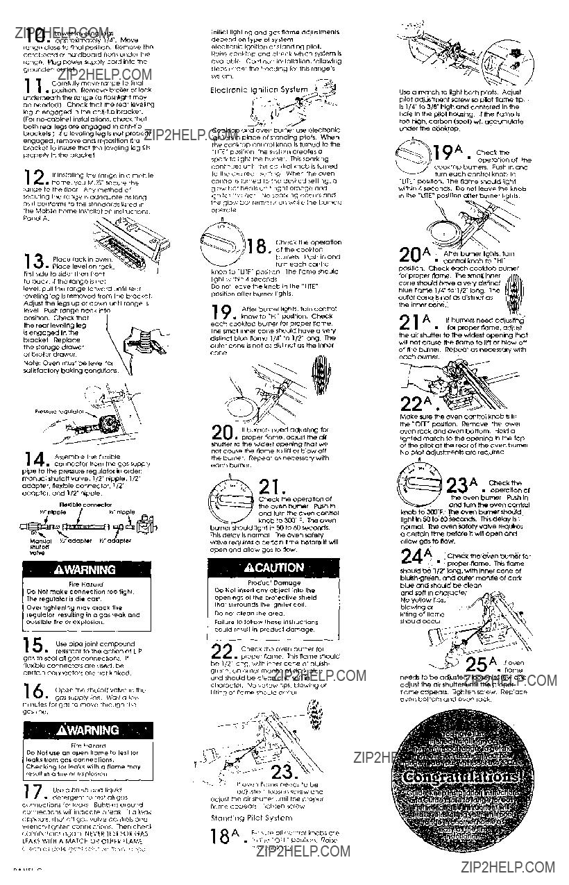
Use 0 match to liaht both 0llots. Adivst pilot adjustment screw so bllot Ram& tip Is l/4??? to 318??? hkrh and centered in the hole In the plfo<housing. If the name Is to0 high.carbon (soot) wnl
cooktop burners. Push ,n and turn each control knob to
???LITE??? poslHon. The flame should I,Qht within 4 seconds. Do not leove the knob in the ???LITE??? poslllon titer burner lights.
Make sure the ??????en control knob Is In the
No PIlot ???djustmenk ore required
.
23A.g::h&
needs to be adjusted. loosen screw and adjust the air shutter until the proper flame appears. Tighten zcrew Replace ??????en bottom and oven rack.

Conversion
should be done by a qualified installer.
Only a qualified A installer should
.. install or adjust your gas range.
Pressure Regulator: Use a wrench to unscrew the cao from
the top by turning counter-
clockwise. Turn the cap over so the hole end is up. Replace the cap and gasket on the regulator. DO NOT REMOVE THE
PRESSURE REGULATOR.
against pin. DO NOT OVERTIGHTEN.
Adjust the air shutters for proper flame by ??? sliding the air shutter to close or open the shutter as needed. See Panel C. step 19 for electrical ignition systems or Step 20A
for standing pilot systems,
Cooktop burners with standing pilots require adjustment of pllot flame to l/4 high. The adjustment control is located on the manifold pipe or at pllot flame base, depending on the model.
i???, _ P Oven Burner: Remove oven
b. racks and lower panel from oven bottom. Turn the orifice hood down until snug against pin. DO NOT OVERTIGHTEN. Tne burner flame should be l/2??? long when air shutter is correctly
adjusted. The air shutter slides to close or open the shutter as needed. See Panel C. Step 22 for electronic ignition systems, or Step 24A for standing pilot systems. Replace oven bottom and racks.
A MATCH OR OTHER FLAME.
.i_