Operating Instruction Manual
TOA POWERED MIXER
Model
TOA ELECTRICCO.,LTD.
KOBE, JAPAN
Operating Instruction Manual
TOA POWERED MIXER
Model
TOA ELECTRICCO.,LTD.
KOBE, JAPAN

 Contents
General Description
Features
Front Panel [Input Section]
Front Panel [Output Section]
Front Panel [Stereo Cassette Recorder Section] Front Panel [Patch Bay & Bus Link]
Rear Panel
Connection Examples
Input Connections
How to get a good mix.
Recording Level Setting
Type of Cassette Tape
Maintenance of Stereo Cassette Deck
Block and Level Diagrams
Specifications
Characteristic Diagrams
Appearance
 Precautions
1. XLR Type Audio Connector
The connectors are wired as follows.
The pin 1 is ground (shield), the pin 2 cold (low, minus), the pin 3 hot (high, plus).
2. Description of components and functions on the
Descriptions may vary, depending on each manu- facturer . In our Operating and I n s t r u c t i o n Manual explanation of components and f u n c t i o n s is made according to our usage for them.

A Few Words about design:
The MCX??? is quite an unusual product, but the reasoning behind its design was quite simple . . . . we wanted to intergrate all the basic components of a sound reinforcement system and a recording studio into a single, transportable package.
The basic components of the MCX??? are as follows:
1.
2.
3.
4.
5.Stereo tape deck.
6.
7.Patch bay.
8.Headphone c u e / m o n i t o r system .
9.
10.Road case.
Each of these "components" f u n c t i o n s independently of the others, a l t h o u g h some do share common signal
make use of t h e same i n p u t e q u a l i z a t i o n on each of the six channels. And the i n p u t trim control performs the same f u n c t i o n for all four mixing sections.
??? 1 ???

 General Description
The
The
Each input channel features: input trim control with LED peak indicator,
The
All these unique functions are integrated into a ruggedly construct and portable package, offering unlimited applications for school, church, band, performing group, etc.
The
 Features
1.
2.Six Input Channels
3.300 watt Power Amplifier
4.
5.
6.Reverberation Effect with
7.Fluorescent Bargraph Metering??? assignable
8.Power Amp Protection Circuitry with indicator
9.Complete patch Bay with
10.Aux. Input with Stereo Balance and Level Controls ??? assignable to PGM, FB, and Rec L & R Busses
11.Headphone Monitoring/Cueing System
12.Independent Stage Monitor (FB) Mix
Each Channel
1.Input Trim Control with LED peak indicator
2.
3.
4.
5.Post reverb/effects send
6.
7.
Stereo Cassette Recorder
1.Full Logic Cassette Mechanism Control
2.dbx?? Noise Reduction System
3.Automatic Tape Selector with Indicator (normal,
CrO2 Metal)
4.Headphone Output with Level Control
5.Tape Transport Remote Control (start/stop)
6.Tape Pitch Control (??10%)
7.Zero Return with Automatic Cue
8.
??? 2 ???

 Front Panel, Input Section
Foldback Control (FB)
The Foldback control deter- mines the level of signal assign- ed to the foldback mixing buss, thus setting the level of t h a t
channel in the
High Equalizer Control
(HIGH EQ)
The high EQ control alters the
high frequency response of the
input channel, providing ??13dB at 10kHz, and ??15dBat 20kHz of continuously variable active shelving equalization. The "0" detented position provides flat audio response.
Middle Equalizer Control
(MID EQ)
The mid EQ control provides ??15dB of continuously variable
active peaking equalization at
2kHz. and has a flat audio re- sponse when set to the "0" detented position.
Low Equalizer Control
(LOW EQ)
The low EQ control provides
??13dB at l00Hz and ??15dB at
50Hz (of continuously variable active shelving equalization .
The "0" detented position pro- vides flat audio response.
Reverb/Effects Control
(REV/EFF)
This control determines the?
level of signal assigned to the re- verb effects buss. Rotating the
control clockwise increases the amount of reverb effect in t h a t
channel.
Low Impedance Connectors
(LOW Z)
The XLR connectors are low im-
pedance, electronically balanced
Peak Indicator (PEAK)
The peak indicator lights when
the pre or post EQ signal level reaches 3dB below clipping, giving a visual reference for optimum s e t t i n g of the trim con- trol.
High Impedance Connectors
(HIGH Z)
These connectors are unbalanc- ed, standard 1/4" phone jacks with an input impedance? of 50k ohms, and an i n p u t level of
Input Trim Control (TRIM)
The input trim adjusts the gain of the
sociated channel, providing 39
dB of gain control. When the trim control is set to the "10" position, the nominal input
levels of the
inputs are
spectively. At the "0" position
the levels are
flashes occasionally. This will ensure lowest distortion levels and optimum signal to noise ratio.
Recording pan Pot (REC PAN)
This control assigns the record- ing signal from each channel to
the recording L and R mixing
busses. At the center position,
the pan pot routes the signal
equally to the L and R mixing busses. Panning from one side to
the other gradually assigns the input signal to either the record- ing L or R mixing bus exclusive- ly!
Recording Level JControl
(REC LEVEL)
This control adjusts the level of signal assigned to the tape deck via the recording pan pot and stereo L and R recording busses. Rotating the control clockwise increases the amount of signal assigned to the recording L and R
busses and thus the level of that input in the "recording mix."
program mixing buss, thus de- termining the level of that channel in the main sound system mix. Since the reverb/ e f f e c t s signal is "post" this con- trol, an increase in the level of the
channel's o u t p u t will also result
in a corresponding increase in he reverb effect of that channel. The nominal level of the input level control is at the "10" posi- tion.
??? 3 ???

 Front Panel, Output Section
Aux Recording Balance
(AUX REC BAL)
This control adjusts the level balance of the aux in, L and R signals routed to the L and R mixing busses.
At the center position, the bal- ance control routes the signal
equally to the L and R mixing busses.
Reverberation High Equalizer ???
Control
(REV HIGH EQ)
The high EQ control alters the
high frequency response? of t h e reverberation signal. The "0" de- tented position provides flat audio response.
Recordig Level Control
(EFF REC LEVEL)
-Reverberation Low Equalizer Control
(REV LOW EQ)
reverberation signal. The "0" de- tented position provides flat audio response.
-Playback to Program Control
(TAPE TO PGM)
Foldback Master Control (FB)
The FB master control adjusts
the overall combined signal level of the six independent channel foldback sends, and
thus the level of the entire on- stage monitor mix.
Program Master Control (PGM)
The PGM control adjusts the
overall combined signal level of
Auxiliary Input Recording
Level Control
(AUX REC LEVEL)
This control sets the level of stereo L and R signal (from an
external source connected to the
AUX INPUT) assigned to the re- cording busses, via the AUX REC BAL control.
Auxiliary Input to Foldback Control ((AUX TO FB)
This control sets the level of aux input signal assigned to the fold- back mixing bus, and thus the level of the external aux source in the
NOTE: If the aux source is a stereo L and R signal (for example, a stereo casset- te player) the L and R will be combined into one mono signal before assignment to either the FB or PGM mixing bus- ses.
Auxiliary Input to Program
Control
(AUX TO PGM)
This control sets the level of aux input signal assigned to the program mixing bus, and thus the level of the external aux source in the main mix.
This control sets the level of reverb (or external e f f e c t s ) in
the recording mix, via the effects return pan pot.
Effect Recording Pan Control
(EFF REC PAN)
This control assigns the reverb
or external effects signal to the recording L and R mixing bus-
ses. In the center "detended"
position, the signal is assigned equally to L and R; panning the
control gradually assigns the
effect to either bus exclusively.
This control a d j u s t s the level of playback signal routed to t h e program mixing buss, and t h u s the level of the internal tape? source in the main mix.
Playback to Foldback Control (TAPE TO FB)
This control adjusts the level of
playback signal to the foldback mixing buss, and thus the level of the internal tape in t h e on- stage monitor mix.
the six independent channel
level controls, and thus the level of the main sound system.
Graphic Equalizer
(EQUALIZATION)
The graphic equalizer is 1/1
octave with 9 independent active bands (filters ) , providing 12dB
of boost or cut at each center fre- quency. The "0" detented posi- tion provides flat audio re- sponse.
Graphic Equalizer In/Out
Switch (IN/OUT)
The in/out switch enables com- parison between a flat response ( o u t ) and the equalized response (in) . The "out" position com- pletely removes the equalizer from the
Phones Level Control
(PHONES)
The phones level control adjusts both the recording L
and R signals fed to the phones
o u t p u t and permits recording and playback monitoring.
Headphone Jack
The headphone jack will accept any stereo headphone with 8 ohms impedance, or higher.
Tape Deck Remote Control
Effect to Foldback Control (EFF TO FB)
This control determines the level of reverb/effects return signal assigned to the foldback
Buss Link Jack (BUSS LINK)
Patching Jack (PATCH BAY/OUT)
Patching Jack (PATCH BAY/IN)
(TAPE REMOTE)
This jack remotely operates the tape PAUSE function during recording or playback by means
of a foot switch.
mixing buss, and thus the amount of effects in the
Reverb/Effects to Program- Control (EFF TO PGM)
This control adjusts the amount of reverb/effects signal t h a t is returned to the program buss and thus the level of reverb/ effects contained in the main sound system.
Reverb/Effects Send Control
(REV/EFF SEND)
This control adjusts the overall
signal level of the effects mix
the effects o u t p u t . The send con- trol works in conjunction w i t h
the REV/EFF to PGM and the REV/EFF to FB controls to set the overall level of reverb/ effects in the main and monitor
sound systems.
(AUX IN, L, R)
The aux L and R 1/4" phone jacks are unbalanced and a c c e p t low and high impedance sources at nominal
the aux input circuitry. The aux
input is intended primarily for
external music sources such as
The REC out pin jack derives its signal from t h e recording L and R mixing busses, and is intended for connection to external r e -
impedance o f 1k ohms.
Playback Output Pin Jack
(TAPE OUT)
The playback o u t pin jack obtains its signal from the
internal tape deck. Nominal
o u t p u t level is 0dB dB w i t h an impedance o f 1k ohms.
Power Amp Compression-
Indicator (COMP)
The comp LED lights when the internal compressor is a c t i v a t -
ed. The compressor is provided to protect speaker systems by
when clipping occurs in the o u t - put stage. Frequent flashing of t h e LED is not reason for alarm.
the;
Power Amp Protection
Indicator (PROTECT)
The indicator LED lights if the
power amplifier o u t p u t is short-
ed, if the temperature of the unit rises above acceptable levels, or if DG is drifted to the speaker outputs . If the LED should light, speaker wiring and ambient
temperature of the
should be checked. If the LED remains lighted, the unit should
be referred to qualified service personnel for repair.
Note:
The
ditions' w i t h i n the power amp- lifie r , (2) give a visual indication, and (3) a u t o m a t i c a l l y shut down
u n t i l the; fault condition is
alleviated. This special circuitry
e n s u r e s maximum reliability and virtually eliminates equip- ment damage due to unsafe or
i m p o r t a n t feature.
??? 4 ???
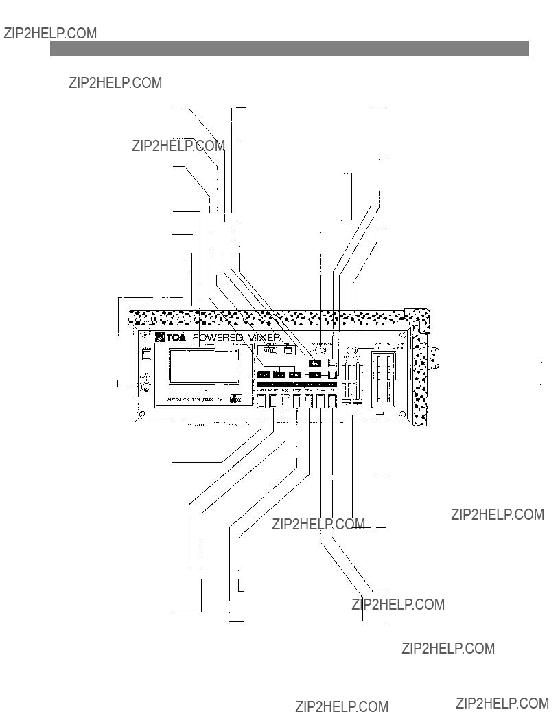
 Front Panel Stereo Cassette Deck Section
Counter Reset Button
Resets the tape couter to "000".
Tape Counter
Indicates how far the tape has travelled.
Tape Indicator
Indicates the type of tape used. (The deck automatically selects the type of tape. NORMAL, CrO2, METAL)
Cassette Receptacle
Eject Button (EJECT)
Ejects the tape.
Pitch Control
(PITCH CONTROL)
Varies the tape transport speed during playback by ??10%.
Mute Button
Pressing and holding the mute
button during tape travel (while
in the recording mode) will provide a "silent" section on the tape for use with the cuing function; releasing the b u t t o n will restore selected recording levels. It is essential that the "muted" section continue for at least four seconds to enable the cue function to operate cor- rectly.
Pause Button
This b u t t o n is used to stop the tape travel temporarily during recording or playback.
Recording Button
Pressing both the PLAY and this b u t t o n puts unit in the recording mode.
Cue Indicator
Remains l i t during operation of the Cue f u n c t i o n .
DBX Indicator
Lights when the dbx noise; reduction c i r c u i t r y is activated .
Zero Return Switch
This switch selects the zero return function . In the "on" position the tape will rewind and stop at any point on the tape t h a t you designate as "zero".
Rewind Button
Rewinds the tape at high speed.
Stop Button
Stops the t a p e motion .
DBX Button
Pressing this b u t t o n a l t e r n a t e l y
enables or disenables the inter- nal dbx noise reduction feature in either the playback or recording modes.
Cue Button
Pressing this b u t t o n and the FAST FORWARD or REWIND
b u t t o n will rewind the tape to the next "muted" or unrecorded section (tape silence of four
seconds or more), where the deck will automatically stop.
Level Meter Selector Switch
The left position monitors the
Fluorescent Bargraph Meter
The high i n t e n s i t y meters enable visual monitoring of the o u t p u t
signals selected with the Level
Meter Selector Switch.
Recording Level Sliders
Sets the overall signal level of
t h e stereo L and R recording
busses during the recording process; this includes the level assigned to the; REC OUT jacks as well as the; internal tape deck.
Fast Forward Button
Advances the; tape at highspeed.
Playback Button
This b u t t o n is used to playback
t h e tape;.
??? 5 ???
 Front Panel, Patch Bay & Buss Link
Effects Return Jack (EFT/RET)
The EFF/RET jack is provided to
connect an external effects
device to the
cally switched out of the MCX-
should be connected to the out - put of the external effects u n i t .
Nominal input level is
w i t h an impedance of 50k ohms.
Effects Output Jack (EFF)
The EFF Out jack used in con- j u n c t i o n with the EFF/RET Jack allows use of an external effects
out jack should be connected to the input of the external effect unit . Nominal o u t p u t level is
??? l0dB with an impedance of 600 ohms.
Graphic Equalizer Input Jack
(GEQ)
The GEQ i n p u t jack allows t h e
graphic equalizer to be used in-
dependently of the
w i t h other external e q u i p m e n t ,
plug is inserted, the main mix from the program buss is discon- nected from the graphic equal- izer and the power amplifier .
The nominal input level is
w i t h an input impedance of 50k ohms.
Power Amplifier Input Jack
(PWR)
The PWR Amp i n p u t jack allows
the internal power amplifier to be used w i t h e x t e r n a l equip- ment. When a plug is inserte d , the power amp is a u t o m a t i c a l l y disconnected from the
Program Buss Link Jack
(PGM) (+4dB 22k )
)
Fold Back Buss Link (FB)
(+4dB 22k )
)
Reverb/Effects Buss Link Jack
(EFF) (+4dB 22k )
)
Buss Link Jacks
The buss link provides direct access to the PGM, FB, and ef- fects mixing busses, and is pro- vided for easy input expansion w i t h additional
Program Output Jack -
(PGM)
The PGM Out jack is provided for connection to external equal-
izers and/or power amps, deriv-
ing its signal prior to the internal
GEQ and power amp. Nominal
o u t p u t level is +4dB with an
impedance of 600 ohms.
-Foldback Output Jack (FB)
This jack is for connection to
external power amplifiers and/
or equalizers for the
o u t p u t level is +4dB with an
impedance of 600 ohms. If the internal power amp and equal- izer are to be used for the on-
-Graphic Equalizer Output Jack
(GEQ)
This jack allows the
used independently of all other
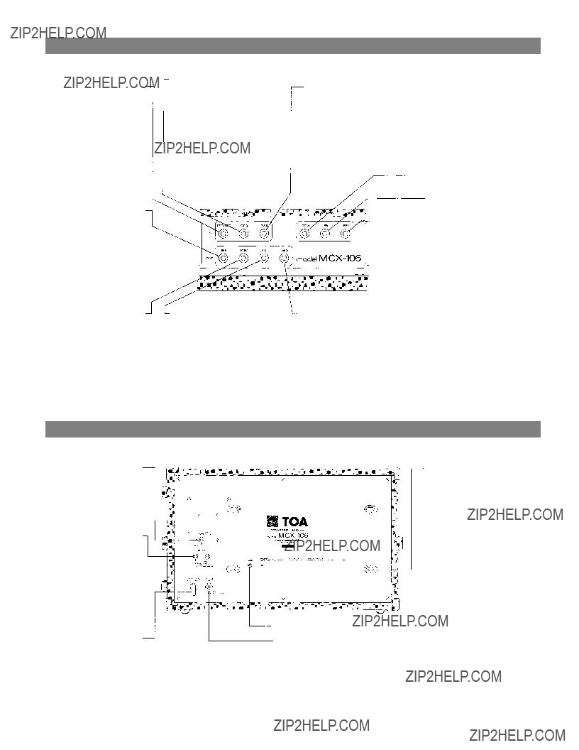
 Rear Panel
Power Switch (POWER) -
The power switch is a three-
position type w i t h the middle
position being the "off" position.
The
ed in the switch position which
produces the lowest amount of
system hum.
Speaker Jacks (SPEAKERS) -
The speaker o u t p u t s are stand- ard 1/4" phone jacks wired in parallel. Speaker cables (recom- mend at least #18 gauge wire) should be connected between
the
Earth Terminal (GND)
AC Fuse
t y p e and r a t i n g . Using improper
fuses will also void the warran-
Cord Wrap
The cord wrap is provided for convenient storage of the power cord when the
use.
Caution - The power cord should
always be completely removed from the cord wrap prior to operation of the u n i t . This will insure maximum cooling of the
panel and any other surface
106 are also provided for convec- t i o n cooling. These vents should be kept clear and open. Failure to do so may cause thermal shut - down of the u n i t .
t y . The
??? 6 ???

 Connection Examples
Low Z input should be connected
with low impedance (50 ohm ~ 600 ohm) microphones
MAIN MIXER
WIRELESS TUNER
SUCH AS
From Speaker Jack
on Rear Panel
KEYBOARD
MUSICAL INSTRUMENT
MAIN SPEAKER SYSTEM
SUB MIXER
B u i l t in Power
Amplifier for
Foldback
From Speaker Jack
on Rear Panel
HEAD PHONES
TAPE DECK
REMOTE CONTROL
FOOTSWITCH
SPEAKER SYSTEM
for foldback
_??? 7

 Input Connections
Generally speaking, there are two rules to follow when connecting equipment outputs
to the inputs of other equipment.
1.Properly match the impedances of the outputs and inputs.
2.Connect low impedance outputs to high impedance inputs.
It goes without saying that not only input and output impedance matching but also level matching should be taken into consideration. Each input channel of the MCX- 106 is provided with an input TRIM control, so the usable signal level range is very wide. Input impedances and levels are shown in the following table.
INPUT SPECIFICATIONS
*Sensitivity is the level required to produce a program out level of +4dBm. *0dBm is referenced to 0.775V RMS.
All XLR Type connectors are electronically balanced (transformer less). Phone jack is
unbalanced.
If the line going from one piece of equipment to another is long (more than 5m), we
recommend that balanced outputs be connected to balanced inputs.
As is described in the beginning of the Operating Instructions Manual, the connectors
of the
minus). Pin 3 is hot (high, plus).
??? 8 ???

 How to get a good mix
Before connecting other equipment to the Powered mixer, check the impedance and level of both. If the impedances and levels do not match, mixing will be very difficult and the S/N ratio will also be adversely affected.
Each input channel of the
The function of the TRIM control is to control the negative feedback volume of the
For example, a keyboard, a musical instrument and a dynamic microphone with output levels of
If the trim control is set as shown in the left figure, the input level controls can be set to the same position.
The input level controls are used in general between 6 and
8.
The peak indicator LED illuminates if the head amplifier or equalizer is clipping. The gain of the
must be decreased by turning the trim control counter- clockwise.
Fault Protection Table
 Recording Level Setting
The following procedures are recommended for an accurate and
1.Place the level meter selection switch in the "Tape" position.
2.Engage the noise reduction circuitry by pressing the dbx switch.
NOTE:
Using the internal dbx circuitry will provide higher quality recordings with excellent
an "encode/decode" process, meaning that any tape that is recorded with dbx must also be played back with dbx, to obtain satisfactory results. If the recording must be played on other equipment without dbx circuitr y , we recommend that the dbx feature not be used.
3.Press the record b u t t o n to place the deck in "record pause" mode.
4.Adjust the L and R master recording level sliders to
a level j u s t below the "red" in the bargraph meters. 5. Press PLAY b u t t o n to begin recording.
??? 9 ???
 Types of Cassette Tape
CAUTION:
A
NOTE:
The MCX detects the type of tape (Normal, CrO2 , Metal) when the cassette is inserted and the door is latched, automatically selects the proper EQ and bias settings, and gives a visual indication on the front panel.
For highest quality recordings and extended dynamic range, we recommend the use of metal tape whenever possible.
SAVING YOUR RECORDINGS
Cassette tapes are provided with two
overtaping, break the tabs with a
openings with adhesive tape if you desire to erase or record the tape at a later date.
Hints on Cassette Tape Handling
1.Tape Slack can cause the tape to twist or break. When necessary, always take up slack by inserting a pencil or similar object into the reel hub and turning.
2.Winding the tape too tightly on the reel may cause the tape to rotate unevenly; in worst case, the tape may bind and not wind from reel to reel.
Before using a tape again after continuous playback or recording, lightly tap the cassette housing or both sides, and if necessary, rewind the tape in either the
Storing Tapes
Always store cassette tapes in their cases with a protective insert over the exposed portion of the tape; if not available, attach a "stopper" made from paper as
shown in the illustration. To prevent damage or degradation of recordings, always store tapes in locations free from direct sunlight, high temperature or humidity, and magnetic effects from other electrical equipment, speaker systems, etc.
 Maintenance of Stereo Cassette Mechanism
Cleaning the tape heads
NOTE:
We recommend removal of the cassette receptacle door prior to the cleaning operation; this will facilitate easy access to all the inner workings of the tape transport assembly.
1.The cassette door opens when the EJECT button is pushed. After opening, press the door downward (see illustration) to disconnect the "top mounted
detents" which hold the door to the chassis. Now pull outward and away from the main assembly. Place the door aside in a safe location for later cleaning.
CAUTION:
To prevent damage to the transport and head assembly, use only cotton swabs or a soft cloth for the cleaning procedure.
2. Using any good grade of commercially available tape cleaning fluid (or an acceptable substitute such as alcohol), thoroughly clean the tape heads, tape guides, and all other metal parts in the tape path.
3.Clean the rubber parts of the transport assembly with cleaning fluid, or alcohol, and wipe dry with a clean, soft cloth.
NOTE:
If a transport "Lubricant" of any kind is used on the metal parts, take care to avoid contact with rubber parts.
CAUTION:
The tape heads and guides are carefully adjusted to ensure smooth and accurate tape travel during both recording and play back; DO NOT USE EXCES- SIVE FORCE when cleaning: misalignment may result.
We recommend through cleaning of the tape transport assembly after every four to six hours of use to ensure optimum recording and play back performance.
Demagnetizing the tape heads
The recording head will become "magnetized" after prolonged use. This residual magnetism will degrade and possibly destroy your valuable recordings by
available; follow the manufacturer's directions for use.
??? 10 ???

 Block and Level Diagrams
BLOCK DIAGRAMS
LEVEL DIAGRAM
??? 11 ???

 Specifications
MIXER SECTION
Frequency Response
+0,
Total Harmonic Distortion
0.05% +4dBm at 1kHz.
Hum and Noise (Open)
INPUT SPECIFICATIONS
POWER AMPLIFIER SECTION
Frequency Response
+0,
Rated Power & Load
Total Harmonic Distortion
Less than 0.1% (200mW~200W RMS, 20Hz~20kHz) Typically below 0.05%
Compressor Dynamic Range
Greater than 26dB
Hum and Noise
At least 110dB S/N ratio, 20Hz~20kHz At least 113dB S/N ratio
Damping Factor
Greater than 200 (1kHz
Input Sensitivity
+4dBm (1.23V)
Input Impedance
Output Connector
Phone Jack X2
Power Requirement
600 W 120V AC 50/60Hz
Dimensions (WXHXD)
605X371X356mm (23.8X14.6 X14.0) inch
Weight
27.2 kg (60 Ibs)
*0dBm is referenced to 0.775V RMS.
Specifications are subject to change without notice.
??? 12 ???

Specifications
STEREO CASSETTE DECK SECTION
Mechanism
1 Motor 3 Solenoid Mechanism
Control
4 Bit Micro Computer
Tape
Compact Cassette
Track Format
Heads
2 Channel Stereo Recording/Play Back (Permalloy)
Erase (Ferrite Double Gap)
Tape Speed
Motor
Electronically Governor
Frequency Response
40 Hz to 12.5 kHz (Metal) (Overall Record/Playback)
Noise Reduction
*DBX type II (IN/OUT Switchable)
Signal to Noise Ratio
70dB *DBX IN 20 Hz~20 kHz
90 dB *DBX IN
Total Harmonic Distortion
Less Than 3% at 1kHz 0dB
Bias Frequency
85kHz
 Characteristics Diagrams
??? 13 ???

 Characteristics Diagrams
Appearance
??? 14 ???

TOA ELECTRIC CO., LTD.
KOBE, JAPAN
Printed in Japan