
Maritime Radio Services Operation
Warning!
This transmitter will operate on channels/ frequencies that have restricted use in the United States. The channel assignments include frequencies assigned for exclusive use of the U.S. Coast Guard, use in Canada, and use in international waters. Operation in these frequencies without proper authorization is strictly forbidden. For frequencies/channels that are currently for use in the U.S. without an individual license, please contact the FCC Call Center at
For individuals requiring a license, such as commercial users, you should obtain a license application from your nearest FCC field office.


Uniden OCEANUS
The Uniden OCEANUS VHF marine radio transceiver has been designed to give you a rugged, reliable instrument that will provide you with years of
With proper care and maintenance, your Uniden OCEANUS will outlast your present vessel and serve you well
The technical excellence of the Uniden OCEANUS is demonstrated by the multiplicity of uses for which it has been found acceptable by the U.S. Federal Communications Commission. The Uniden OCEANUS is acceptable for compulsory use on ???party boats,??? for use on vessels subject to the Great Lakes Radio Agreement or
The Uniden OCEANUS is of all solid state design with conservatively rated, rugged components and materials compatible with the marine environment. The transceiver utilizes a number of gaskets, sealing rings, waterproof membranes, and other sealants to effect a splashproof housing for protection of the electronics. The unit may be mounted in any number of convenient locations on your vessel by utilizing the universal mounting bracket.
You are encouraged to thoroughly read the rest of this Operating Guide to acquaint yourself with the characteristics and operation of your transceiver so that you can contribute to the longevity of your investment.
Keep your receipt as
NOTE: ??? Features, specifications, and availability of optional accessories are all subject to change without notice.
??? The color of your OCEANUS may vary.
1
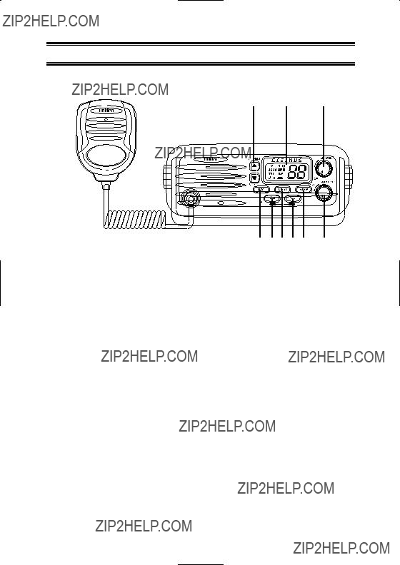
Controls and Indicators
Front Panel
1 2 3
10 
5 

 8
8
1.CHANNEL - This control is used to manually select the desired Communication Channel (01 - 28 and 60 - 88), or Weather Channel (0 - 9).
2.LCD Panel - Indicators for TX, SCAN, TRI, U, I, C, HI, LO, MEM, WX, WX ALERT, and Channel Number.
3.POWER/VOLUME (On/Off/Volume) - Turns the OCEANUS On or Off and varies the audio output.
4.WX (Weather mode On/Off)
5.16/9 (Channel 16/Channel 9; also located on microphone)
6.MEM (Memory)
7.H/L (Output Power Hi/Low)
8.STEP (also located on microphone)
9.SQUELCH - Eliminates background noise when no signal is being received.
10.Press - to - talk (PTT) Switch - Press to transmit and release to receive.
Note: Items 4 through 8 are
2

Rear Panel Connectors
11
1213 14
+13.8V 
 Ground
12.Antenna Connector - Connect the antenna here using a type PL259 connector.
13.Remote Speaker Connector - An external 4 ohm, 4 Watt speaker may be connected to this jack. The connecting wire must have a miniature plug.
14.DC Power and PA Speaker Output - The ???Pigtail??? cord and connector are power in and PA Speaker out.
Supplied Power Cord - Connect supplied power cord to the keyed connector.
3

16
15


2423
15.U (US) - Indicates US Channel Mode.
I (International) - Indicates International Channel Mode. C (Canada) - Indicates Canada Channel Mode.
16.TRI (Triple Watch) - Indicates Triple Watch Mode is in effect.
17.SCAN - Indicates Normal Scan Mode.
18.TX (Transmit) - Indicates transmitting.
19.HI (High) - Indicates transmitted output is 25 Watts.
20.LO (Low) - Indicates transmitted output is 1 Watt.
21.MEM (Memory) - Indicates Memory Scan Mode status for each channel selected.
22.LCD Numerical Channel Display - Indicates Channel Number in use. Weather Channels are displayed as single digits.
(Example: 0, 1, 2, 3, etc.) Communication Channels are displayed
as two digits (Example: 01, 02, 03, etc.).
Note: LCD Status Indicators appear when status is selected by pressing the corresponding button.
23.WX - Indicates Weather Channel Mode has been activated.
24. (Weather Alert) - Indicates Weather Alert mode.
4

45 6 7 8
4.WX (Weather) - This key is used to switch between monitoring weather channels and communication channels. This key is also used to activate the Weather Alert Mode.
???Press WX to switch between weather and communication channels.
???Press and hold WX to turn the Weather Alert Mode On/Off.
5.16/9 - This key is used to instantly access Channel 16 and Channel 9 communications. This key is also used to access Triple Watch, and when used in conjunction with MEM, this key lets you change between Channel Modes of Operation.
???Press 16/9 to access instant Channel 16/Channel 9 communications.
???Press and hold 16/9 to turn Triple Watch On/Off.
???Press MEM, then press 16/9 to switch between US, International or Canada Channel Modes.
5

6.MEM - This key enters channels in the Memory Scan Mode. When used in conjunction with H/L, the LCD Panel brightness can be adjusted. When used in conjunction with the 16/9 key, the Channel Mode of Operation can be selected.
???Press MEM to enter a selected channel in Memory Scan Mode.
???Press and hold MEM, then press H/L to adjust the LCD Panel light intensity from bright to dim. Repeat this action to return to the bright intensity setting.
???Press and hold MEM, and then press 16/9 to change the Channel Mode of Operation between US, International, or Canada.
7.H/L - This key is used to switch between HI (25 Watts) where allowed, or LO (1 Watt) output power. When pressed and held, this key activates the PA mode and, when used in conjunction with the MEM key, this key adjusts the brightness of the LCD Panel.
???Press H/L to switch between HI and LO output power.
???Press and hold H/L to access the Public Address Mode.
???Press and hold MEM, and then press H/L to adjust the brightness of the LCD Panel backlight.
The LCD Panel backlight indicator is at the brightest level when the OCEANUS is shipped from the factory.
8.STEP - This key is used to step through the channels entered in the Memory Scan Mode. When pressed and held, this key also starts and stops the SCAN Mode.
???Press STEP to step to a desired channel.
???Press and hold STEP to begin the Channel Scan Mode and initiate Triple Watch automatically.
6

Installation
Caution: The OCEANUS will only operate with nominal 12 volt negative ground battery systems.
It is important to carefully determine the most suitable location for your OCEANUS on your vessel. Electrical, mechanical, and environmental considerations must all be taken into account. You should select the optimum relationship among these considerations.
Keep in mind the flexibility designed into the OCEANUS so that
you can most conveniently use your radio. Features which should be considered are:
1.The universal mounting bracket may be installed on either the top or bottom of a shelf, on a bulkhead, or for overhead mounting.
2.The REMOTE speaker jack can be used with an auxiliary speaker.
3.All connections are
4.Front fire internal speaker allows convenient
Choosing a Location
Some important factors to consider in selecting the location for your
OCEANUS:
1.Select a location that is free from spray and splash.
2.Keep the battery leads as short as possible. Direct connection to the battery is most desirable. If direct connection cannot be made with the supplied power lead, any extension should be made with #10 AWG wire. Long extensions should use larger gauge wire.
3.Keep the antenna lead as short as possible. Long antenna leads can cause substantial loss of performance for both receiving and transmitting.
4.Locate your antenna as high as possible and clear from metal objects. The reliable range of coverage is a direct function of the antenna height.
5.Select a location that does not allow the radio to be subjected to direct sunlight (including that coming through windows).
6.Select a location that allows free air flow around the heat sink on the rear of the radio.
7.Select a location well away from the ship???s compass. Auxiliary speakers also should be located away from the compass.
7
Engine Noise Suppression
Interference from the impulse noise generated by the electrical systems of engines is sometimes a problem with radios. The OCEANUS has been designed to be essentially impervious to ignition impulse noise and alternator noise. However, in some installations it may be necessary to take measures to further reduce the effect of noise interference. All DC battery wires, antenna lead, and accessory cables should be routed away from the engine and engine compartment, and from power cabling carrying high currents.
In severe cases of impulse noise interference, it may be necessary to install a noise suppression kit. Contact your Uniden Dealer for more information.
Antenna Considerations
A variety of antennas are available from a number of quality suppliers. It is recommended you draw upon the advice of your Uniden Dealer in determining a suitable antenna for your vessel and range requirements.
In general, communication range is increased by using a
8

Installing the OCEANUS
After you have carefully considered the various factors affecting your choice of location, position the radio (with the bracket, microphone, power cord, antenna and any auxiliary cables installed) into the selected location to assure there is no interference with the surrounding items. Mark the location of the mounting bracket. Remove the bracket from the radio and use it as a template to mark the holes to be drilled for the mounting hardware. Drill the holes and mount the bracket with hardware compatible with the material of the mounting surface.
Note: This HEXAGON HEAD BOLT is only for mounting the bracket with hardware. Do not use it for installing the radio in the mounting bracket.
Connect the red wire of the supplied power cord to the positive (+) battery supply. Connect the black wire of the power cord to ground. The power cord is equipped with a fuse to protect the radio. Use only a Six
(6) Ampere fast blow fuse for replacement. Connect the power cord to the keyed connector on the power ???pigtail???.
Connect the antenna and all other auxiliary cables and accessories.
Install the radio in the mounting bracket and connect all cables and accessories to the appropriate jacks and connectors.
Note: Do not use any other mounting knobs than the ones enclosed. Do not insert the knobs without attaching the bracket.
9

Operation
1.Turn the unit on by rotating the power/volume control clockwise.
2.Adjust the SQUELCH control counterclockwise until you hear background noise, and then turn it clockwise just until the noise disappears.
Triple Watch
Triple Watch monitors Channel 16 and Channel 9 for activity every two seconds while scanning or monitoring.
To activate Triple Watch, press and hold 16/9 until two short beeps are heard. The TRI indicator appears on the LCD panel, indicating Triple Watch mode is in effect. If a signal is received on either Channel 16 or Channel 9, the radio remains on that channel until the signal ends.
Press and hold 16/9 until a tone is heard to cancel Triple Watch Mode.
Manual Tuning
To manually select a channel, press the CHANNEL ???/??? buttons (???/???) to select the desired channel. Weather Channels are located on Channels 0 - 9. Communication Channels are located on Channels 01 - 28 and 60 - 88.
Instant Channel 16/Channel 9 Communications
To access instant Channel 16 or Channel 9 communications, press 16/9. This overrides the channel selected with the CHANNEL ???/??? selector buttons or any scanning activity. The Channel Display indicates the unit is on Channel 16. Press 16/9 again to access Channel 9 communications. Press and release 16/9 a third time to release the switch (Off). The transceiver will return to the channel selected prior to accessing instant Channel 16/Channel 9 communications. The Channel Display will indicate the selected channel.
10

To cancel Channel 16/Channel 9 communications:
???Press 16/9 until previous channel setting appears.
???Press WX.
Weather Scan
To scan only Weather Channels 0 - 9, press WX, and then press and hold STEP. The WX indicator will appear on the LCD Panel, indicating Weather Mode.
To exit from Weather Scanning:
???Press and hold STEP to end scan.
???Press 16/9 to change to Channel 16/Channel 9 communications.
???Press WX to change to standard channel communications.
US/International/Canadian Channels
To select operation (communication and scanning) on US Channels, press MEM, then press 16/9 while holding MEM. U (USA),
I (International), or C (Canadian) will appear on the LCD Panel.
Select the appropriate mode for operation.
MEM (Entering channel numbers into Memory Scan)
You can enter channels into Memory Scan for instant scanning at any time. When a channel is selected for Memory Scan, the MEM indicator will appear on the LCD display.
To enter a channel number into Memory Scan, select the channel number you want stored by pressing the CHANNEL ???/??? button, and then press MEM.
Note: In order for all functions of the OCEANUS to work properly, at least two channel numbers must be entered into Memory Scan before operating the radio.
11

Memory Scan
To scan channels stored in Memory Scan, press and hold STEP. In the Memory Scan Mode, the OCEANUS scans only those channel numbers previously entered into Memory Scan. If no channel has been entered into Memory Scan, an error tone sounds and the LCD Panel does not change.
Note: While in Memory Scan Mode, pressing the 16/9 button three times or pressing and holding STEP will return the radio to the channel it was on prior to accessing Memory Scan.
Public Address
To access the Public Address Mode, press and hold H/L. The PA icon will appear in the display. Press the PTT switch on the microphone, hold the microphone approximately two inches from your mouth, and speak clearly in a normal voice. To cancel PA, press and hold H/L.
Weather Alert
The Weather Alert Mode can be activated to alert you of dangerous weather. When Weather Alert is turned on, and a warning signal is received, a siren will sound at full volume, regardless of the volume setting. When the signal stops, you will hear the active weather channel broadcast at normal volume.
The  icon indicates the Weather Alert Mode is activated. To activate the Weather Alert Mode:
1.Press WX to select Weather mode press and hold WX.
2.Press and hold STEP to begin Weather Channel Scan.
1.Manually select the active Weather Channel after selecting WX.
2.Press and hold WX to activate the Weather Alert Mode. To cancel the Weather Alert Mode, press and hold WX again.
12

Transmitting
When the power is turned on, the transmitter is set for 25 Watts (except for USA Channels 13 and 67, and CANADA channels 13, 15, 17 and 20). The HI indicator will appear on the LCD Panel, indicating 25 Watt output power. In order to comply with FCC Regulations contained in 47 CFR 80.215 (g) (3), USA Channels 13 and 67 transmit at 1 Watt regardless of the H/L selector setting. However, 25 Watt output for emergency use is available by pressing H/L while pressing the PTT switch. When the H/L switch is released, the radio returns to the
1 Watt position.
To switch to the LO (1 Watt) position, press H/L. The LO indicator will appear on the LCD Panel, indicating 1 Watt output power. The LO position should always be used for
Press H/L to switch to the HI (25 Watt) position. The HI indicator will appear on the LCD Panel, indicating 25 Watt output power.
To activate the transmitter, press the PTT switch on the microphone. The TX indicator appears on the LCD Panel, indicating a signal is being transmitted. Release the switch to receive. When transmitting, hold the microphone approximately two inches from your mouth and speak clearly in a normal voice.
Note: You cannot transmit on Weather Channels 0 - 9 or Channel 15. The Channel Number in the LCD Panel will blink to indicate these channels are
Dimming the LCD Display Backlight
When the OCEANUS is turned on, the LCD Panel will be brightest. Pressing the MEM and H/L buttons will change the brightness.
The last setting will remain in memory. When you turn on the radio the next time, the display will be at this setting.
Transmitter
If the PTT switch on your microphone is held for more than
13

VHF FM Marine Radio Telephone
Channel and Functions
(USA Channels)
14

VHF FM Marine Radio Telephone
Channel and Functions
(International Channels)
15

VHF FM Marine Radio Telephone
Channel and Functions
(Canadian Channels)
16

Specification
17
Troubleshooting
If the OCEANUS does not perform to your expectations, try the suggestions listed below. If you cannot get satisfactory results, call the Uniden Customer Service Center at (800)
18

Care and Maintenance
Your OCEANUS is a precision piece of electronic equipment and you should treat it accordingly. Due to the rugged design, very little maintenance is required. However, a few precautions should be observed:
???If your radio has been accidentally subjected to spray or splash, you should immediately wipe it down with a soft cloth dampened with fresh water.
???If the antenna has been damaged, you should not transmit except in the case of an emergency. A defective antenna may cause damage to your radio.
???You are responsible for the continued FCC technical compliance of your radio.
???You are urged to arrange for periodic performance checks with your Uniden Marine Dealer.
19

Three Year Limited Warranty
WARRANTOR: UNIDEN AMERICA CORPORATION (???Uniden???)
ELEMENTS OF WARRANTY: Uniden warrants, for three years, to the original retail owner, this Uniden Product to be free from defects in materials and craftsmanship with only the limitations or exclusions set out below.
WARRANTY DURATION: This warranty to the original user shall terminate and be of no further effect 36 months after the date of original retail sale. The warranty is invalid if the Product is (A) damaged or not maintained as reasonable or necessary, (B) modified, altered, or used as part of any conversion kits, subassemblies, or any configurations not sold by Uniden,
(C) improperly installed, (D) serviced or repaired by someone other than an authorized Uniden service center for a defect or malfunction covered by this warranty, (E) used in any conjunction with equipment or parts or as part of any system not manufactured by Uniden, or (F) installed or programmed by anyone other than as detailed by the Operating Guide for this product.
STATEMENT OF REMEDY: In the event that the product does not conform to this warranty at any time while this warranty is in effect, warrantor will repair the defect and return it to you without charge for parts, service, or any other cost (except shipping and handling) incurred by warrantor or its representatives in connection with the performance of this warranty. THE LIMITED WARRANTY
SET FORTH ABOVE IS THE SOLE AND ENTIRE WARRANTY PERTAINING
TO THE PRODUCT AND IS IN LIEU OF AND EXCLUDES ALL OTHER
WARRANTIES OF ANY NATURE WHATSOEVER, WHETHER EXPRESS,
IMPLIED OR ARISING BY OPERATION OF LAW, INCLUDING, BUT NOT
LIMITED TO ANY IMPLIED WARRANTIES OF MERCHANTABILITY OR
FITNESS FOR A PARTICULAR PURPOSE. THIS WARRANTY DOES NOT
COVER OR PROVIDE FOR THE REIMBURSEMENT OR PAYMENT OF INCIDENTAL OR CONSEQUENTIAL DAMAGES. Some states do not allow this exclusion or limitation of incidental or consequential damages so the above limitation or exclusion may not apply to you.
LEGAL REMEDIES: This warranty gives you specific legal rights, and you may also have other rights which vary from state to state. This warranty is void outside the United States of America.
PROCEDURE FOR OBTAINING PERFORMANCE OF WARRANTY: If, after following the instructions in this Operating Guide you are certain that the Product is defective, pack the Product carefully (preferably in its original packaging). Include evidence of original purchase and a note describing the defect that has caused you to return it. The Product should be shipped freight prepaid, by traceable means, or delivered, to warrantor at:
Uniden America Corporation
Parts and Service Division 4700 Amon Carter Blvd. Ft. Worth, TX 76155
(800)

Thank you for purchasing a Uniden Marine Radio.
?? 2002 Uniden America Corporation, Fort Worth TX All rights reserved.
Printed in the Philippines UTZZ01881BA