TOSHIBA
STORAGE DEVICE DIVISION
PRODUCT SPECIFICATION
MARCH 2003
REV. 1.0
Specifications are subject to change without notice
DOCUMENT NUMBER 16004
TOSHIBA
STORAGE DEVICE DIVISION
PRODUCT SPECIFICATION
MARCH 2003
REV. 1.0
Specifications are subject to change without notice
DOCUMENT NUMBER 16004

LIMITATION OF LIABILITY
Those warranties in the express warranty separately agreed between TOSHIBA and your company are the only warranties given to the consumer and are in lieu of any other warranties, whether express or implied with regard to this component. TOSHIBA expressly and unequivocally disclaims the warranties of merchantability and fitness for a particular purpose.
Further, TOSHIBA disclaims all express warranties created by any individual or entity installing this device into a computer unless such express warranties are made with the prior express written consent of TOSHIBA or its authorized representatives.
TOSHIBA will not be responsible for any damages, whether compensatory, incidental, consequential, or special damages of any kind, including but not limited to, punitive or exemplary damages, treble damages, loss of use or lost profits whether such damages are sought by the
It shall be the responsibility of the purchaser herein to provide the
Warnings:
This equipment (an optical disc drive) handled under the conditions out of equipment specifications
may cause heavy load, heat generation, malfunction, erroneous operation and performance degradation. Therefore, please handle this equipment properly in compliance with the warnings provided below. In the event that you do not comply with the warnings, Toshiba cannot guarantee the safety, reliability and performance of the equipment expressly provided in the specification. Manufacturers and resellers
of the computer system using this equipment and/or this equipment itself shall notify the
1.This equipment does not involve any
2.DO NOT disassemble or modify this equipment. Toshiba shall not make any guarantee to the reliability, safety and performance of this equipment expressly provided in the specification and nor be liable fo
r any damages resulting from such unauthorized disassembly or modification.
3.Read carefully and comply with this Product Specification in order to avoid the risk of data error in writing operation. Such possible data error would be made by any factors other than this equipment (i.e., poor storage media, misuse of this equipment, malfunction in a computer system connecting this equipment, etc.). Toshiba shall not be liable for any damages resulting from such data loss. Check whether the original data is correctly copied or stored upon completion of writing operation.
Take any necessary measures to protect your data such as system backup and/or mirroring disk subsystems in order to avoid the risk of unexpected data loss or data corruption resulting from failure in this equipment for some reasons.
Manufacturers and resellers of the computer system using this equipment shall be required to consider the safety of such computer system and data integrity in order to avoid the risk of any consequential damages caused by data loss or data corruption and any problems or accident caused by malfunction of the computer system.

DO NOT use this equipment in the system such as medical equipment which may cause personal injury or property damages resulting from malfunction of this equipment and unexpected data corruption or data error in reading operation.
4.Turn off the power for this equipment and wait more than one (1) minute before you eject the disc using the emergency eject mechanism when a disc cannot be ejected for some reasons in order to avoid the risk of damages to the disc.
Notice
1.Turn off the system power before mounting/removing this equipment in order to avoid the risk of damages to this equipment.
2.Insert the DC power plug in correct direction in order to avoid the risk of damages to this equipment.
3.Handle this equipment only in electrostatically safe environment and do not touch connecting terminals with empty hands when you build in or pull out this equipment from other product in order to avoid the risk of malfunction of this equipment.
4.DO NOT do any of the following:
4.1.DO NOT use storage media (CD's / DVD's) that are not the correct size or shape, or do not meet the minimum formatting requirements set forth in section 3.1.(1) of this Product Specification.
4.2.DO NOT insert more than one (1) CD or DVD disc into the drive at any time. Doing so will damage or destroy this equipment and could damage or destroy the disc or cause data loss or corruption.
4.3.DO NOT load or eject any CD or DVD disc with force. Doing so will damage or destroy this equipment and could damage or destroy the disc or cause data loss or destruction.
4.4.DO NOT eject a CD or DVD disc while the drive is in operation. Doing so will damage or destroy this equipment and could damage or destroy the disc or cause data loss or corruption.
4.5.DO NOT insert anything else into the drive other than a CD or DVD disc. Doing so will damage or destroy this equipment.
5.When you close the tray, power must not be turned off. If the tray is pushed in with the hand during power off, a breakdown may occur because the mechanism in the product is not in the transit state during power off.

6.As for mounting bracket to incorporate this product into an equipment,
(1)When this product is incorporated into an equipment by using the mounting screw holes in the right and left side planes, the clearance between this product and the mounting bracket is too wide;
(2)When this product is incorporated into an equipment by using the mounting screw hole in the bottom, the surface of the mounting bracket is contorted.
If you use such mounting bracket as the above, this product will become deformed, which may cause operation failure. Therefore, it is necessary to take account of the mounting bracket which has the tolerances shown in Fig.1 or whose structure cannot cause this product to deform, as shown in Fig.2
less than plane 0.5
Select screws, the length of which threaded
onto the product is within 3 +/- 0.5 mm
Fig.1
this product
before the fixing
When a large amount space is left, insert spacers, etc. to adjust the space less than 0.5 mm between the product and mounting bracket.
after the fixing
mounting bracket
Fig.2

7.In the market, there are some drives or players that maintain to read CD or DVD disc, though, they may not designed to read
When you try to read the
8.In the instruction manual of your product, statement described in ???Safety Instruction Manual ???attached to this product, the statement described in " Cautions " above, the statement of item 4 and 5 above, and other required statements should be mentioned for thorough understanding by the users.
Please notify below notice to your customers.
Notice
Copyrighted works including, but not limited to music, video, computer program, database are protected by copyright laws. Unless specifically permitted under applicable copyright laws, you cannot copy, modify, assign, transmit or otherwise dispose of any copyrighted work without the consent of the owner of the copyright.
Please take notice that unauthorized copying, modification, assignment, transmission and other disposition may be subject to claims for damages and to penalties.


1. Introduction
This document describes TOSHIBA's
2. Features
This drive reads DVD CSS (Contents Scramble Systems) Disc.
This drive reads digital data stored on
This drive reads digital stored on
This drive corresponds to 4.3GB disc (single side) / 9.4 GB disc (double side) at time of reading
This drive records (write once) digital data on
This drive writes / rewrites digital data on
This drive supports
This drive shows a highest performance such as 100,000 hour MTBF.
This drive adopts
This drive support "Buffer underrun prevention" function.
Note:
Maximum storage capacities are 4.38 GBytes and 15.9 GBytes for single layer/single side and dual layer/double side respectively. (1 GByte=230 Bytes)

(4)Data Capacity (1 GB=230 Byte, 1 MB=220 Byte, 1 KB=210 Byte) User Data/Block

*1: All disc written in CD or DVD formats, except
these data formats. However, in order to run applications that use these formats you must first have the required software and/or hardware.
*2: Measured by performing multiple accesses which means reads of data blocks over whole area of the media from 0 (h) Frame to 1E7725(h) (4.089 Billion Byte:87 % of total area) Frame more than 3000 times. Includes positioning, setting, latency time and ECC implementation time (if required).
*3: Measured by performing multiple accesses which means reads of data blocks over whole area of the media from 00 min 02 sec 00 Frame to 60 min 01 sec 74 Frame (552.96 Million Byte:87 %
of total area at linear velocity of 1.3 m/s) more than 3000 times. Includes positioning, setting, latency time and ECC implementation time (if required).
*4: Measured by perfoming multiple accesses which means reads of data blocks over whole area of the media from 0 (h) Frame to 1E7725(h)
*5: Measured by performing multiple seek which means seeks of data block over whole area of the media from 0(h) Frame to 1E7725(h) Frame more than 3000 times.
Includes positioning, setting time which is same definition as HDD.
*6: Measured by performing multiple seek which means seeks of data block over whole area of the media from 00 min 02 sec 00 Frame to 60 min 01 sec 74 Frame more than 3000 times. Includes positioning, setting time which is same definition as HDD.
*7: Measured by performing multiple seek which means seeks of data block over whole area of the media from 0(h) Frame to 1E7725(h)
*8: Measured by performing maximum accesses which means reads of each data block of 0 (h) Frame and 1E7725(h) Frame alternately more than 100 times.
Includes positioning, setting, latency time and ECC implementation time (if required)
*9: Measured by performing maximum accesses which means reads of each data block of 00 min 02 sec 00 Frame and 60 min 01 sec 74 Frame alternately more than 100 times.
Includes positioning, setting, latency time and ECC implementation time (if required)
*10: Measured by performing maximum accesses which means reads of each data block of 0(h) block to 1E7725(h)

3.2. Environmental Conditions
This drive should be used under the conditions listed below.
*2: Packed in Toshiba original shipping package.


3.3.Installation Conditions
Mount the drive within 20?? of the horizontal positions and
within 10?? of the vertical positions
a) Horizontal position
b) Vertical position

+0.7 189.5
(Unit:mm)
Figure

(Unit:mm)
Figure

3.5.Reliabilites
3.5.1.Error Rate
(1)Hard Read Error Rate (Byte Error Rate)
4.1.Electrical Circuits
(1)Tray Eject Switch and Eject Detection Switch
(2)Optical Pickup Servo Drive Circuit
(3)Feed Motor Drive Circuit
(4)Laser Diode Control Circuit
(5)
(6)EFM Demodulator, Error Correction Circuit and DA converter (CD)
(7)IDE/ATAPI Control and
(8)CIRC Encoder
(9)EFM Encoder
(10)
(11)ATIP Demodulator
(12)LPP Demodulator
(13)Disc Moter Control Circuit

0.1.Rev
TA1365AF
TC94A38F
DRAM (16M)
Headphones (Option) 

Digital
Audio
Muting
Analog
Audio
+5V

+12V


5.Functions
5.1.Disc Data Configurations
5.1.1.
Figure 4 shows how data is constructed in the case of dual layer/parallel track data DVD disc.
The DVD spec defines the single layer, the dual layer/opposite and parallel track disc, that the
1 block=1/676 s
ID Data (Dual layer Parallel track path)
~~ Approx. 130 k
Figure 4
5.1.2.
Figure 5 shows how the data is structured in program units 1 block=1/75 s
4 bytes
~
~
Minutes
Second(0~59)
Blocks(0~74)
Mode
Figure 5

5.1.3.
ATIP is abbreviation of "Absolute Time In
(Address information is
Figure 6 shows the composition of ATIP.
n Address
n+1 Address
n+2 Address
Synchronization (4 bit)
Figure 6
After Writing
Data are written in CD format synchronizing with ATIP.
5.1.4.
Figure 7 shows the ECC block address stricture.
ECC block address
(N)
16 bytes
ECC block address (N+1)
16 bytes
ECC block address (N+2)
16 bytes
ECC block address (3 bytes)
Parity A
(3 bytes)
Field ID
(1 bytes)
Disc information or ECC block address
(6 bytes)
Parity B (3 bytes)
Figure 7 ECC block address structure of
After writing
The data is written in
5.2.Power ON/OFF Timing (Target)
Figure 8 shows the initialization sequence
Power ON or
System
Initialization
Focus Search
Spindle ON
Max. 550 ms
"Command" Receivable
Learning
"TEST UNIT
READY"
Command
Figure 8 Initialization Sequence
6. Interface
(1)The interface is based on T13/1321D (AT Attachment with Packet
(2)66 (ATAPI, ATA) commands are usable.
(3)The 2 MByte data buffer handles both high speed and low speed data transmission.
(4)The largest block size on playback is 2,647 Bytes.
The data length for each block is changeable by command.
6.1.I/O cable
Table1 shows the cable parameters.

6.2.Signal summary
The physical interface consists of single ended TTL compatible receivers and drivers
communicating through a
6.2.1. Signal Specification
Figure 9 shows the Signal Specifications
Figure 9 Signal Specifications

6.2.2. Timing of Host Interface (PIO)
Figure 10 shows the Host Interface Timings.
t0
Address valid*1
t2
t1
Write data valid*2
t9
t2i
t8
 t3
t3 
t5 t6Z
IOCS16-
tA
IORDY
tB tRD
*1:Device Address consists of signals
Figure 10 Host Interface Timing

6.2.3.Timing of Host Interface (DMA Multi)
Figure 11 shows the Host Interface DMA multi word Timings
t0
DMARQ
*1: In all timing diagrams, the low line indicator negated, and the upper line indicators asserted.
Figure 11 Host Interface Timing (DMA Multi)

6.2.4.Timing of Host Interface (Ultra DMA )
Figure 12 shows the Host Interface Ultra DMA word Timings
tZIORDY
In all timing diagrams, the low line indicator negated, and the upper line indicators asserted.
Figure 12 Host Interface Timing (Ultra DMA)

6.3.Connector
Figure 13 shows the mixture connector (Interface/Power supply) Table 2 shows Interface connector pin assignment.
power supply connector
DIGITAL AUDIO
CONNECTOR
Figure 13

Table 2 Interface Connector PIN Assignment

6.4. Support Command List
ATAPI Packet Commands

ATA Commands

8.CD Audio (Test condition: Ordinary temperature)
8.1. Analog Out
8.2.Digital Out
(1)Output Level
(2)Type
(3)Load Impedance
8.3.Connector
4P connector and 2P connector.
Digital Audio
#2 #1
Digital out GND
0.50 V
Unbalanced
75 OHM
Analog Audio
R GND GND L
Figure 14
8.4.Audio Modes
(1)16 Modes including 'Stereo', 'Lch Mono', 'Rch Mono' and 'Mute' are selectable by command. Default mode is 'Stereo'. Audio out is automatically muted in the digital data area and seek state.
(2)16 Steps of attenuation level for the Audio Output is selectable by command.
Default level is 0 dB.
8.5. Headphones Output (Option).....in case of the attenuator set at 0 dB by the command.....
8.5.1.Connector
3.5mm dia. Stereo Headphones Jack.
9. Device Configuration Jumper
9.1.Device configuration jumper (MODE SELECT)
The device configuration jumper is a
Figure 15
(a)Use CS (CSEL)
The device shall use the host interface signal CSEL to configure the device.
(b)MA (Master): Default Position
The device shall use for the Master. Default Mode is 'MA'.
(c)SL (Slave)
The device shall use for the Slave.
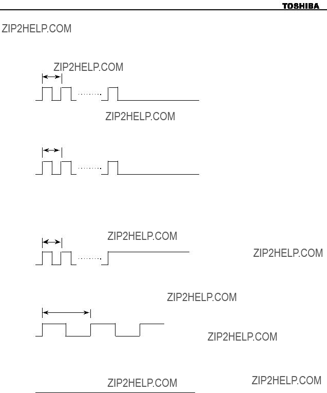
10. Busy Indicator
The LED of Front Bezel indicates the drive status. (Busy Indicator) Color: Green
(1) After Tray is closed, Busy Indicator start blinking at 0.8 s intervals, and then
0.8 s
Light Off
Figure 16 Idle
0.8 s
Light Off
Figure 17 No disc
0.8 s
Light On
Figure 18 Media Problem
(2)When playing an audio track, Busy Indicator is blinking at 1.6 s intervals.
1.6s
Figurer 19
(3)When performing 'Data Access' and during 'Data Transfer' and 'Write', Busy Indicator keeps turn on.
Light On
Figurer 20 Data Access and Data Transfer

12.Emergency Eject
Execute following procedure only in the case of emergency (Tray will not eject and disc can not be removed although pressing Eject Button).
(1)Turn the drive supplying power off.
(2)Insert solid bar (like paper clip) into Emergency Eject hole and push as shown in Fig.21. Then Tray will be ejected.
(3)After removed the disc, gently push Tray to close.
50 mm
diameter 1.0 to 1.5 mm
Figurer 21 Insert the bar

17.CE Declaration of conformity
Please refer to attached Annex 1.

This declaration certifies compliance with the listed directives, but does not constitute an assurance of characteristics.
The safety information in the supplied product documentation must be observed.
...........................................................................................................................................................
Document No.:YEA - R3457Page: 1 of 2
............................................................................................................................................................
Annex 1

29/29
0.1.Rev

23.1.Performance
(2) Applicable Write Disc
