FILE NO.
SERVICE MANUAL
Indoor Unit
<High Wall, Heat Pump Type>
SPLIT TYPE
Outdoor Unit
<Heat Pump Type>
R410A
PRINTED IN JAPAN, Nov.,2005 ToMo
FILE NO.
SERVICE MANUAL
Indoor Unit
<High Wall, Heat Pump Type>
SPLIT TYPE
Outdoor Unit
<Heat Pump Type>
R410A
PRINTED IN JAPAN, Nov.,2005 ToMo
CONTENTS
??? 2 ???

1. SAFETY PRECAUTIONS
For general public use
Power supply cord of outdoor unit shall be more than 1.5 mm 2
???Read this ???SAFETY PRECAUTIONS??? carefully before servicing.
???The precautions described below include the important items regarding safety. Observe them without fail.
???After the servicing work, perform a trial operation to check for any problem.
???Turn off the main power supply switch (or breaker) before the unit maintenance.
CAUTION
New Refrigerant Air Conditioner Installation
???THIS AIR CONDITIONER ADOPTS THE NEW HFC REFRIGERANT (R410A) WHICH DOES NOT
DESTROY OZONE LAYER.
R410A refrigerant is apt to be affected by impurities such as water, oxidizing membrane, and oils because the working pressure of R410A refrigerant is approx. 1.6 times of refrigerant R22. Accompanied with the adoption of the new refrigerant, the refrigeration machine oil has also been changed. Therefore, during installation work, be sure that water, dust, former refrigerant, or refrigeration machine oil does not enter into the new type refrigerant R410A air conditioner circuit.
To prevent mixing of refrigerant or refrigerating machine oil, the sizes of connecting sections of charging port on main unit and installation tools are different from those used for the conventional refrigerant units.
Accordingly, special tools are required for the new refrigerant (R410A) units. For connecting pipes, use new and clean piping materials with high pressure fittings made for R410A only, so that water and/or dust does not enter. Moreover, do not use the existing piping because there are some problems with pressure fittings and possible impurities in existing piping.
CAUTION
TO DISCONNECT THE APPLIANCE FROM THE MAIN POWER SUPPLY
This appliance must be connected to the main power supply by a circuit breaker or a switch with a contact separation of at least 3 mm.
The installation fuse (25A D type  ) must be used for the power supply line of this air conditioner.
DANGER
???ASK AN AUTHORIZED DEALER OR QUALIFIED INSTALLATION PROFESSIONAL TO IN-
STALL/MAINTAIN THE AIR CONDITIONER.
INAPPROPRIATE SERVICING MAY RESULT IN WATER LEAKAGE, ELECTRIC SHOCK OR FIRE.
???TURN OFF MAIN POWER SUPPLY BEFORE ATTEMPTING ANY ELECTRICAL WORK. MAKE SURE
ALL POWER SWITCHES ARE OFF. FAILURE TO DO SO MAY CAUSE ELECTRIC SHOCK.
 DANGER: HIGH VOLTAGE
The high voltage circuit is incorporated.
Be careful to do the check service, as the electric shock may be caused in case of touching parts on the P.C. board by hand.
???CORRECTLY CONNECT THE CONNECTING CABLE. IF THE CONNECTING CABLE IS INCOR-
RECTLY CONNECTED, ELECTRIC PARTS MAY BE DAMAGED.
???CHECK THAT THE EARTH WIRE IS NOT BROKEN OR DISCONNECTED BEFORE SERVICE AND
INSTALLATION. FAILURE TO DO SO MAY CAUSE ELECTRIC SHOCK.
???3 ???

???DO NOT INSTALL NEAR CONCENTRATIONS OF COMBUSTIBLE GAS OR GAS VAPORS. FAILURE
TO FOLLOW THIS INSTRUCTION CAN RESULT IN FIRE OR EXPLOSION.
???TO PREVENT THE INDOOR UNIT FROM OVERHEATING AND CAUSING A FIRE HAZARD, PLACE
THE UNIT WELL AWAY (MORE THAN 2 M) FROM HEAT SOURCES SUCH AS RADIATORS, HEAT
REGISTORS, FURNACE, STOVES, ETC.
???WHEN MOVING THE
FUL NOT TO ALLOW THE SPECIFIED REFRIGERANT (R410A) TO BECOME MIXED WITH ANY
OTHER GASEOUS BODY INTO THE REFRIGERATION CIRCUIT. IF AIR OR ANY OTHER GAS IS
MIXED IN THE REFRIGERANT, THE GAS PRESSURE IN THE REFRIGERATION CIRCUIT WILL
BECOME ABNORMALLY HIGH AND IT MAY RESULT IN THE PIPE BURSTING AND POSSIBLE PER-
SONNEL INJURIES.
???IN THE EVENT THAT THE REFRIGERANT GAS LEAKS OUT OF THE PIPE DURING THE SERVICE
WORK AND THE INSTALLATION WORK, IMMEDIATELY LET FRESH AIR INTO THE ROOM. IF THE
REFRIGERANT GAS IS HEATED, SUCH AS BY FIRE, GENERATION OF POISONOUS GAS MAY
RESULT.
WARNING
???Never modify this unit by removing any of the safety guards or bypass any of the safety interlock switches.
???Do not install in a place which cannot bear the weight of the unit. Personal injury and property damage can result if the unit falls.
???After the installation work, confirm that refrigerant gas does not leak.
If refrigerant gas leaks into the room and flows near a fire source, such as a cooking range, noxious gas may generate.
???The electrical work must be performed by a qualified electrician in accordance with the Installation Manual. Make sure the air conditioner uses an exclusive circuit.
An insufficient circuit capacity or inappropriate installation may cause fire.
???When wiring, use the specified cables and connect the terminals securely to prevent external forces applied to the cable from affecting the terminals.
???Be sure to provide grounding.
Do not connect ground wires to gas pipes, water pipes, lightning rods or ground wires for telephone cables.
???Conform to the regulations of the local electric company when wiring the power supply.
Inappropriate grounding may cause electric shock.
CAUTION
???Exposure of unit to water or other moisture before installation may result in an electrical short. Do not store in a wet basement or expose to rain or water.
???Do not install in a place that can increase the vibration of the unit. Do not install in a place that can amplify the noise level of the unit or where noise or discharged air might disturb neighbors.
???To avoid personal injury, be careful when handling parts with sharp edges.
???Perform the specified installation work to guard against an earthquake.
If the air conditioner is not installed appropriately, accidents may occur due to the falling unit.
For Reference:
If a heating operation would be continuously performed for a long time under the condition that the outdoor temperature is 0??C or lower, drainage of defrosted water may be difficult due to freezing of the bottom plate, resulting in a trouble of the cabinet or fan.
It is recommended to procure an antifreeze heater locally for a safe installation of the air conditioner.
For details, contact the dealer.
??? 4 ???

2. SPECIFICATIONS
???The specifications may be subject to change without notice for purpose of improvement.
???5 ???
Compressor speed (rps)
Compressor speed (rps)
*Capacity ratio :100% = 2.5 kW
3.5kW
4.5kW
??? 6 ???
3. REFRIGERANT R410A
This air conditioner adopts the new refrigerant HFC (R410A) which does not damage the ozone layer.
The working pressure of the new refrigerant R410A is 1.6 times higher than conventional refrigerant (R22). The refrigerating oil is also changed in accordance with change of refrigerant, so be careful that water, dust, and existing refrigerant or refrigerat- ing oil are not entered in the refrigerant cycle of the air conditioner using the new refrigerant during installation work or servicing time.
The next section describes the precautions for air conditioner using the new refrigerant. Conforming to contents of the next section together with the general cautions included in this manual, perform the correct and safe work.
As R410A???s pressure is about 1.6 times higher than that of R22, improper installation/servicing may cause a serious trouble. By using tools and materi- als exclusive for R410A, it is necessary to carry out installation/servicing safely while taking the following precautions into consideration.
1.Never use refrigerant other than R410A in an air conditioner which is designed to operate with R410A.
If other refrigerant than R410A is mixed, pressure in the refrigeration cycle becomes abnormally high, and it may cause personal injury, etc. by a rupture.
2.Confirm the used refrigerant name, and use tools and materials exclusive for the refrigerant R410A.
The refrigerant name R410A is indicated on the visible place of the outdoor unit of the air condi- tioner using R410A as refrigerant. To prevent mischarging, the diameter of the service port differs from that of R22.
3.If a refrigeration gas leakage occurs during installation/servicing, be sure to ventilate fully.
If the refrigerant gas comes into contact with fire, a poisonous gas may occur.
4.When installing or removing an air conditioner, do not allow air or moisture to remain in the refrig- eration cycle. Otherwise, pressure in the refrig- eration cycle may become abnormally high so that a rupture or personal injury may be caused.
5.After completion of installation work, check to make sure that there is no refrigeration gas leakage.
If the refrigerant gas leaks into the room, coming into contact with fire in the
6.When an air conditioning system charged with a large volume of refrigerant is installed in a small room, it is necessary to exercise care so that, even when refrigerant leaks, its concentration does not exceed the marginal level.
If the refrigerant gas leakage occurs and its concentration exceeds the marginal level, an oxygen starvation accident may result.
7.Be sure to carry out installation or removal according to the installation manual.
Improper installation may cause refrigeration trouble, water leakage, electric shock, fire, etc.
8.Unauthorized modifications to the air conditioner may be dangerous. If a breakdown occurs please call a qualified air conditioner technician or electrician.
Improper repair???s may result in water leakage, electric shock and fire, etc.
For the refrigerant piping installation, copper pipes and joints are mainly used. Copper pipes and joints suitable for the refrigerant must be chosen and installed. Furthermore, it is necessary to use clean copper pipes and joints whose interior surfaces are less affected by contaminants.
1.Copper Pipes
It is necessary to use seamless copper pipes which are made of either copper or copper alloy and it is desirable that the amount of residual oil is less than 40 mg/10 m. Do not use copper pipes having a collapsed, deformed or discolored portion (especially on the interior surface).
Otherwise, the expansion valve or capillary tube may become blocked with contaminants.
As an air conditioner using R410A incurs pres- sure higher than when using R22, it is necessary to choose adequate materials.
Thicknesses of copper pipes used with R410A are as shown in Table
??? 7 ???

Table
2.Joints
For copper pipes, flare joints or socket joints are used. Prior to use, be sure to remove all contaminants.
a)Flare Joints
Flare joints used to connect the copper pipes cannot be used for pipings whose outer diameter exceeds 20 mm. In such a case, socket joints can be used.
Sizes of flare pipe ends, flare joint ends and flare nuts are as shown in Tables
b)Socket Joints
Socket joints are such that they are brazed for connections, and used mainly for thick pipings whose diameter is larger than 20 mm.
Thicknesses of socket joints are as shown in Table
Table
When performing the refrigerant piping installation, care should be taken to ensure that water or dust does not enter the pipe interior, that no other oil than lubricating oils used in the installed
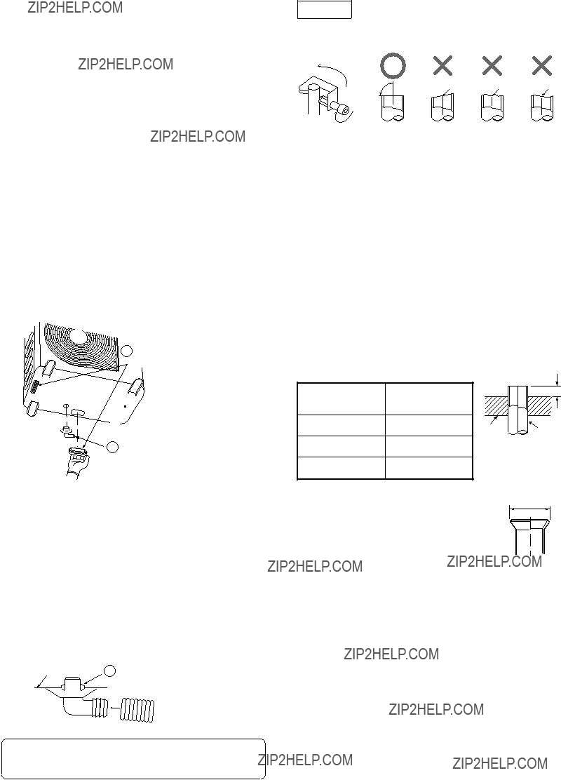
1.Flare processing procedures and precautions
a)Cutting the Pipe
By means of a pipe cutter, slowly cut the pipe so that it is not deformed.
b)Removing Burrs and Chips
If the flared section has chips or burrs, refrigerant leakage may occur. Carefully remove all burrs and clean the cut surface before installation.
c)Insertion of Flare Nut
??? 8 ???
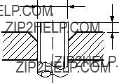
d) Flare Processing
Make certain that a clamp bar and copper pipe have been cleaned.
By means of the clamp bar, perform the flare processing correctly.
Use either a flare tool for R410A or conven- tional flare tool.
Flare processing dimensions differ according to the type of flare tool. When using a con- ventional flare tool, be sure to secure ???dimen- sion A??? by using a gauge for size adjustment.
??D
Fig.
Table
Table
??? 9 ???

Table
Fig.
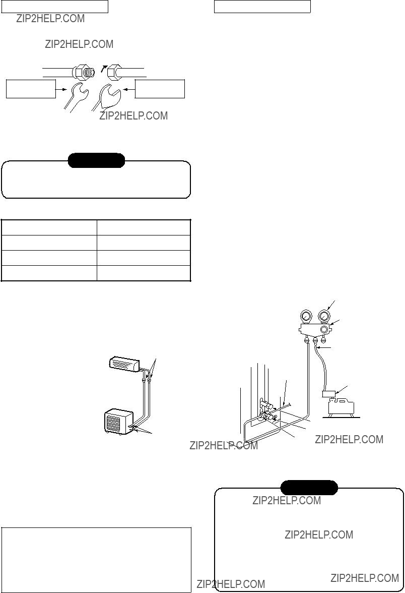
2.Flare Connecting Procedures and Precautions
a)Make sure that the flare and union portions do not have any scar or dust, etc.
b)Correctly align the processed flare surface with the union axis.
c)Tighten the flare with designated torque by means of a torque wrench. The tightening torque for R410A is the same as that for conventional R22. Incidentally, when the torque is weak, the gas leakage may occur.
When it is strong, the flare nut may crack and may be made
NOTE :
When applying oil to the flare surface, be sure to use oil designated by the manufacturer.
If any other oil is used, the lubricating oils may deteriorate and cause the compressor to burn out.
Table
??? 10 ???
The service port diameter of packed valve of the outdoor unit in the
The used refrigerating oil is changed, and mixing of oil may cause a trouble such as generation of sludge, clogging of capillary, etc. Accordingly, the tools to be used are classified into the following three types.
1.Tools exclusive for R410A (Those which cannot be used for conventional refrigerant (R22))
2.Tools exclusive for R410A, but can be also used for conventional refrigerant (R22)
3.Tools commonly used for R410A and for conventional refrigerant (R22)
The table below shows the tools exclusive for R410A and their interchangeability.
Tools exclusive for R410A (The following tools for R410A are required.)
Tools whose specifications are changed for R410A and their interchangeability
(Note 1) When flaring is carried out for R410A using the conventional flare tools, adjustment of projection margin is necessary. For this adjustment, a copper pipe gauge, etc. are necessary.
(Note 2) Charging cylinder for R410A is being currently developed.
General tools (Conventional tools can be used.)
In addition to the above exclusive tools, the following equipments which serve also for R22 are necessary as the general tools.
1.Vacuum pump
Use vacuum pump by attaching vacuum pump adapter.
2.Torque wrench (For ??6.35, ??9.52)
3.Pipe cutter
Also prepare the following equipments for other installation method and run check.
??? 11 ???
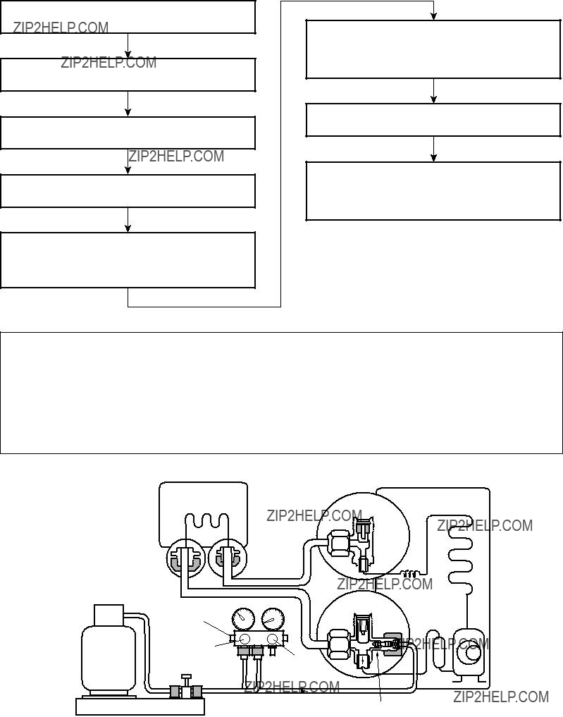
When it is necessary to recharge refrigerant, charge the specified amount of new refrigerant according to the following steps.
Recover the refrigerant, and check no refrigerant remains in the equipment.
Connect the charge hose to packed valve service port at the outdoor unit???s gas side.
Connect the charge hose to the vacuum pump adapter.
Open fully both packed valves at liquid and gas sides.
Place the handle of the gauge manifold Low in the fully opened position, and turn on the vacuum pump???s power switch. Then, evacuating the refrigerant in the cycle.
When the compound gauge???s pointer has indicated
Keep the status as it is for 1 to 2 minutes, and ensure that the compound gauge???s pointer does not return.
Set the refrigerant cylinder to the electronic balance, connect the connecting hose to the cylinder and the connecting port of the electronic balance, and charge liquid refrigerant.
(For refrigerant charging, see the figure below.)
1.Never charge refrigerant exceeding the specified amount.
2.If the specified amount of refrigerant cannot be charged, charge refrigerant bit by bit in COOL mode.
3.Do not carry out additional charging.
When additional charging is carried out if refrigerant leaks, the refrigerant composition changes in the refrigeration cycle, that is characteristics of the air conditioner changes, refrigerant exceeding the specified amount is charged, and working pressure in the refrigeration cycle becomes abnormally high pressure, and may cause a rupture or personal injury.
(Water heat
(Outdoor unit)
exchanger unit)
Fig.
??? 12 ???

1.Be sure to make setting so that liquid can be charged.
2.When using a cylinder equipped with a siphon, liquid can be charged without turning it upside down.
It is necessary for charging refrigerant under condition of liquid because R410A is mixed type of refrigerant. Accordingly, when charging refrigerant from the refrigerant cylinder to the equipment, charge it turning the cylinder upside down if cylinder is not equipped with siphon.
Refrigerant
cylinder
Electronic
balance
R410A refrigerant is HFC mixed refrigerant. Therefore, if it is charged with gas, the composi- tion of the charged refrigerant changes and the characteristics of the equipment varies.
cylinder Refrigerant
Electronic
balance
Siphon
Fig.
1.Silver brazing filler
Silver brazing filler is an alloy mainly composed of silver and copper. It is used to join iron, copper or copper alloy, and is relatively expensive though it excels in solderability.
2.Phosphor bronze brazing filler
Phosphor bronze brazing filler is generally used to join copper or copper alloy.
3.Low temperature brazing filler
Low temperature brazing filler is generally called solder, and is an alloy of tin and lead. Since it is weak in adhesive strength, do not use it for refrigerant pipes.
1.Phosphor bronze brazing filler tends to react with sulfur and produce a fragile compound water solution, which may cause a gas leakage. Therefore, use any other type of brazing filler at a hot spring resort, etc., and coat the surface with a paint.
2.When performing brazing again at time of servicing, use the same type of brazing filler.
1.Reason why flux is necessary
???By removing the oxide film and any foreign matter on the metal surface, it assists the flow of brazing filler.
???In the brazing process, it prevents the metal surface from being oxidized.
???By reducing the brazing filler???s surface tension, the brazing filler adheres better to the treated metal.
??? 13 ???

2.Characteristics required for flux
???Activated temperature of flux coincides with the brazing temperature.
???Due to a wide effective temperature range, flux is hard to carbonize.
???It is easy to remove slag after brazing.
???The corrosive action to the treated metal and brazing filler is minimum.
???It excels in coating performance and is harm- less to the human body.
As the flux works in a complicated manner as described above, it is necessary to select an adequate type of flux according to the type and shape of treated metal, type of brazing filler and brazing method, etc.
3.Types of flux
???Noncorrosive flux
Generally, it is a compound of borax and boric acid.
It is effective in case where the brazing tem- perature is higher than 800??C.
???Activated flux
Most of fluxes generally used for silver brazing are this type.
It features an increased oxide film removing capability due to the addition of compounds such as potassium fluoride, potassium chloride and sodium fluoride to the
4.Piping materials for brazing and used brazing filler/flux
1.Do not enter flux into the refrigeration cycle.
2.When chlorine contained in the flux remains within the pipe, the lubricating oil deteriorates. Therefore, use a flux which does not contain chlorine.
3.When adding water to the flux, use water which does not contain chlorine (e.g. distilled water or
4.Remove the flux after brazing.
As brazing work requires sophisticated techniques, experiences based upon a theoretical knowledge, it must be performed by a person qualified.
In order to prevent the oxide film from occurring in the pipe interior during brazing, it is effective to proceed with brazing while letting dry Nitrogen gas (N2) flow.
Never use gas other than Nitrogen gas.
1.Brazing method to prevent oxidation
1)Attach a reducing valve and a
2)Use a copper pipe to direct the piping mate- rial, and attach a
3)Apply a seal onto the clearance between the piping material and inserted copper pipe for Nitrogen in order to prevent backflow of the Nitrogen gas.
4)When the Nitrogen gas is flowing, be sure to keep the piping end open.
5)Adjust the flow rate of Nitrogen gas so that it is lower than 0.05 m3/Hr or 0.02 MPa (0.2kgf/cm2) by means of the reducing valve.
6)After performing the steps above, keep the Nitrogen gas flowing until the pipe cools down to a certain extent (temperature at which pipes are touchable with hands).
7)Remove the flux completely after brazing.
M Flow meter
Stop valve
Nitrogen gas cylinder
From Nitrogen cylinder
Pipe 

 Nitrogen gas
Rubber plug
Fig.
??? 14 ???
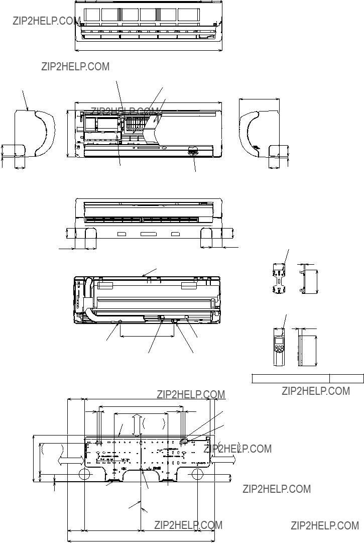
4. CONSTRUCTION VIEWS
7 60
Installation plate hanging section
Remote controller holder
64 5
125.5
Wireless remote controller
58 19
163
Parts name of remote controller
91
Minimum distance to wall
140 or more
3
91
??? 15 ???

A leg part
B leg part
60
(Pipe dia.
69.5147
Fan guard
Fin guard
When installing the outdoor unit, leave open in at least two of
directions (A), (B), (C) and (D)Z view shown in the figure below.
??? 16 ???
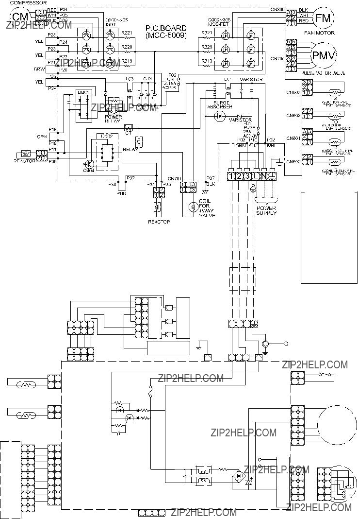
5. WIRING DIAGRAM
6. SPECIFICATIONS OF ELECTRICAL PARTS
??? 18 ???
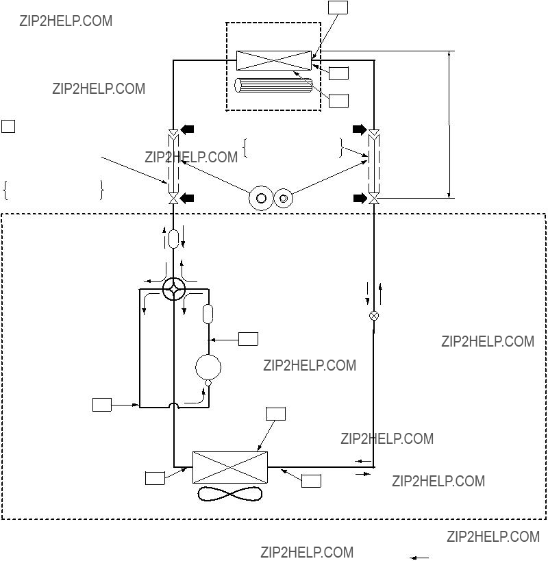
7. REFRIGERANT CYCLE DIAGRAM
P Pressure measurement
Gauge attaching port
Vacuum pump connecting port
Deoxidized copper pipe Outer dia. : 9.52mm Thickness : 0.8mm
Muffler
OUTDOOR UNIT
 Strainer
Pulse motor
valve at liquid side
 Strainer
Refrigerant amount : 0.82kg
NOTE :  Gas leak check position
 Refrigerant flow (Cooling) Refrigerant flow (Heating)
NOTE :
???The maximum pipe length of this air conditioner is 25 m. When the pipe length exceeds 15m, the additional charging of refrigerant, 20g per 1m for the part of pipe exceeded 15m is required. (Max. 200g)
???19 ???

NOTE :
???The maximum pipe length of this air conditioner is 25 m. When the pipe length exceeds 15m, the additional charging of refrigerant, 20g per 1m for the part of pipe exceeded 15m is required. (Max. 200g)
???20 ???
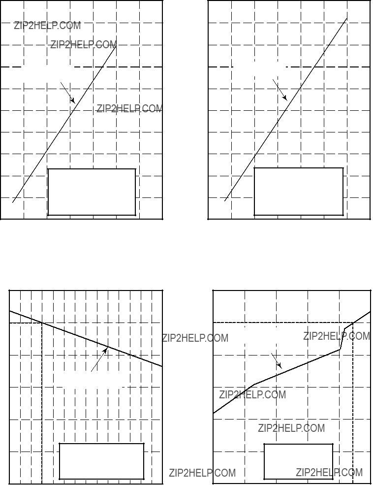
<Cooling>
<Heating>
NOTES :
1.Measure surface temperature of heat exchanger pipe around center of heat exchanger path U bent. (Thermistor themometer)
2.Connecting piping condition : 7.5 m
??? 21 ???
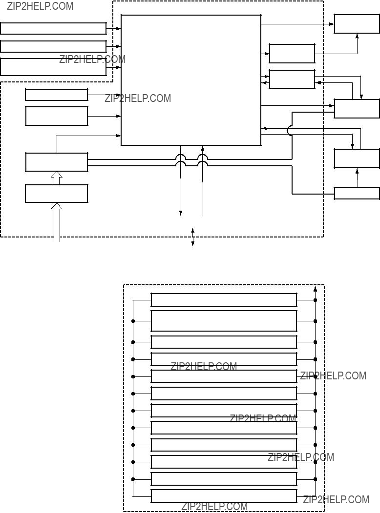
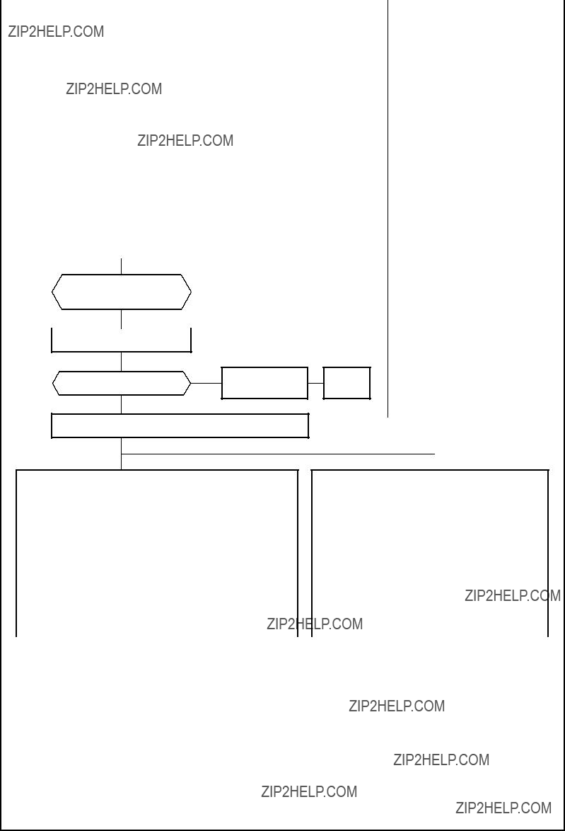
8. CONTROL BLOCK DIAGRAM
REMOTE CONTROLLER
Operation (START/STOP)
Operation Mode Selection
AUTO, COOL, DRY, HEAT
Thermo. Setting
Fan Speed Selection
ON TIMER Setting
OFF TIMER Setting
Louver AUTO Swing
Louver Direction Setting
ECO
Air Purifier
SLEEP
??? 22 ???
P.M.V. : Pulse Motor Valve
M.C.U. : Micro Control Unit

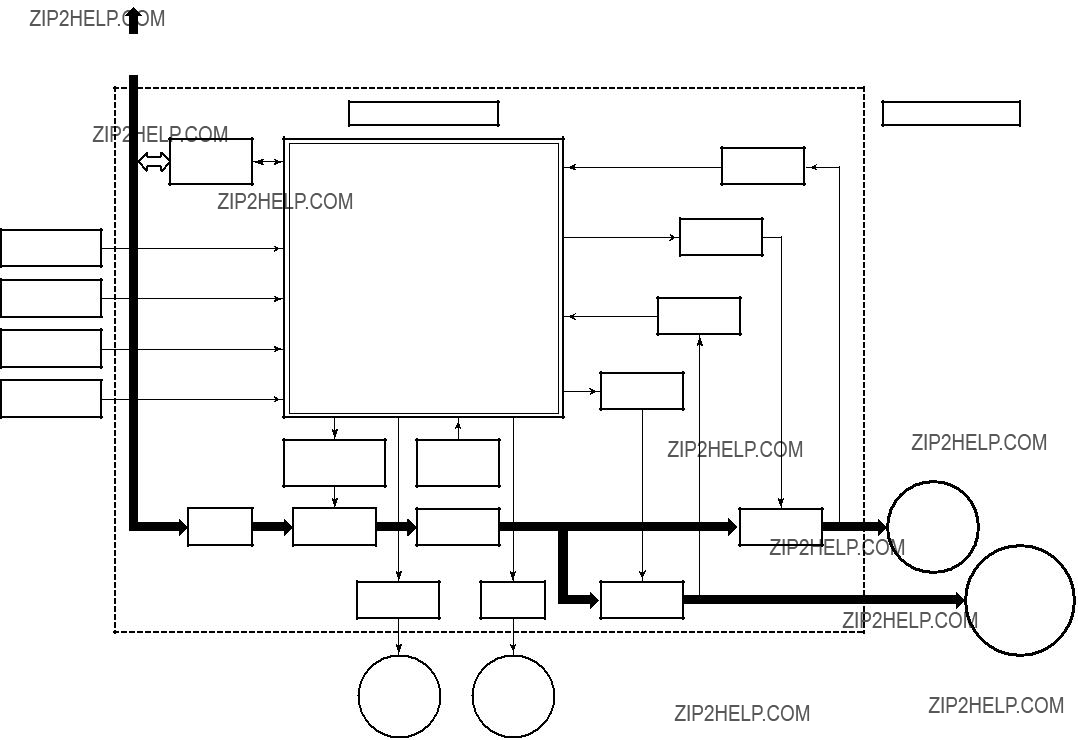
9. OPERATION DESCRIPTION
This air conditioner is a
The entire air conditioner is mainly controlled by the indoor unit controller.
The indoor unit controller drives the indoor fan motor based upon command sent from the remote controller, and transfers the operation command to the outdoor unit controller.
The outdoor unit controller receives operation com- mand from the indoor unit side, and controls the outdoor fan and the pulse motor valve. (P.M.V) Besides, detecting revolution position of the compres- sor motor, the outdoor unit controller controls speed of the compressor motor by controlling output voltage of the inverter and switching timing of the supply power (current transfer timing) so that motors drive according to the operation command.
And then, the outdoor unit controller transfers reversely the operating status information of the outdoor unit to control the indoor unit controller.
As the compressor adopts
1.Role of indoor unit controller
The indoor unit controller judges the operation commands from the remote controller and assumes the following functions.
???Judgment of suction air temperature of the indoor heat exchanger by using the indoor temp. sensor. (TA sensor)
???Judgment of the indoor heat exchanger tempera- ture by using heat exchanger sensor (TC sensor)
???Louver motor control
???Indoor fan motor operation control
???LED (Light Emitting Diode) display control
???Transferring of operation command signal (Serial signal) to the outdoor unit
???Reception of information of operation status (Serial signal including outside temp. data) to the outdoor unit and judgment/display of error
???Air purifier operation control
2.Role of outdoor unit controller
Receiving the operation command signal (Serial signal) from the indoor unit controller, the outdoor unit performs its role.
???Detection of inverter input current and current release operation
???
???Compressor and outdoor fan stop function when serial signal is off (when the serial signal does not reach the board assembly of outdoor control by trouble of the signal system)
???Transferring of operation information (Serial signal) from outdoor unit controller to indoor unit controller
???Detection of outdoor temperature and operation revolution control
???Defrost control in heating operation (Temp. measurement by outdoor heat exchanger and control for
3.Contents of operation command signal (Serial signal) from indoor unit controller to outdoor unit controller
The following three types of signals are sent from the indoor unit controller.
???Operation mode set on the remote controller
???Compressor revolution command signal defined by indoor temperature and set temperature (Correction along with variation of room tempera- ture and correction of indoor heat exchanger temperature are added.)
???Temperature of indoor heat exchanger
???For these signals ([Operation mode] and [Com- pressor revolution] indoor heat exchanger tem- perature), the outdoor unit controller monitors the input current to the inverter, and performs the followed operation within the range that current does not exceed the allowable value.
4.Contents of operation command signal (Serial signal) from outdoor unit controller to indoor unit controller
The following signals are sent from the outdoor unit controller.
???The current operation mode
???The current compressor revolution
???Outdoor temperature
???Existence of protective circuit operation
For transferring of these signals, the indoor unit controller monitors the contents of signals, and judges existence of trouble occurrence.
Contents of judgment are described below.
???Whether distinction of the current operation status meets to the operation command signal
???Whether protective circuit operates
When no signal is received from the outdoor unit controller, it is assumed as a trouble.
???Compressor operation control
???Operation control of outdoor fan motor
???P.M.V. control
???
??? 24 ???
??? 25 ???

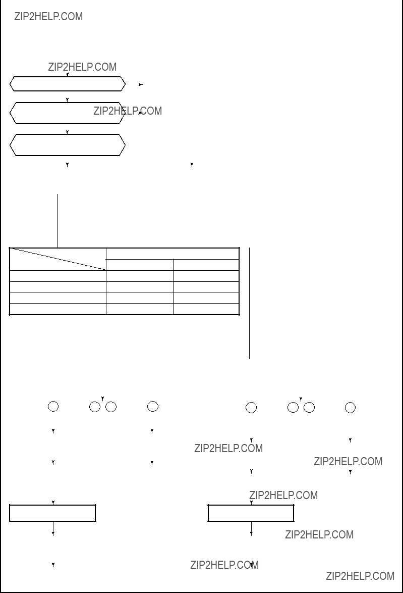
1. Basic 1. Operation control
operation
Receiving the user???s operation condition setup, the operation statuses of indoor/outdoor units are controlled.
1)The operation conditions are selected by the remote controller as shown in the below.
2)A signal is sent by ON button of the remote controller.
3)The signal is received by a sensor of the indoor unit and processed by the indoor controllers as shown in the below.
4)The indoor controller controls the indoor fan motor and louver motor.
5)The indoor controller sends the operation command to the outdoor controller, and sends/receives the control status with a serial signal.
6)The outdoor controller controls the operation as shown in the left, and also controls the compres- sor, outdoor fan motor,
Remote controller
Selection of operation conditions
ON/OFF
Control contents of remote controller
???ON/OFF (Air conditioner/Air purifier)
???Operation select (COOL/HEAT/AUTO/DRY)
???Temperature setup
???Air direction
???Swing
???Air volume select (AUTO/LOW/LOW+/MED/MED+/HIGH)
???ECO
???ON timer setup
???OFF timer setup
???High power
Indoor unit
Signal receiving
Indoor unit control
Operation command
Serial signal send/receive
Indoor unit control
???Command signal generating function of indoor unit operation
???Calculation function (temperature calculation)
???Activation compensation function of indoor fan
???Cold draft preventive function
???Timer function
???Indoor heat exchanger release control
???Indoor fan motor
???Louver motor
??? 26 ???
1.Basic 2. Cooling/Heating operation
operation
The operations are performed in the following parts by controls according to cooling/heating conditions.
1)Receiving the operation ON signal of the remote controller, the cooling or heating operation signal starts being transferred form the indoor controller to the outdoor unit.
2)At the indoor unit side, the indoor fan is operated according to the contents of ???2. Indoor fan motor control??? and the louver according to the contents of ???9. Louver control???, respectively.
3)The outdoor unit controls the outdoor fan motor, compressor, pulse motor valve and
*1. The power coupler of
??? 27 ???

??? 28 ???

??? 29 ???
4) Motor operates as shown in the table below.
In cooling operation
In Heating operation
Outdoor fan speed (rpm)
??? 30 ???
??? 31 ???

Item
6.Release protective control by tempera- ture of indoor heat exchanger
??? 32 ???

When indoor temperature is low, this function stores the heat by heating winding depended on the outdoor temperature and then it enables the hot air blowing out quickly.
In case of operation stop
Start of heating operation
*The minimum value of Te sensor 10 to 15 minutes after start of operation is stored in memory as Te0.
Description
When the following conditions are satisfied, winding is heated by output varied by the outdoor heat exchanger temperature.
Condition 1 :
The previous operation was heating.
Condition 2 :
2 hours passed after operation stop.
Condition 3 :
The room temperature is 20??C or lower.
The indoor temperature sensor detects the room temperature.
If the detected room temperature is 20??C or lower, the outdoor heat exchanger temperature sensor detects the outdoor heat exchanger temperature. As shown in the left figure, winding of the compressor is heated for each division of the tempera- ture ( for each outdoor temperature) and the heat is stored.
The necessity of defrost operation is detected by the outdoor heat exchanger temperature. The conditions to detect the necessity of defrost operation differ in A, B, or C zone each. (Table 1)
<Defrost operation>
??? Defrost operation in A to C zones
1)Stop operation of the compressor for 20 seconds.
2)Invert (ON)
3)The outdoor fan stops at the same time when the compressor stops.
4)When temperature of the indoor heat exchanger becomes 38??C or lower, stop the indoor fan.
<Finish of defrost operation>
???Returning conditions from defrost operation to heating operation
1)Temperature of outdoor heat exchanger rises to +8??C or higher.
2)Temperature of outdoor heat exchanger is kept at +5??C or higher for 80 seconds.
3)Defrost operation continues for 15 minutes.
<Returning from defrost operation>
1)Stop operation of the compressor for approx. 50 seconds.
2)Invert (OFF)
3)The outdoor fan starts rotating at the same time when the compressor starts.
??? 33 ???
Item
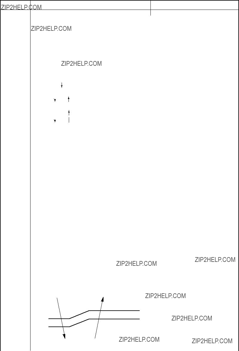
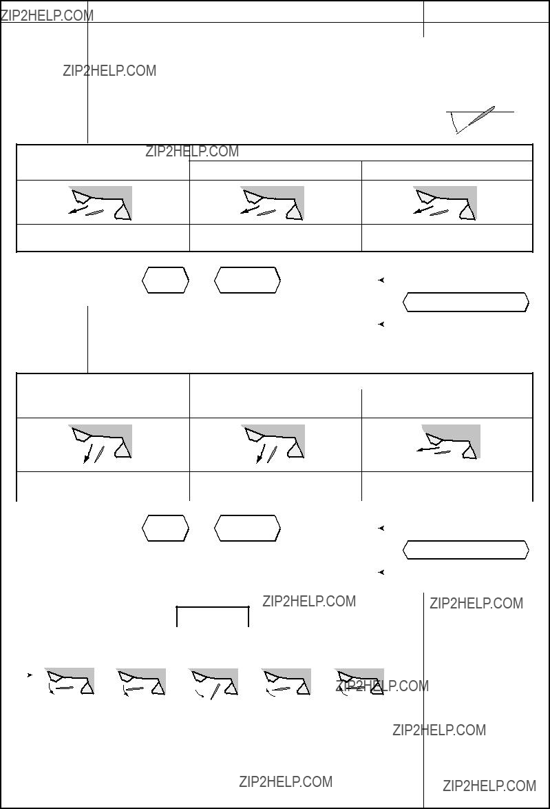
9.Louver control
1)Louver position
This function controls the air direction of the indoor unit.
???The position is automatically controlled according to the operation mode (COOL/HEAT).
???The set louver position is stored in memory by the microcomputer, and the louver returns to the stored position when the next operation is performed. (Cooling/heating memory position)
The angle of the louver is indicated as the horizontal angle is 0??.
When the louver closes fully, it directs approx. 49?? upward.
Powerful
Room temp. (Ta) < Set temp. (Tsc) + 3.5 Room temp. (Ta) ??? Set temp. (Tsc) + 3.5
Initial setting of ???Cooling storage position??? Louver : Directs downward (9??)
2) Louver position in heating operation
???The louver position can be arbitrarily set up by pressing [FIX] button.
???Swing
When pressing [SWING] button during operation, the louver starts swinging.
??? 34 ???

??? 35 ???
Fan ON
Air
??? 36 ???

??? 37 ???

PMV open degree control
*SH (Super Heat amount) =
Ts (Temperature of suction pipe of the compressor) ???
Tc or Te (Heat exchanger temperature at evaporation side)
*PMV: Pulse Motor Valve
??? 38 ???

???To stop an ongoing clean operation at any time
Press the start/stop button on the remote controller twice during the clean operation. (After pressing the button for the first time, press it for the second time without delay (within 10 minutes).)
??? 39 ???

16.Clean operation Setting the clean operation release release
The indoor unit???s buzzer emits three beeps, and the OPERATION indicator flashes at 5 Hz intervals.
This completes the clean operation release setting.
Setting the clean operation
Cut J04 of the indoor P.C. board
*This step may be skipped if the auto restart function is not required.
Hold down the auto operation switch on the indoor unit for at least 3 seconds but not more than 10 seconds.
The indoor unit???s buzzer emits three beeps, and the OPERATION indicator flashes at 5 Hz intervals.
This completes the clean operation setting.
Indoor P.C. board
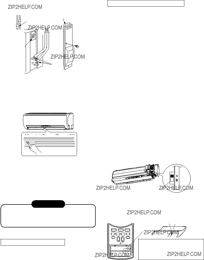
Setting the remote controller
Switching between A and B is enabled by cutting the jumper wire inside the battery box using pliers.
1)Slide open the remote controller cover and remove the batteries.
* Even after the jumper wire has been cut, switching between A and B is still possible by pressing the CHECK button and FIX button together.
The A or B setting, which was switched by pressing the CHECK button and FIX button together, is restored to the setting established prior to the switching when the battery is replaced or the RESET button is pressed.
Position of remote controller selector switch
When switching between settings ???A??? and ???B???, always switch the indoor unit board and the remote controller as a pair. (Otherwise, the indoor unit will not accept the remote controller???s signals.)
Selector switch
??? 41 ???

This indoor unit is equipped with an automatic restarting function which allows the unit to restart operating with the set operating conditions in the event of a power supply being accidentally shut down.
The operation will resume without warning three minutes after power is restored.
This function is not set to work when shipped from the factory. Therefore it is necessary to set it to work.
To set the auto restart function, proceed as follows:
The power supply to the unit must be on ; the function will not set if the power is off.
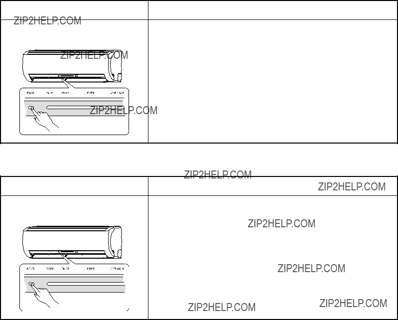
Press the [RESET] button located in the center of the front panel continuously for three seconds.
The unit receives the signal and beeps three times.
The unit then restarts operating automatically in the event of power supply being accidentally shut down.
??? When the unit is standby (Not operating)
??? When the unit is in operation
???When the unit is turned on by this function, the louver will not swing even though it was swinging automatically before shutting down.
???While the filter check indicator is on, the RESET button has the function of filter reset button.
??? 42 ???
To cancel auto restart function, proceed as follows :
Repeat the setting procedure : the unit receives the signal and beeps three times.
The unit will be required to be turned on with the remote controller after the main power supply is turned off.
??? When the system is on
??? When the system is operating
When the unit is turned off because of power failure during timer operation, the timer operation is can- celled. In that case, set the timer operation again.
NOTE :
The Everyday Timer is reset while a command signal can be received from the remote controller even if it stopped due to a power failure.
When the elapsed time reaches 1000 hours after air purifier operation, the FILTER indicator lights.
After cleaning the filters, turn off the FILTER indicator.
Press [RESET] button on the indoor unit.
NOTE :
If [RESET] button is pushed while the FILTER indica- tor is not lit, the indoor unit will start the automatic operation.
When you want a temporary operation while the FILTER lamp lights, press [RESET] button to turn off the FILTER lamp. (See page 36)
??? 43 ???
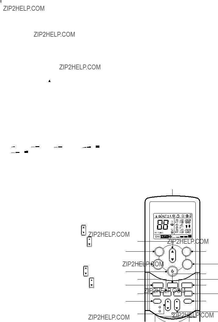
1 Infrared signal emitter
Transmits signal to the indoor unit.
2  button
Press the button to start operation. (A receiving beep is heard.)
Press the button again to stop operation. (A receiving beep is heard.)
If no receiving sound is heard from the indoor unit, press the button twice.
3 Mode select button (MODE)
Press this button to select a mode.
Each time you press the button, the modes cycle in order from A : Auto changeover control,
 : Cool,
  : Dry,
  : Heat and back to A. (A receiving beep is heard.)
4 Temperature button ( TEMP )
 .. The temperature setting is increased to 30??C.
 .. The temperature setting is reduced to 17??C. (A receiving beep is heard.)
5 Fan speed button (FAN)
Press this button to select the fan speed.
When you select AUTO, the fan speed is automati- cally adjusted according to the room temperature.
You can also manually select the desired fan speed
6 Auto louver button (SWING)
Press this button to swing the louver. (A receiving beep is heard.)
Press this button again to stop the louver from swinging. (A receiving beep is heard.)
7 Set louver button (FIX)
Press this button again to adjust the air flow direction. (A receiving beep is heard.)
8 ON timer button (ON)
Use this button to change the clock and ON timer times.
To move up the time, press  of the ???ON ON ??? button.
To move down the time, press  of the ???ON ON ??? button.
9 OFF timer button (OFF)
Use this button to change the OFF timer times.
To move up the time, press  of the ???OFF OFF ??? button.
To move down the time, press  of the ???OFF OFF ??? button.
10 Reserve button (SET)
Press this button to store the time settings. (A receiving beep is heard.)
11 Cancel button (CLR)
Press this button to cancel the ON timer and OFF timer. (A receiving beep is heard.)
12 High power button (Hi POWER)
Press this button to start high power operation.
13 Memory button (MEMO)
Press this button to ready for storing the settings. Hold down the button for more than 3 seconds to store the setting indicated on the remote controller and until the  mark is displayed.
14 Automatic operation button (AUTO)
Press this button to operate the air conditioner automatically. (A receiving beep is heard.)
15 Economy button (ECO)
Press this button to operate the air conditioner economically.
16 PRESET button
Press this button to operate the air conditioner to the settings stored using the MEMO button.
17 PURE button (PURE)
Press this button to start the electrical air purifying operation.
Press the button again to stop operation.
18 Sleep time button (SLEEP)
Press this button to start the sleep timer (OFF timer) operation.
You can select the OFF timer time from among four settings (1, 3, 5 or 9 hours).
1
??? 44 ???

[Display]
All indications, except for the clock time indicator, are displayed by pressing the  button.
This transmission mark  indicates when the remote controller transmits signals to the indoor unit.
2 Mode indicator
Indicates the current operation mode.
(AUTO : Automatic control, A : Auto changeover
control,  : Cool,
 : Dry,
  : Heat)
3 Temperature indicator
Indicates the temperature setting. (17??C to 30??C)
4 PURE indicator
Shows that the electrical air purifying operation is in progress.
5 FAN speed indicator
Indicates the selected fan speed.
AUTO or five fan speed levels
(LOW , LOW+
  , MED
, MED  , MED+
  ,
,
Indicates AUTO when the operating mode is either AUTO or  : Dry.
The time setting for timer operation or the clock time is indicated.
The current time is always indicated except during TIMER operation.
7
Indicates when the
Press the
8  (MEMORY) indicator
Flashes for 3 seconds when the MEMO button is pressed during operation.
The mark is shown when holding down the button for more than 3 seconds while the mark is flashing.
Press another button to turn off the mark.
9 ECO indicator
Indicates when the ECO is in activated.
Press the ECO button to start and press it again to stop operation.
10 A, B change indicator remote controller
When the remote controller switching function is set, ???B??? appears in the remote controller display. (When the remote controller setting is ???A???, there is no indication at this position.)
O 


During operation, only the relevant indicators are shown on the remote controller.
??? 45 ???
When
1.Automatic operation
???The indoor unit operates in according to the current operation.
2.Cooling operation
???The preset temperature drops 1??C.
(The value of the preset temperature on the remote controller does not change.)
???If the difference between the preset temperature and the room temperature is big, the horizontal louver moves to the
Then when the difference between them gets smaller, the horizontal louver returns automatically.
3.Heating operation
???The preset temperature increases 2??C.
(The value of the preset temperature on the remote controller does not change.)
4.The
??? 46 ???

10. INSTALLATION PROCEDURE
For the rear left and left piping
1 Installation plate
Hook
140 mm or more
74 mm or more
Hook
Wall
Insert the cushion between the indoor unit and wall, and tilt the indoor unit for better installation work.
7 Mounting screw
Do not allow the drain hose to become slack.
Cut the piping hole slightly sloped
5
4 Remote controller holder (Mounting holes on both left and right sides)
200 mm or more
(B)
As shown in the figure, position power cord and connecting cable downward, and lead out along piping connection port.
8 Remote controller holder mounting screw
When installing the outdoor unit, leave open in at least two of directions (A), (B), (C) and (D) shown in the right figure.
Ensure sufficient space to allow drainage
(A)
250 mm or more from wall
Power cord
Extension drain hose (Option:
Insulate the refrigerant pipes separately, not together.
6 mm thick heat resisting polyethylene foam
Before installing the wireless remote controller
???With the remote controller cover removed, correctly load the supplied batteries while observing their polarity.
Cover
3 Batteries
2 Wireless remote controller
??? 47 ???

Attachment bolt arrangement of outdoor unit
???Secure the outdoor unit with the attachment bolts and nuts if the unit is likely to be exposed to a strong wind.
???Use ??8 mm or ??10 mm anchor bolts and nuts.
If it is necessary to drain the defrost water, attach drain nipple to the base plate of the outdoor unit before installing it.
Elongated
Drain hole
Diffuser ( ??? )
??? 48 ???

Changes in the product and components
In the case of an air conditioner using R410A, in order to prevent any other refrigerant from being charged accidentally, the service port diameter of the outdoor unit control valve (3 way valve) has been changed. (1/2 UNF 20 threads per inch)
???In order to increase the pressure resisting strength of the refrigerant piping flare processing diameter and size of opposite side of flare nuts has been changed. (for copper pipes with nominal dimensions 1/2 and 5/8)
New tools for R410A
???Incidentally, the ???refrigerant cylinder??? comes with the refrigerant designation (R410A) and protector coating in the U. S???s ARI specified rose color (ARI color code: PMS 507).
???Also, the ???charge port and packing for refrigerant cylinder??? require 1/2 UNF 20 threads per inch corresponding to the charge hose???s port size.
??? 49 ???

???A place which provides enough spaces around the indoor unit as shown in the diagram.
???A place where there are no obstacle near the air inlet and outlet.
???A place which allows easy installation of the piping to the outdoor unit.
???A place which allows the front panel to be opened.
???The indoor unit shall be installed so that the top of the indoor unit is positioned at least 2m in height.
???Also, avoid putting anything on the top of the indoor unit.
CAUTION
???Direct sunlight on the indoor unit wireless receiver should be avoided.
???The microprocessor in the indoor unit should not be too close to
(For details, see the owner's manual.)
Remote controller
???Should be placed where there are no obstacles, such as curtains, that may block the signal.
???Do not install the remote controller in a place exposed to direct sunlight or close to a heating source, such as a stove.
???Keep the remote controller at least 1 m away from the nearest TV set or stereo equipment.
(This is necessary to prevent image disturbances or noise interference.)
???The location of the remote controller should be determined as shown below.
*: Axial distance
lation Plate
Drilling a hole
When install the refrigerant pipes from the rear.
Fig.
1.After determining the pipe hole position on the
installation plate ( ??) drill the pipe hole (??65 mm) at a slight downward slant to the outdoor side.
NOTE :
???When drilling into a wall that contains a metal lath, wire lath or metal plate, be sure to use a pipe hole brim ring sold separately.
Mounting the installation plate
Anchor bolt holes
Pipe hole 


??? 50 ???
When the installation plate is directly mounted on the wall
1.Securely fit the installation plate onto the wall by screws with the upper and lower catches, that hold the indoor unit, facing out.
2.To mount the installation plate on a concrete wall use anchor bolts. Drill the anchor bolt holes as illustrated in the above figure.
3.Install the installation plate horizontally and level.
CAUTION
When installing the installation plate with mount- ing screw, do not use the anchor bolt hole. Otherwise the unit may fall down and result in personal injury and property damage.
Anchor bolt
Projection 15mm or less
1.The supply voltage must be the same as the rated voltage of the air conditioner.
2.Prepare a power source for the exclusive use of the air conditioner.
NOTE :
???Wire type :
More than
CAUTION
???This appliance can be connected to a main circuit breaker in either of the following two ways.
1.Connection to fixed wiring:
A switch or circuit breaker which discon- nects all poles and has a contact separa- tion of at least 3 mm must be incorporated in the fixed wiring. An approved circuit breaker or switch must be used.
2.Connection with power supply plug:
Attach power supply plug with power cord and plug it into wall outlet. An approved power supply cord and plug must be used.
Fig.
5 mm dia. hole
 7 Mounting screw ??4 ?? 25L
 Clip anchor (local parts)
Fig.
CAUTION
Failure to securely install the unit may result in personal injury and/or property damage if the unit falls.
???In case of block, brick, concrete or similar type walls, drill 5 mm dia. holes in the wall.
???Insert clip anchors for the ??? mounting screws.
NOTE :
???Install the installation plate using mounting screws between 4 to 6, being sure to secure all four corners.
NOTE :
???Perform wiring work being sure the wire length is long enough.
How to connect the connecting cable
Wiring the connecting cable can be carried out without removing the front panel.
1.Remove the air inlet grille. Open the air inlet grille upward and pull it toward you.
2.Remove the terminal cover and cord clamp.
3.Insert the connecting cable (or as according to local regulations/codes) into the pipe hole on the wall.
4.Pull the connecting cable through the cable slot on the rear panel so that it protrudes about
15 cm out of the front.
5.Insert the connecting cable fully into the terminal block and secure it tightly with screws.
6.Tightening torque: 1.2 N???m (0.12 kgf???m)
7.Secure the connecting cable with the cord clamp.
8.Attach the terminal cover, rear plate bushing and air inlet grille on the indoor unit.
??? 51 ???
CAUTION
???Be sure to refer to the wiring system diagram labeled inside the front panel.
???Check local electrical regulations for any specific wiring instructions or limitations.
Terminal cover
Screw
Piping and drain hose forming
???Since condensation results in machine trouble, make sure to insulate both the connecting pipes separately.
(Use polyethylene foam as insulating material.)
Rear right
Screw
Rear left
Bottom left
Left
Bottom right
Right
Connecting cable
Fig.
Terminal block
Fig.
Connecting cable
About 15 cm
Fig.
70 mm
10 mm
50 mm
Fig.
NOTE :
WIRE TYPE : more than H07
Fig.
1.
Cut out the slit on the left or right side of the front panel for the left or right connection and the slit on the bottom left or side of thefront panel for the bottom left or right connection with a pair of nippers.
2.Changing drain hose
For left connection,
How to remove the drain cap
Clip drain cap with
Fig.
How to remove the drain hose
The drain hose is secured in place by a screw.
Remove the screw securing the drain hose, then pull out the drain hose.
Fig.
??? 52 ???

How to attach the drain cap
1. Insert hexagonal wrench (4 mm).
4 mm
Fig.
2. Firmly insert drain cap.
No gap
Do not apply lubricating oil (refrigerant machine oil) when inserting the drain cap. If applied, deterioration and
drain leakage of the drain Insert a hexagon plug may occur.
wrench (??4mm)
Fig.
How to attach the drain hose
Always use the original screw that secured the drain hose to the unit. If using a different screw may cause water to leak.
Insert the drain hose firmly until the connector
In case of bottom right or bottom left piping
???After making slits on the front panel with a knife or similar tool, cut them out with a pair of nippers or an equivalent tool.
Slit
Fig.
Bend the connecting pipes so that they are posi- tioned within 43 mm above the wall surface.
If the connecting pipes are positioned more than 43 mm above the wall surface, the indoor unit may be unstable.
When bending the connecting pipe, make sure to use a spring bender to avoid crushing the pipe.
Refer to the table below for the bending radius of each connection pipe.
To connect the pipe after installation of the unit (figure)
contacts with the insulation, then secure it in place using the original screw.
220 mm
(To the front flare)
Gas side
CAUTION
Securely insert the drain hose and drain cap; otherwise, water may leak.
In case of right or left piping
???After making slits on the front panel with a knife or similar tool, cut them out with a pair of nippers or an equivalent tool.
170 mm 
Liquid side
R30 or less (??6.35), R40 or less (??9. 52), R50 or less (??12. 7) Use polishing (polyethylene core or the like for bending pipe).
Use a screwdriver handle, etc.
Fig.
Slit
Fig.
NOTE :
If the pipe is incorrectly bent, the indoor unit may be unstable on the wall.
After passing the connecting pipe through the pipe hole, connect the connecting pipe to the auxiliary pipes and wrap the facing tape around them.
??? 53 ???

CAUTION
???Bind the auxiliary pipes (two) and connecting cable with facing tape tightly.
In case of leftward piping and
 Indoor unit
1. Run the drain hose at a downward sloped angle.
NOTE :
???Hole should be made at a slight downward slant on the outdoor side.
Auxiliary pipes 
Installation plate
Connecting cable
50 mm or more
Fig.
???Carefully arrange the pipes so that none of the pipes stick out of the rear plate of the indoor unit.
???Carefully connect the auxiliary pipes and connecting pipes to each other and cut off the insulating tape wound on the connecting pipe to avoid
???Since condensation can result in machine performance trouble, be sure to insulate both connecting pipes. (Use polyethylene foam as insulating material.)
???When bending a pipe, be careful not to crush it.
1.Pass the pipe through the hole in the wall, and hook the indoor unit on the installation plate at the upper hooks.
2.Swing the indoor unit to right and left to confirm that it is firmly hooked on the installation plate.
3.While pressing the indoor unit onto the wall, hook it at the lower part on the installation plate.
Pull the indoor unit toward you to confirm that it is firmly hooked on the installation plate.
1 Hook here
 1 Installation plate
Fig.
???For detaching the indoor unit from the installation plate pull the indoor unit toward you while pushing the bottom up at the specified places.
Fig.
2.Put water in the drain pan and make sure that the water is being drained outside.
3.When connecting extension drain hose, insulate the connection part of extension drain hose with shield pipe.
Shield pipe
Fig.
CAUTION
Install the drain pipe for proper drainage.
Improper drainage can result in water dripping inside the room.
This air conditioner has been designed to drain water collected from condensation which forms on the back of the indoor unit, to the drain pan.
Therefore, do not locate the power cord and other parts at a high place than the drain guide.
Wall
Drain guide
Space for pipes
Push
Push
Fig.
Fig.
??? 54 ???
???A place which provides enough space around the outdoor unit as shown in the diagram.
???A place which can bear the weight of the outdoor unit and does not allow an increase in noise level and vibration.
???A place where the operation noise and discharged air do not disturb neighbors.
???A place which is not exposed to a strong wind.
???A place free of combustible gases.
???A place which does not block a passageway.
???When the outdoor unit is to be installed in an elevated position, be sure to secure its feet.
???This air conditioner accepts a connection piping length of up to 25 m.
???There is no need to add refrigerant as long as the length of the connection piping is 15 m or less.
???You will need to add 20 g of refrigerant per meter of added connection piping for installations requiring connection piping to be between 16 m to 25 m.
???An allowable height level is up to 10 m.
???A place where the drain water does not cause any problems.
Precautions for adding refrigerant
???Use a scale having a precision with at least 10 g per index line when adding the refrigerant.
Do not use a bathroom scale or similar instrument.
???Use liquid refrigerant when refilling the refrigerant. Since the refrigerant is in liquid form, it can fill quickly.
Therefore, perform the filling operation carefully and insert the refrigerant gradually.
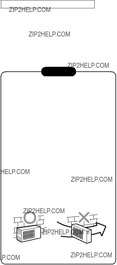
CAUTION
1.Install the outdoor unit without anything blocking the discharging air.
2.When the outdoor unit is installed in a place always exposed to strong winds like on the coast or on a high story of a building, secure the normal fan operation using a duct or a wind shield.
3.Especially in windy areas, install the unit to prevent the admission of wind.
4.Installation in the following places may result in trouble.
Do not install the unit in such places.
???A place full of machine oil.
???A
???A place full of sulfide gas.
???A place where
Strong
wind
Fig.
??? 55 ???
???Holes are provided on the base plate of the outdoor unit to ensure that the defrost water produced during heating operations is drained off efficiently.
If a centralized drain is required when installing the unit on a balcony or wall, follow the steps below to drain off the water.
1.Proceed with
1)Place four fingers into each cap, and insert the caps into the water drain holes by pushing them into place from the underside of the base plate.
2)Press down on the outer circumferences of the caps to ensure that they have been inserted tightly.
(Water leaks may result if the caps have not been inserted properly, if their outer circumfer- ences lift up or the caps catch on or wedge against something.)
10

 Base plate
9 Drain nipple
Flaring
1. Cut the pipe with a pipe cutter.
Fig.
2. Insert a flare nut into the pipe, and flare the pipe.
??? Projection margin in flaring : A (Unit : mm)
Rigid (Clutch type)
Imperial (Wing nut type)
Fig.
12.72.0 to 2.5
??? Flaring size : B (Unit : mm)
B
2.Install the drain nipple ??? and a commercially available drain hose (with 16 mm inside diam- eter), and drain off the water.
(For the position where the drain nipple ??? is installed, refer to the installation diagram of the indoor and outdoor units.)
???Check that the outdoor unit is horizontal, and route the drain hose at a downward sloped angle while ensuring that it is connected tautly.
Commercially available
 drain hose
Do not use ordinary garden hose, but one can flatten and prevent water from draining.
Fig.
Fig.
???In case of flaring for R410A with the conventional flare tool, pull it out approx. 0.5 mm more than that of R22 to adjust to the specified flare size.
The copper pipe gauge is useful for adjusting projection margin size.
??? 56 ???
Tightening Connection
Align the centers of the connecting pipes and tighten the flare nut as much as possible with your fingers. Then tighten the nut with a wrench and torque wrench as shown in the figure.
???Do not apply excessive force. Otherwise, the nut may break.
(Unit : N??m)
Use a vacuum pump
Be sure to use a vacuum pump with
1.Connect the charge hose from the manifold valve to the service port of the gas side packed valve.
2.Connect the charge hose to the port of the vacuum pump.
3.Open fully the low pressure side handle of the gauge manifold valve.
4.Operate the vacuum pump to begin evacuating. Perform evacuating for about 15 minutes if the piping length is 20 meters (15 minutes for 20 meters) (assuming a pump capacity of 27 liters per minute).
Confirm that the compound pressure gauge reading is
5.Close the low pressure valve handle of gauge manifold.
6.Open fully the valve stem of the packed valves (both sides of Gas and Liquid).
7.Remove the charging hose from the service port.
8.Securely tighten the caps on the packed valves.
Compound Pressure gauge pressure
gauge 


Handle Lo 

Charge hose  (For R410A only)
Connecting pipe
Manifold valve
 Handle Hi
(Keep full closed)
Charge hose (For R410A only)
Vacuum pump adapter for
(For R410A only)
Vacuum
pump
Packed valve at liquid side Packed valve at gas side
Service port
(Valve core (Setting pin))
Fig.
CAUTION
???IMPORTANT POINTS FOR PIPING WORK
1.Keep dust and moisture from entering the pipes.
2.Tighten connections carefully (between pipes and unit).
3.Evacuate the air in the connecting pipes using a VACUUM PUMP.
4.Check for gas leaks at all connections.
??? 57 ???
Packed Valve handling precautions
???Open the valve stem all the way; but do not try to open it beyond the stopper.
???Securely tighten the valve stem cap with torque in the following table:
Gas side (?? 12.7 mm) 50 to 62 N???m (5.0 to 6.2 kgf???m)
Gas side (?? 9.52 mm) 33 to 42 N???m (3.3 to 4.2 kgf???m)
Liquid side (??6.35 mm) 14 to 18 N???m (1.4 to 1.8 kgf???m)
Hexagonal wrench is required.
Fig.
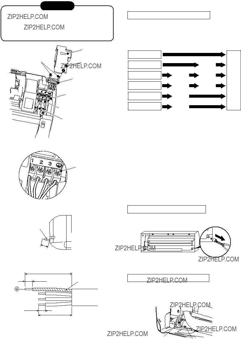
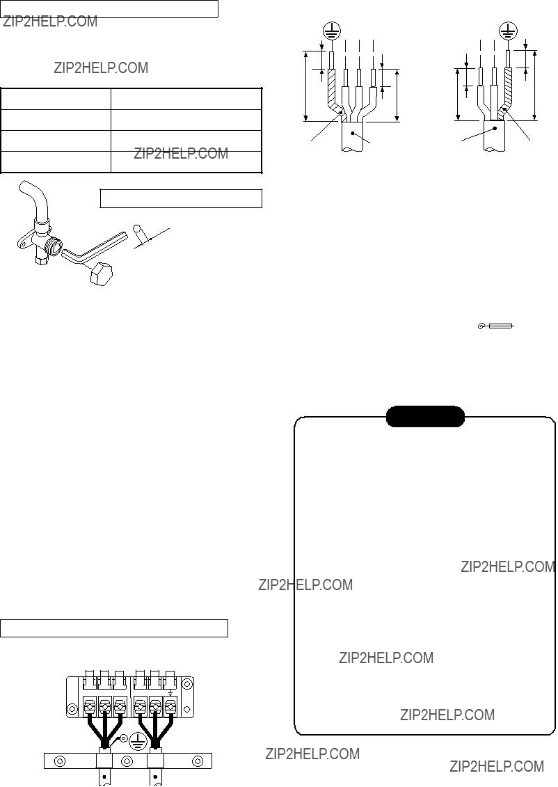
1.Remove the valve cover, the electric parts cover and the cord clamp from the outdoor unit.
2.Connect the connecting cable to the terminal as identified by the matching numbers on the terminal block of indoor and outdoor unit.
3.Insert the power cord and the connecting cable fully into the terminal block and secure it tightly with screws.
4.Insulate the unused cords (conductors) from water entering in the outdoor unit. Locate them so that they do not touch any electrical or metal parts.
5.Secure the power cord and the connecting cable with the cord clamp.
6.Attach the electric parts cover and the valve cover on the outdoor unit.
Stripping length of connecting cable
Terminal block
Connecting cable  Power cord
Fig.
Fig.
CAUTION
???Incorrect wiring connection may cause electri- cal parts to burn out.
???Be sure to comply with local regulations/codes when running the wire from outdoor unit to indoor unit.
(Size of wire and wiring method etc.)
???Every wire must be securely connected.
???This installation fuse (25A D type  ) must be used for the power supply line.
???If incorrect or incomplete wiring is carried out, fire or smoke may result.
???Prepare the power supply for the exclusive use of the air conditioner.
???This product can be connected to the main breaker.
Connection to fixed wiring:
A switch which disconnects all poles and has a contact separation of at least 3 mm must be incorporated in the fixed wiring when connect- ing to a main breaker circuit.
??? 58 ???
???Check the flare nut connections for gas leaks with a gas leak detector and/or soapy water.
Setting
Remote controller selector switch
Check places for
Valve cover
 flare nut connections (indoor unit)
Electric parts
Check places for outdoor unit
Fig.
To test the system, press and hold RESET button for 10 sec. (There will be one short beep.)
3)Insert the batteries. ???B??? appears in the remote controller display.
3.Check that the indoor unit can be operated by the modified remote controller.
Position of remote controller selector switch
Fig.
This product is designed so that, after a power failure, it can restart automatically in the same operating mode as before the power failure.
Information
The product was shipped with Auto Restart function in the OFF position.
Selector switch
Fig.
Turn it ON as required.
HiPOWER ECO MEMO
1.3.5.9H
SWING FIX FAN SLEEP
Cutting direction
Jumper wire
CLOCK 
ON OFF
How to Set the Auto Restart
RESET 
CHECK
When switching between settings ???A??? and ???B???, always switch the indoor unit board and the remote controller as a pair.
(Otherwise, the indoor unit will not accept the remote controller???s signals.)
Fig.
??? 59 ???

11. HOW TO DIAGNOSE THE TROUBLE
The pulse motor circuits are mounted to both indoor and outdoor units. Therefore, diagnose troubles according to the trouble diagnosis procedure as described below. (Refer to the check points in servicing written on the wiring diagrams attached to the indoor/outdoor units.)
Table
K Precautions when handling the new inverter (3DV Inverter)
 CAUTION: HIGH VOLTAGEN
The high voltage circuit is incorporated.
Be careful to do the check service, as the electric shock may be caused in case of touching parts on the P.C. board by hand.
The new inverter (3DV inverter) will be incorporated starting with this unit.
Fig.
??? 60 ???
 CAUTION
A high voltage (equivalent to the supply voltage) is also energized to ground through the sensors, PMV and other
Take sufficient care to avoid directly touching any of the circuit parts without first turning off the power.
At times such as when the circuit board is to be replaced, place the circuit board assembly in a vertical position.
Laying the board flat on an electrically conductive object (such as the top panel of the air conditioner's outdoor unit) while a charge is still retained by the electrolytic capacitors of the inverter's main circuit may cause
Sensor leads
Fig.
Do NOT lay the circuit board assembly flat.
K Precautions when inspecting the control section of the outdoor unit
NOTE :
A
< Discharging method >
1.Remove the inverter cover (plating) by opening four mounting claws.
2.As shown below, connect the discharge resistance (approx. 100??? 40W) or plug of the soldering iron to voltage between + ??? terminals of the C14 (???CAUTION HIGH VOLTAGE??? is indicated.) electrolytic capacitor (500??F/400V) on P.C. board, and then perform discharging.
Inverter cover
P. C. board (Soldered surface)
Fig.
??? 61 ???
Confirm that the power breaker operates (ON) normally.
Confirm that power voltage is AC
If power voltage is not in this range, the unit may not operate normally.
For controlling the air conditioner, the program operations are built in the microcomputer as described in the following table.
If a claim is made for running operation, check whether or not it meets to the contents in the following table.
When it does, we inform you that it is not trouble of equipment, but it is indispensable for controlling and main- taining of air conditioner.
??? 62 ???

To diagnose the troubles, use the following methods.
1)Judgment by flashing LED of indoor unit
2)
3)Judgment of trouble by every symptom
Firstly use the method 1) for diagnosis. Then, use the method 2) or 3) to diagnose the details of troubles.
While the indoor unit monitors the operation status of the air conditioner, if the protective circuit operates, the contents of
Table
Indoor indication lamp flashes.
Which lamp does flash?
OPERATION (Green)
APower failure (when power is ON) Flashing display (1 Hz)
NOTES :
1.The contents of items B and C and a part of item E are displayed when air conditioner operates.
2.When item B and C, and item B and a part of item E occur concurrently, priority is given to the block of item B.
3.The check codes can be confirmed on the remote controller for servicing.
??? 63 ???
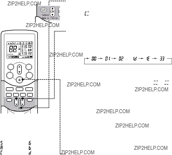
1.If the lamps are indicated as shown B to E in Table
2.When the remote controller is set to the service mode, the indoor controller diagnoses the operation condi- tion and indicates the information of the
HiPOWER ECO MEMO
1.3.5.9H
SWING FIX FAN SLEEP
1 Press [CHECK] button with a tip of pencil to set the remote controller to the service mode.
??????

 ??? is indicated on the display of the remote controller.
2 Press [ON ] or [OFF
 ] button
If there is no fault with a code, the indoor unit will beep once (Beep) and the display of the remote controller will change as follows :
??? ??? ???
???The TIMER indicator of the indoor unit flashes continuously. (5 times per 1 sec.)
???Check the unit with all 52 check codes ( 


 to
to 
 ) as shown in
???Press [ON  ] or [OFF
  ] button to change the check code backward.
CLOCK 
RESET 
ON OFF
CHECK
If there is a fault, the indoor unit will beep for 10 seconds (Beep, Beep, Beep...).
Note the check code on the display of the remote controller.
Alphanumeric characters are used for the check codes.
???
???All indicators on the indoor unit will flash. (5 times per 1 sec.)
3 Press [START/STOP] button to release the service mode.
???The display of the remote controller returns to as it was before service mode was engaged.
4 Time shortening method.
1.Press SET button while pushing CHECK button.
2.Press [START/STOP] button.
Fig.
??? 64 ???

1.After servicing, press the START/STOP button to return to the normal mode.
2.After servicing by the check code, turn off breaker of the power supply, and turn on breaker of the power supply again so that memory in the microcomputer returns the initial status.
However, the check codes are not deleted even if the power supply is turned off because they are stored in the fixed memory.
3.After servicing, press [CLR] button under check mode status and then send the check code ???7F??? to the indoor unit. The error code stored in memory is cleared.
Table
??? 65 ???

??? 66 ???
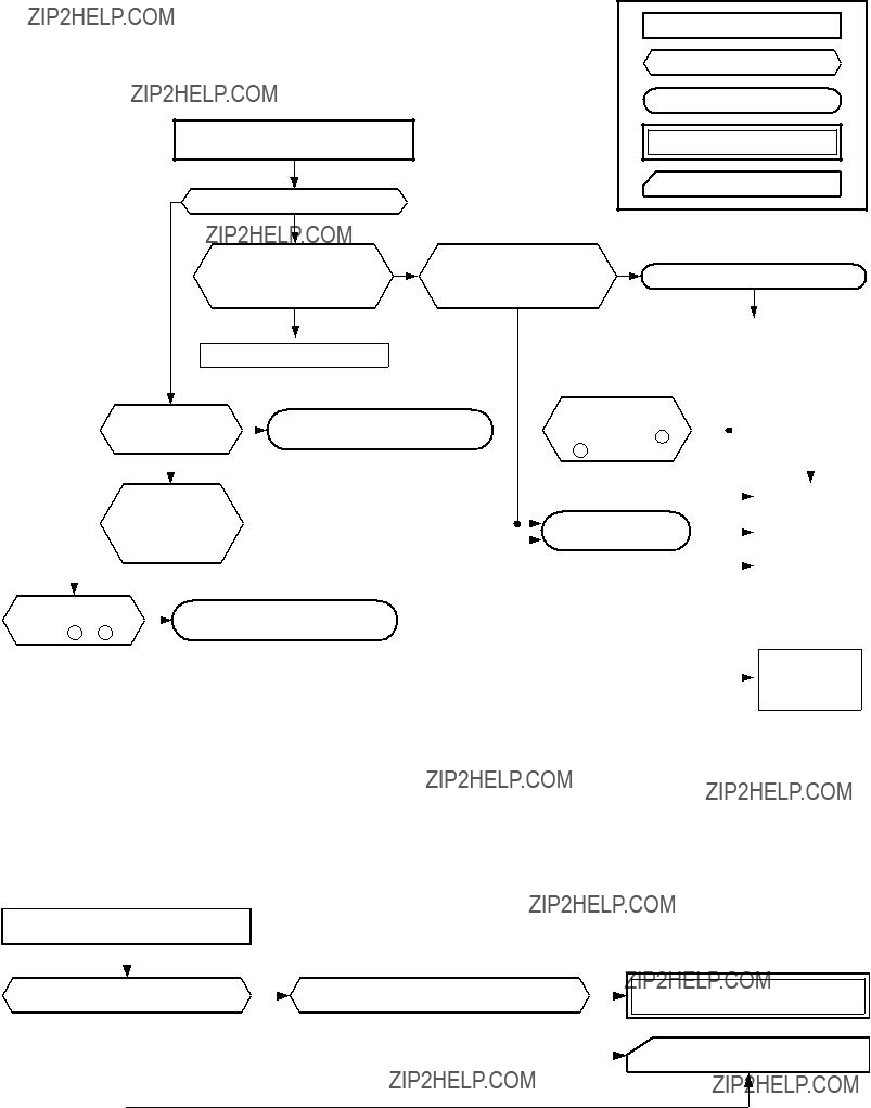
(1) Power is not turned on (Does not operate entirely)
???Be sure to disconnect the motor connector CN10 after shut off the power supply, or it will be a cause of damage of the motor.
(2) Power is not turned on though Indoor P.C. board is replaced
<Confirmation procedure>
Turn on power supply.
Correct wiring.
To item of
???Power supply is not turned on???.
??? 67 ???

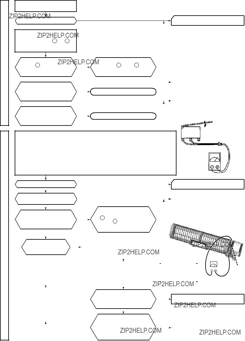
(3) Only the indoor motor fan does not operate
<Primary check>
1.Is it possible to detect the power supply voltage
2.Does the indoor fan motor operate in cooling operation?
(In heating operation, the indoor fan motor does not operate for approximately 10 minutes after it is turned on, to prevent a cold air from blowing in.)
Turn off power supply once, and turn it on again.
NO
YES
Start to operate indoor unit in cooling operation at airflow level ???LOW???.
Peplace indoor fan motor.
Peplace main P.C. board.
YES
Is it possible to NO change airflow level
to ???HIGH????
YES
Peplace bearing.
??? 68 ???

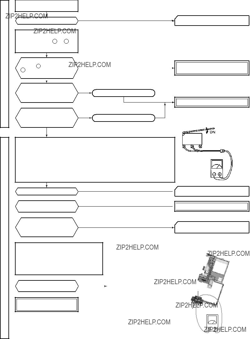
(4) Indoor fan motor automatically starts to rotate by turning on power supply
<Cause>
The IC is built in the indoor fan motor. Therefore the P.C. board is also mounted to inside of the motor.
If the P.C. board is soldered imperfectly or the IC is defective, the fan motor may automatically rotate by turning on power supply.
<Inspection procedure>
1.Remove the front panel. (Remove 2 screws.)
2.Remove the cover of the fan motor lead wires.
3.Check DC voltage with CN10 connector while the fan motor is rotating.
NOTE :
???Do not disconnect the connector while the fan motor is rotating.
???Use a thin test rod.
Indoor fan starts rotating when power supply is turned on.
(Check output DC voltage of fan motor on P.C. board.)
Measure voltage between 3 (GND : BLACK) and 5 (V line : YELLOW) of motor connector (CN10)
while indoor fan motor is rotating.
P.C. board
DC
??? 69 ???

(5) Troubleshooting for remote controller
<Primary check>
Check that A or B selected on the main unit is matched with A or B selected on the remote controller.
The unit does not beep at all.
Push the START/STOP button. Operation lamp on indoor
NOTE : After replacing batteries, push the RESET button with a tip of a pencil.
??? 70 ???
(1)Outdoor unit does not operate
1)Is the voltage between R and S of the indoor terminal block varied?
Confirm that transmission from indoor unit to outdoor unit is correctly performed based upon the follow- ing diagram.
NOTE:
???Measurement should be performed 2 minutes and 30 seconds after starting of the operation.
???Be sure to prepare a diode for judgment.
(2) Outdoor unit stops in a little while after operation started
<Check procedure> Select phenomena described below.
1)The outdoor unit stops 10 to 20 minutes after operation started, and 10 minutes or more are required to restart the unit.
2)If the unit stops once, it does not operate until the power will be turned on again.
To item of Outdoor unit does not operate.
3)The outdoor unit stops 10 minutes to 1 hour after operation started, and an alarm is displayed. (Discharge temp. error check code 03, 1E Sensor temp. error check code 02, 1C)
Gas leak
P.M.V. is defective.
Refer to the chart in
Miswiring of connecting wires of indoor/outdoor units
Clogging of pipe and
??? 71 ???

<Check procedure>
Valve drive check
NO
Is connecter of coil connected to inverter?
YES
Is positioning sound of valve (sound hitting to stopper) heard
from valve when the air conditioner starts the operation after turning off power NO of the air conditioner once?
YES
Set it correctly.
Set it correctly.
Replace coil valve.
Set it correctly.
Gas amount check and valve clogging check
Remove TC sensor connector from the P.C. board in indoor unit. (Remove connector from the P.C. board.)
Operate the air conditioner in COOL mode by TEMP button (???Beep??? sound is heard if keeping pushed for 10 seconds.).
The operation enters temporary operation mode which fixes opening degree of compressor speed. Check condensation at outlet of PMV, and then check operating pressure from the service port.
Check the operating pressure from service port, and add gas if pressure is low.
Replace valve.
Add gas.
??? 72 ???
Primary check
Turn off the power breaker once, and turn on again after 10 seconds.
Does the OPERATION indicator flash?
 YES
YES
Turn off the power breaker and remove CN34 (Micro switch connector).
Is DC12V applied between 1 (Red/DC12V) and
(Brown/GND) of CN1 of the
 YES
YES
Is there conduction of
 NO
NO
Is there conduction of
NO
To item ???Power supply is not turned on???
 YES
YES
1)Check operation while
2)Perform air purifying operation by the remote controller.
???In this time, check that the remote controller is in status which is shortened by time on the reactivation preventive timer and all display indicators go on for approx. 3 seconds when a signal is received.
( If time on the reactivation preventive timer is not shortened,) the
???While the air purifier operates, check that the fan speed [AUTO] is not displayed. (Because the power ON/OFF is controlled on the program)
3)Be sure not to touch the electric dust collector, ionizer, or ionized wire unit with the human body.
Push the switch ON ??? ON
Release the switch
???OFF
Tester
Operation check
??? 73 ???
Turn off the power breaker once, and turn on again after 10 seconds.
 YES
YES
Primary check
Turn off the power breaker and remove CN34 (Micro switch connector).
Is there conduction of
(Front panel opened)?
 NO
NO
Is there conduction of
(Front panel closed)?
YES
1)Check operation while
2)Perform air purifying operation by the remote controller.
???In this time, check that the remote controller is in status which is shortened by time on the reactivation preventive timer and all display indicators go on for approx. 3 seconds when a signal is received.
( If time on the reactivation preventive timer is not shortened,) the
???While the air purifier operates, check that the fan speed [AUTO] is not displayed. (Because the power ON/OFF is controlled on the program)
3)Be sure not to touch the electrode with the human body.
Replace the power P.C. board (MCC5020) or the housing assembly.
Replace
??? Conduction check of
 Push the switch
ON ??? ON
Release the switch ??? OFF
Tester
Does the indoor fan rotate?
 YES
YES
NO
 To item ???Only indoor fan does not operate???
Operation check
 YES
YES
Does the PURE indicator
go off within 2 seconds after YES it was ON, and does the FILTER
indicator (Orange) go on?
 NO
NO
Referring to the right figure, check the
In this time, peel the thermal insulator, and attach it to the original position after check operation.
NOTE :
Use an exclusive high voltage tester; otherwise the tester may be broken.
 NO
NO
 NO
NO
Replace the

 Replace the main P.C. board (MCC5020).
To item ???How to check whether the air purifier is good or not???
??? How to check output of minus ion <Caution on High Voltage!!>
Electrode
GND
??? 74 ???
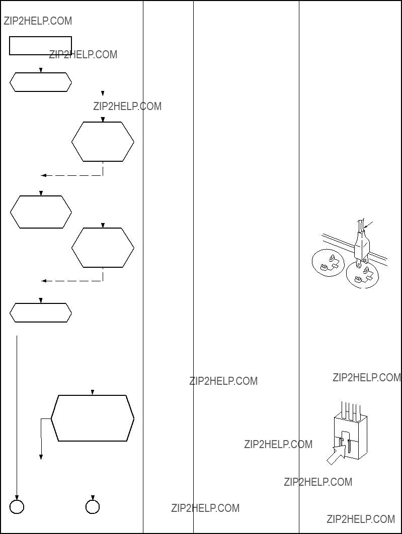
Table
??? 75 ???
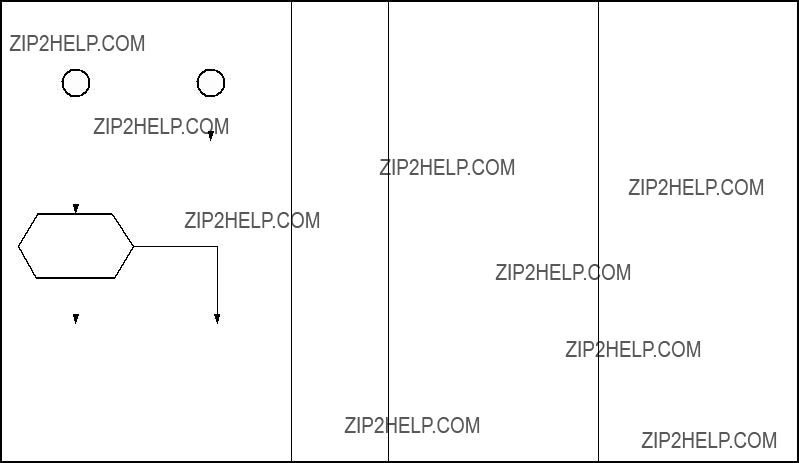
Check
compressor NG??? Winding is not opened. winding
resistance.
Check operation within 2 minutes 20 seconds after activation stopped.
(1)Operating precautions
1)When removing the front panel or the P.C. board, be sure to shut off the power supply breaker.
2)When removing the P.C. board, hold the edge of the P.C. board and do not apply force to the parts.
3)When connecting or disconnecting the connectors on the P.C. board, hold the whole housing. Do not pull at the lead wire.
(2)Inspection procedures
1)When a P.C. board is judged to be defective, check for disconnection, burning, or discoloration of the copper foil pattern or this P.C. board.
2)The P.C. board consists of the following 2 parts
a.Main P.C. board part :
DC power supply circuit (5V, 12V, 15V), Indoor fan motor control circuit, CPU and peripheral circuits, buzzer, and Driving circuit of louver.
b.Indication unit of infrared ray receiving infrared ray receiving circuit, LED :
To check defect of the P.C. board, follow the procedure described below.
??? 76 ???

(3) Check procedures
Table
??? 77 ???

GND
+12V
+5V
[1] Sensor characteristic table
Resistance value (k )
Temperature (??C)
??? 78 ???
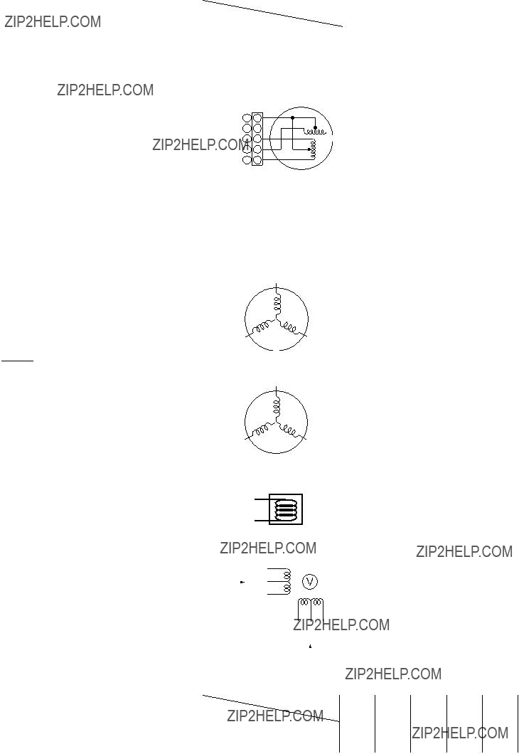
??? 79 ???

2.Completely discharge the four electrolytic capacitors.
3.Remove the diode block from the PCB (which is soldered in place).
4.Use a multimeter with a pointer to test the continuity, and check that the diode block has the proper rectification characteristics.
10 to 20 ??? when the multimeter probe is reversed
??? 80 ???
1.Symptom
???Outdoor fan motor does not rotate.
???Outdoor fan motor stops within several tens seconds though it started rotating.
???Outdoor fan motor rotates or does not rotate according to the position where the fan stopped, etc. Remote controller check code ???02 : Outdoor block, 1A : Outdoor fan drive system error???
2.Cause
The following causes are considered when the outdoor fan motor does not normally rotate. 1) Mechanical lock of the outdoor fan motor
2) Winding failure of the outdoor fan motor
3)
3.How to simply judge whether outdoor fan motor is good or bad
Turn OFF the breaker.
Disconnect two connectors (CN300) of the outdoor fan motor from the outdoor P.C. board.
Does the fan rotate without trouble when rotating it with hands?
of the connector (CN300 : Motor winding) is 17 to 25???, it is normal.
YES
NO
NO
CN300
(Outdoor P.C. board error)
NOTE :
However, GND circuit error inside of the motor may be accepted in some cases when the above check is performed.
When the fan motor does not become normal even if P.C. board is replaced, replace the outdoor fan motor.
??? 81 ???
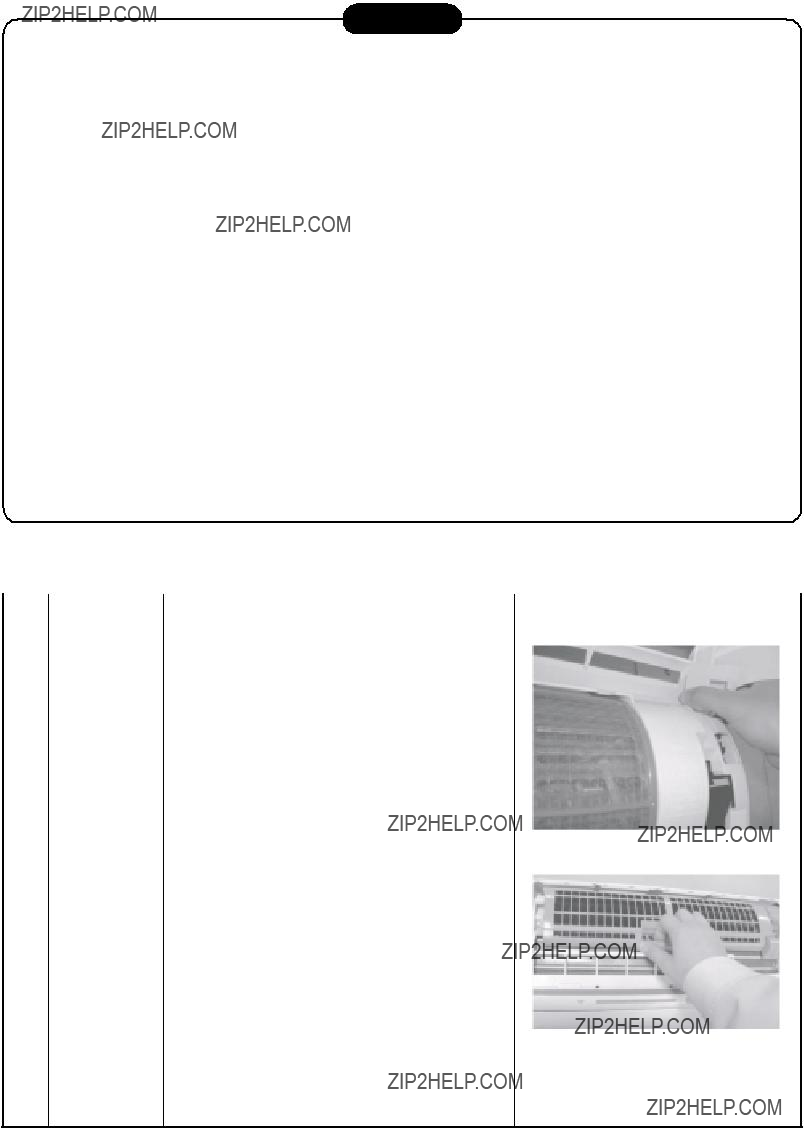
12. HOW TO REPLACE THE MAIN PARTS
WARNING
???Since high voltages pass through the electrical parts, turn off the power without fail before proceeding with the repairs.
Electric shocks may occur if the power plug is not disconnected.
???After the repairs have been completed (after the front panel and cabinet have been installed), perform a test run, and check for smoking, unusual sounds and other abnormalities.
If this check is omitted, a fire and/or electric shocks may occur. Before proceeding with the test run, install the front panel and cabinet.
???Ensure that the following steps are taken when doing repairs on the refrigerating cycle.
1.Do not allow any naked flames in the surrounding area.
If a gas stove or other appliance is being used, extinguish the flames before proceeding. If the flames are not extinguished, they may ignite any oil mixed with the refrigerant gas.
2.Do not use welding equipment in an airtight room.
Carbon monoxide poisoning may result if the room is not properly ventilated.
3.Do not bring welding equipment near flammable objects.
Flames from the equipment may cause the flammable objects to catch fire.
???If keeping the power on is absolutely unavoidable while doing a job such as inspecting the cir- cuitry, wear rubber gloves to avoid contact with the live parts.
Electric shocks may be received if the live parts are touched.
Proceed very carefully when conducting checks since directly touching the parts on the control circuit board may result in electric shocks.
3)Remove the left and right air filters, and remove the electric dust collector.
??? 82 ???

Pull here 
Installation plate
Press here
Press here
Front panel
Press
5)Remove the front panel fixing screws. (2 pcs.)
6)Press the electric parts box with the right thumb while pulling the both sides of the front panel toward you.
<How to assemble the front panel>
Protrusion
Protrusion
1)Press three center positions and two lower center positions of the air outlet, and then hang the hanging hooks (4 pcs.) at the top side of the front panel to the rear plate.
2)Insert the electric dust collector and left and right air filters.
Press in the electric dust collector until the protrusions on both sides are completely inserted into the holders.
If installation is incomplete, the FILTER indicator (orange) may light.
3)Tighten two screws.
???Incomplete hanging or incomplete pressing may cause a dewdrops or generation of a fluttering sound.
???83 ???

<How to assemble the high voltage generator>
1)Insert the high voltage generator straight into the evaporator, and secure it using the fixing screw.
Check whether the completely inserted.
2)Pass the leads of the high voltage generator through the area designated and insert them into its connectors.
Claw
3)Attach the air ionizer to the back body, and pass the two leads (black) through the area designated on the electric parts box assembly.
Claw
??? 84 ???

TC sensor
Fan motor connector
Louver moter connector
Screw
Fixing screw
5)Disengage the two claws at the top of the display unit.
<How to assemble the electric parts box>
1)Hook the top part of the electric parts box assembly onto the claws on the back body, and secure it using the fixing screw.
Now attach the display unit. Connect the connectors for the fan motor and louver motor.
2)Secure the grounding wire using the fixing screw. Insert the TC sensor into the sensor holder.
*Be absolutely sure to loop the grounding wire and TC sensor leads once at the bottom.
??? 85 ???
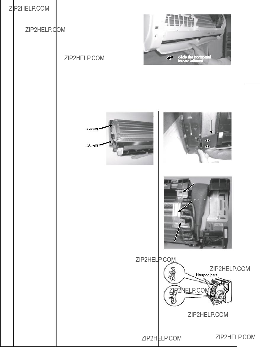
Disengage the claw
Heat exchanger fixing holder
Screw
5)Remove right side of the end plate from two fixing ribs while sliding slightly the
heat exchanger rightward.
??? 86 ???

<Caution at assembling>
???If the bearing is out from the housing, push it into the specified position and then incorporate it in the main body.
???After assembling the bearing base, check that it
Drain pipe
Drain pipe
Bearing base
??? 87 ???

Secure using the fixing screw
 Screw
Screw
Motor band (Right)
Screw
Secure using the fixing screw
Fan motor leads
4)Lift the left side of the heat exchanger, and pull out the cross flow fan.
Pull out here
??? 88 ???

??Cross flow fan <Caution at reassembling>
1)At assembling work of the bearing base, check that the drain pipe is surely incorpo- rated in the back body.
(Otherwise, water leak is caused.)
2)To incorporate the fan motor, remove the fan motor rubber (at shaft core side), incorporate the motor into the position in the following figure, and then install the fan motor.
Bearing base
Drain pipe
70.5mm
???Perform positioning of the fan motor as follows:
???When assembling the fan motor, the fan motor must be installed in such a way that the fan motor leads will be taken out is positioned at the bottom front.
???After assembling the two hooking claws of the motor band (right) into the main body, position the fan motor, insert it, and then secure the motor band (right) using the two fixing screws.
U groove
??? 89 ???

<P.C. board layout>
DB01
C03
T01
??? 90 ???
???Common 1. Detachment procedure
1) Stop operation of the air conditioner, and turn off the main switch of the breaker for air conditioner.
2) Remove the valve cover. (ST1T??4 ?? 8L 1 pc.)
??? After removing screw, remove the valve cover pulling it downward.
4)Remove the upper cabinet. (ST1T??4 ?? 8L 5 pcs.)
???After removing screws, remove the upper cabinet pulling it upward.
2.Attachment
1)Attach the
??? 91 ???

1) Perform step 1 in ???.
2) Remove the fixing screws (ST1T??4 ?? 8L
2 pcs.) used to secure the front cabinet and inverter cover, the screws (ST1T??4 ?? 8L 3 pcs.) used to secure the front cabinet at the bottom, and the fixing screws (ST1T??4 ?? 8L 2 pcs.) used to secure the motor base.
2.Attachment
1)Insert the claw on the front left side into the side cabinet (left).
Concave section
??? 92 ???

??? If removing the inverter cover in this condition, P.C. board can be checked.
??? If there is no space above the unit, perform work of 1 in ???.
Be careful to check the inverter because
NOTE
This capacitor is one with mass capacity. Therefore, it is dangerous that a large spark generates if  ,
,  polarity with screwdriver, etc. for discharging.
8) Disconnect connectors of various lead wires.
Requirement
As each connector has a lock mecha- nism, avoid to remove the connector by holding the lead wire, but by holding the connector.
Be sure to remove the connector by holding the connector, not by pulling the lead wire.
??? 93 ???
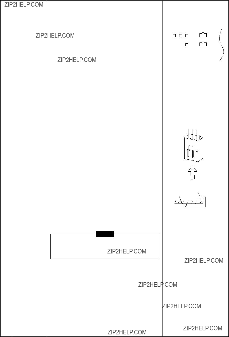
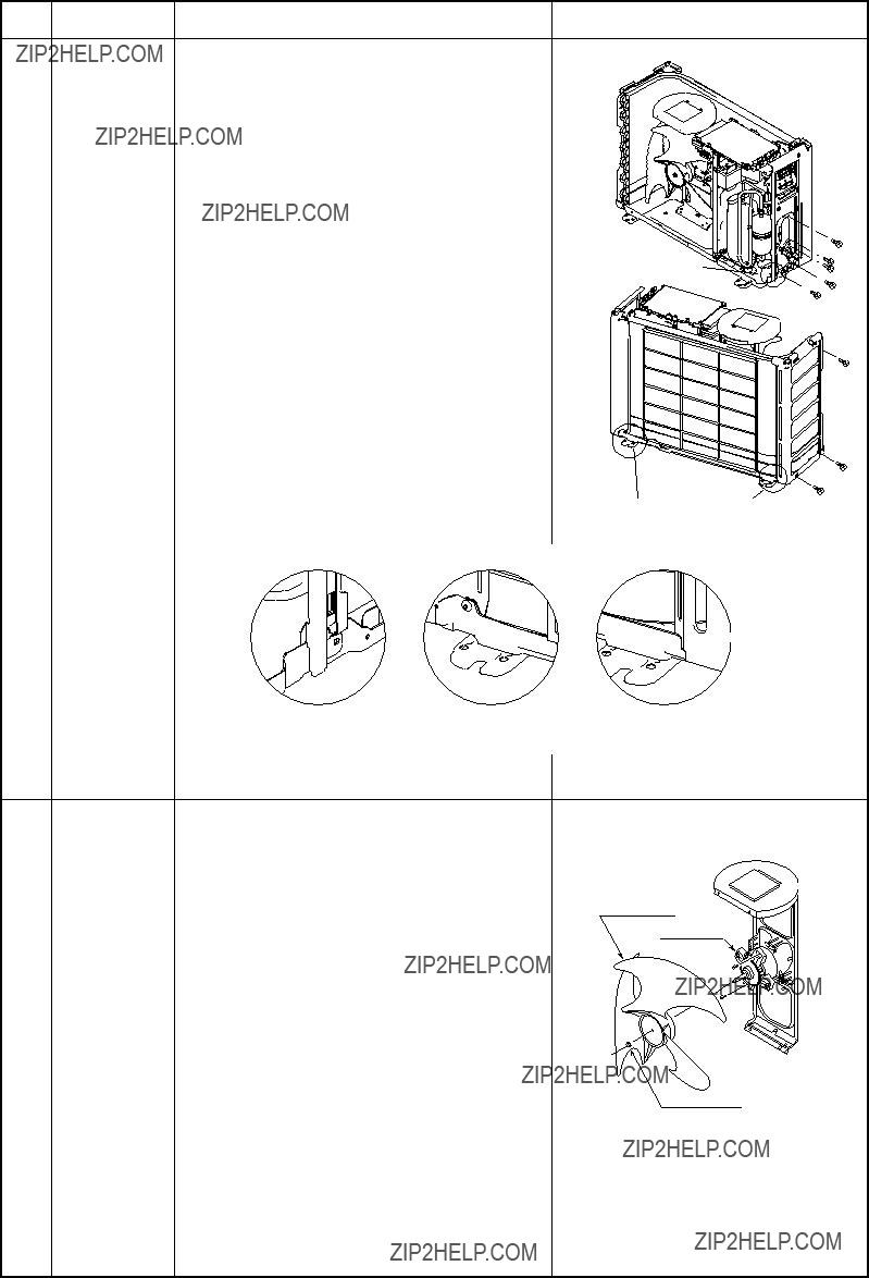


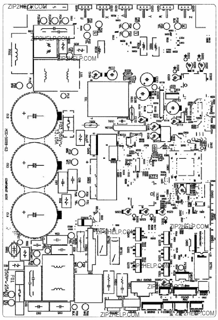
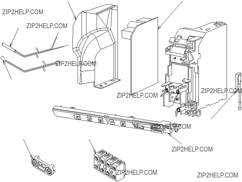


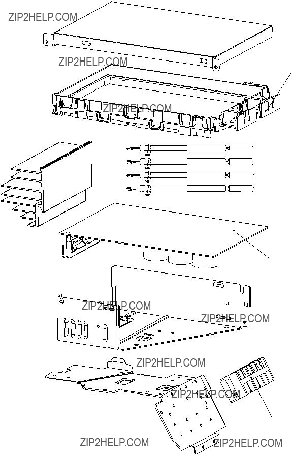


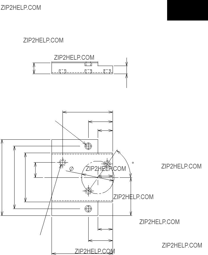


 Hooking claw
 Dryer
Dryer Earth leakage circuit breaker
  Power supply for air conditioner