I N S T A L L A T I O N I N S T R U C T I O N S
Universal Pitch-Adjustable Wall Mount
For Flat Panel Display PLP-91/D
Once the Universal Flat Panel Display Wall Mount Bracket is attached to your display, simply attach the mount securely on a wall, lock the display in place using the convenient Q-latch, and attach your audio/video cables.
The PLP-91/D is virtually invisible when your display is mounted.
BEFORE YOU BEGIN
???Caution: To prevent damage to the PLP-91/D, which could affect or void the Factory warranty, and to the equipment that will be attached to it, thoroughly study all instructions and illustrations before you begin the installation. Pay par- ticular attention to the ???Important Warnings and Precautions??? on Page 1.
???The mount is designed to be installed using wall studs or supporting framework. The fasteners used to anchor the mount must be capable of supporting five times the total weight of the equipment.
???The maximum weight to be installed on the Universal Pitch-Adjustable Wall Mount is 125 pounds (56.7 Kg).
Sony Electronics Inc. 8805-000087
1 Sony Drive
Park Ridge, NJ 07656 201-930-1000 www.sony.com/displaysystems

 IMPORTANT WARNINGS AND PRECAUTIONS!
WARNING: A WARNING alerts you to the possibility of serious injury or death if you do not follow the instructions.
CAUTION: A CAUTION alerts you to the possibility of damage or destruction of equipment if you do not follow the corre- sponding instructions.
??? WARNING:Improper installation can result in serious personal injury! Make sure that the structural members can support a weight factor five times the total weight of the equipment. If not, reinforce the structure before installing the mount.
???WARNING:Be aware also of the potential for personal injury or damage to the unit if it is not adequately mounted.
???WARNING:The installer is responsible for verifying that the wall to which the mount is anchored will safely support
the combined load of all attached components or other equipment.
???WARNING:Watch for pinch points. Do not put your fingers between movable parts.
???WARNING:Make sure the mount and brackets are correctly oriented.
???WARNING:Make sure the latching flag securing the display is completely engaged at all times except when removing
or installing the display. The latching flag must be all completely engaged when installing/removing cables.
???CAUTION: Check the unit for shipping damage before you begin the installation.
???CAUTION: Use only the mounting screws provided and DO NOT OVER TIGHTEN mounting screws.
TOOLS REQUIRED FOR INSTALLATION
???Phillips screwdrivers, No. 1 and No. 2 TIP
???Drill and bit set
???Wrench set
NOTE: Other tools may be required depending on the method of installation.
Installation InstructionsPitch-Adjustable Mount PLP91/D
PARTS
Table 1: Parts
I N S T A L L A T I O N I N S T R U C T I O N S
PSB-91/D
PLASMA DISPLAY MOUNTING BRACKET
Prior to assembly, unpack carton completely and verify contents.
If you are missing any of the following components, please contact Customer Service at 1-800/582-6480
BEFORE PROCEEDING, READ INSTALLATION INSTRUCTIONS COMPLETELY
PLASMA DISPLAYS ARE EXTREMELY FRAGILE.
ALL COMPONENTS MUST BE SECURELY FASTENED TO A
STRUCTURAL MEMBER CAPABLE OF SUPPORTING 4
TIMES THE COMBINED WEIGHT OF ALL COMPONENTS
PLUS THE EQUIPMENT BEING MOUNTED. IF IT CANNOT
SUPPORT THIS WEIGHT, THE STRUCTURE MUST BE
REINFORCED.
THE MAXIMUM WEIGHT TO BE INSTALLED ON THE MOUNT IS 125 POUNDS (56.7 KG).
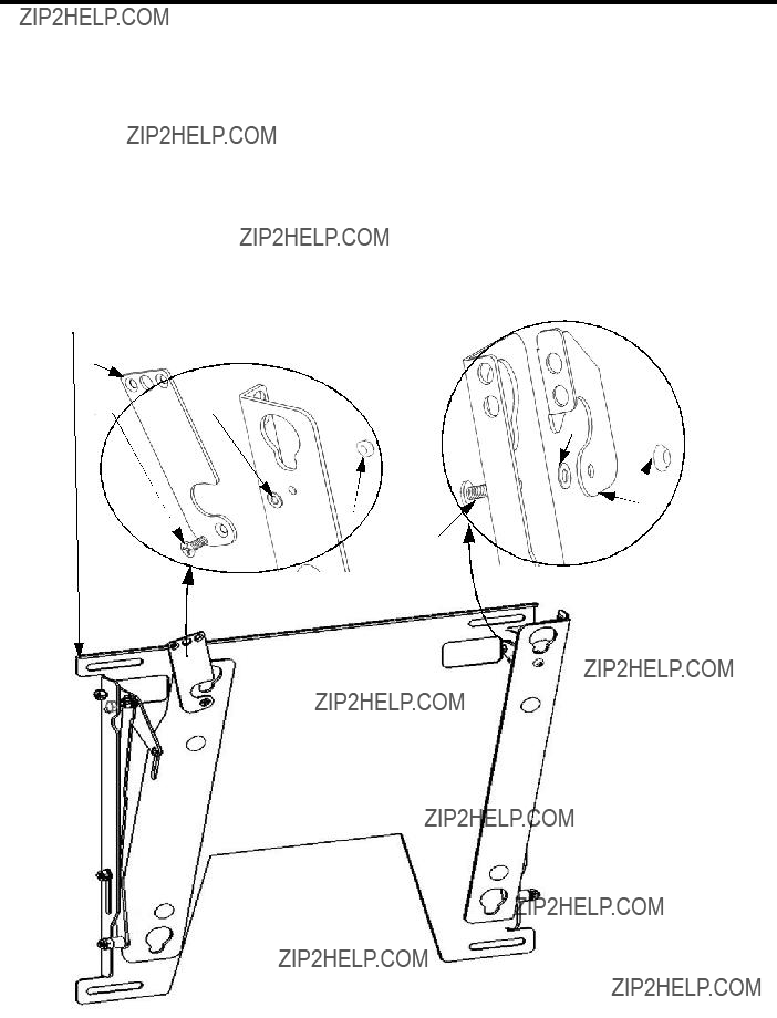
1.Using a 10-24 button head cap screw inserted from back side of bracket, secure mounting button, with chamfered hole of mounting button (larger surface) facing bracket, to bracket (four places) (see Figure 2 & Figure 3).
1 Sony Drive
Park Ridge, NJ 07656 201-930-1000 www.sony.com/displaysystems
2.Place Nylon spacers over mounting holes on back of screen.
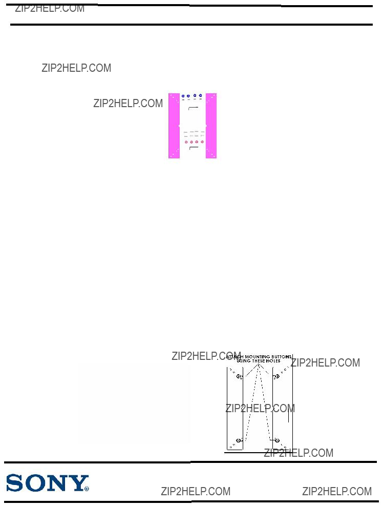
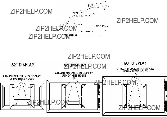
3.Attach mounting brackets to the display using the M5 screws for 32??? screen or M6 for 42??? and 50??? screens (see Figure 4 & Figure 5).
4.With the aid of another person, lift your display up to the mount, aligning buttons of mounting brackets with slots in the mount.
5.Lower safety catch on the mount to secure your display, making sure latch is completely engaged.
Figure 4
Figure 5


 Holes
Holes
 Holes
Holes