Video and Audio
Interfacing Guide Book
Video and Audio
Interfacing Guide Book

Sony is a registered trademark of Sony Corporation Belden is a registered trademark of Cooper Industries Windows is a registered trademark of Microsoft Corporation
IBM is a registered trademark of International Business Machines Corporation Windows NT is a registered trademark of Microsoft Corporation
Memory Stick is a trademark of Sony Corporation Betacam is a trademark of Sony Corporation FlexSys is a trademark of Sony Corporation
All other trademarks are property of their respective owners

Routing Switcher Reference Guide
Routing Switcher Features
Notes:
*An entry in the ???Maximum cascadable matrix size??? column indicates that routers of this type can be cascaded to form larger matrix, up to the maximum shown. Cascade sets are required.
**Maximum
***SDTI is defined as SMPTE305M.
2

Routing Switcher Reference Guide
3

Routing Switcher Reference Guide
Routing Switcher Options
4
Routing Switcher Reference Guide
5

Routing Switcher Reference Guide
Backup CPU boards
Each type of backup CPU board is identical to the main CPU board it supports. If the main CPU fails, the backup CPU automatically takes over all control functions and the router continues to function normally.
Backup Power Supply Units
A routing switcher backup Power Supply Unit (PSU) is a valuable option in critical applications, such as
6

I/F Processor Functional Index
7
I/F Processor Cross Reference Guide
8
I/F Processor Cross Reference Guide
9

10

Routing Switchers
Routing Switchers
11

Routing Switchers
Routing Switchers
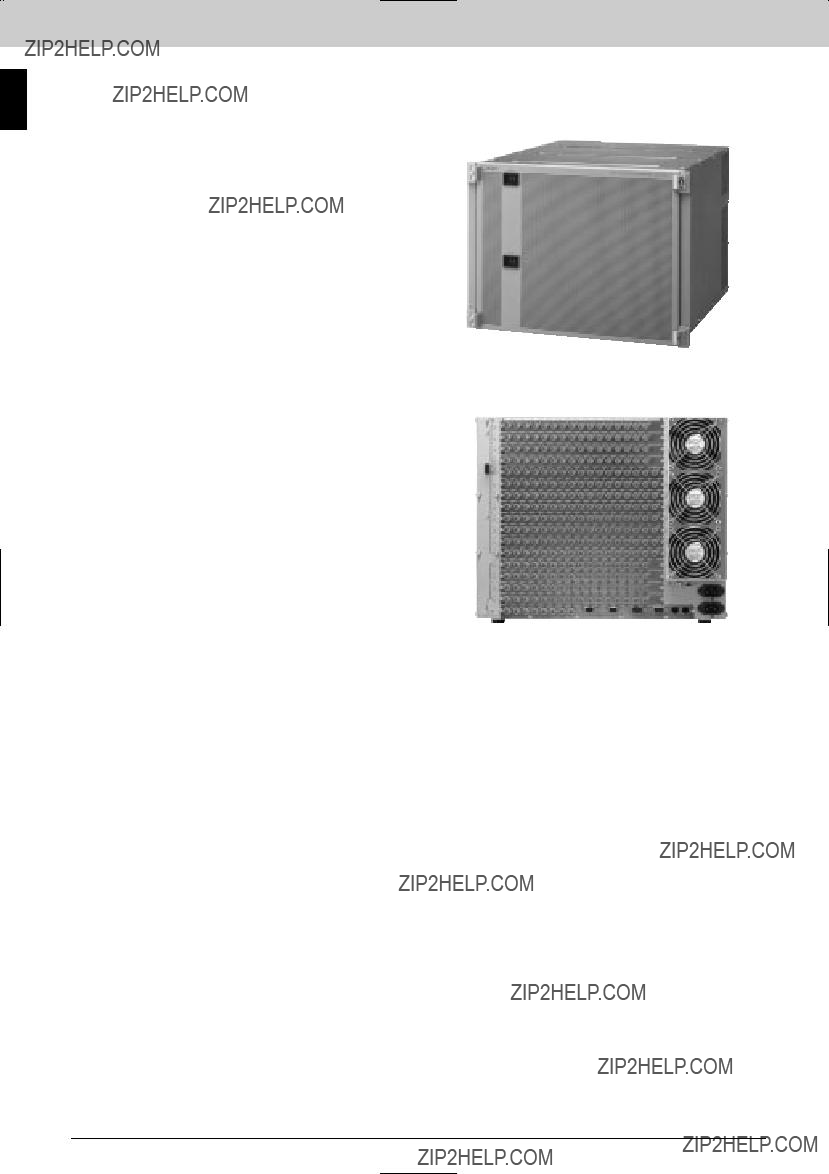
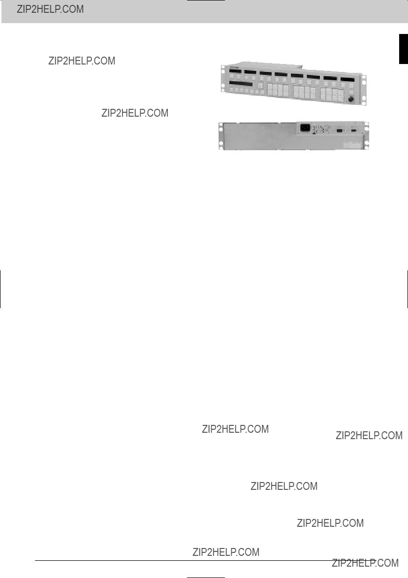
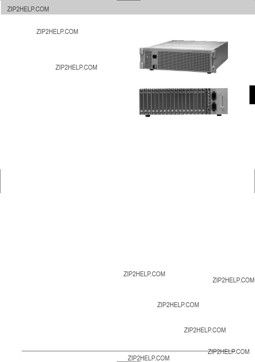
The
Features
*Highly flexible, multi
??? 264 x 272 in 22R U *Flexible input and output configurations ??? Increments of 33 inputs and/or 34 outputs; HD/SD input and output options; SD input and output options
Supplied Accessories
Operation manual (1)
Optional Boards
Optional Peripherals
Optional Software
Rear Panel
12

Routing Switchers
Specifications
Inputs/outputs
Serial digital input:
SDI IN connector (BNC type)
(up to 264 in steps of 33) 0.8
Channel coding: Scrambled NRZI
Cable length SD options:
200 m max. (With Belden 8281, Fujikura 5C2V or equivalent coaxial cable)
HD/SD options:
100 m max. (With Belden 1694A, Fujikura 5CFB or equivalent coaxial cable)
Input return loss SD options:
15 dB or more (5 MHz to 360 MHz) HD/SD options:
15 dB or more (5 MHz to 1.485 GHz) Serial digital output:
SDI OUT connector (BNC type) (Up to 272 in steps of 34)
Signal standard SD options:
4:2:2 component serial digital signal (SDI), conforming to
HD/SD options:
HD component serial digital signal (HD SDI), conforming to SMPTE292M
Data transfer rate SD options:
143 Mb/s to 360 Mb/s HD/SD options:
143 Mb/s to 1.485 Gb/s
SD options:
143, 177, 270, 360 Mb/s HD/SD options:
143, 177, 270, 360, 540 Mb/s; 1.485/1.001, 1.485 Gb/s
Output return loss SD options:
15 dB or more (5 MHz to 360 MHz) HD/SD options:
15 dB or more (5 MHz to 1.485 GHz)
REMOTE 1 Connector:
BNC type (4) Protocol:
Sony
312 kb/s (1250 kb/s will be supported in the future)
Data transfer method:
Cable length:
500 m max. (With Belden 8281, Fujikura 5C2V or equivalent coaxial cable)
REMOTE 2 Connector:
Protocol:
Sony Cart+ Data transfer rate:
38.4 kb/s
REMOTE 3 Connector:
ALARM OUT:
Mini
REF IN:
BNC (4), with
NETWORK:
General
Power requirements:
AC 100 V to 240 V, 50 to 60 Hz Power consumption:
Approx. 900 W (fully loaded) Operating temperature:
5 to 40 ??C (41 to 104 ??F) Operational humidity:
10 to 90% (no condensation) Dimensions (W x H x D)
440 x 974 x 520 mm
(17 3 /8 x 38 3 /8 x 20 1 /2 inches) (Without projections)
Mass:
Approx. 90 kg (fully loaded) (198 lb)
Service parts: Extension Board
Routing Switchers
13
Routing Switchers
Routing Switchers
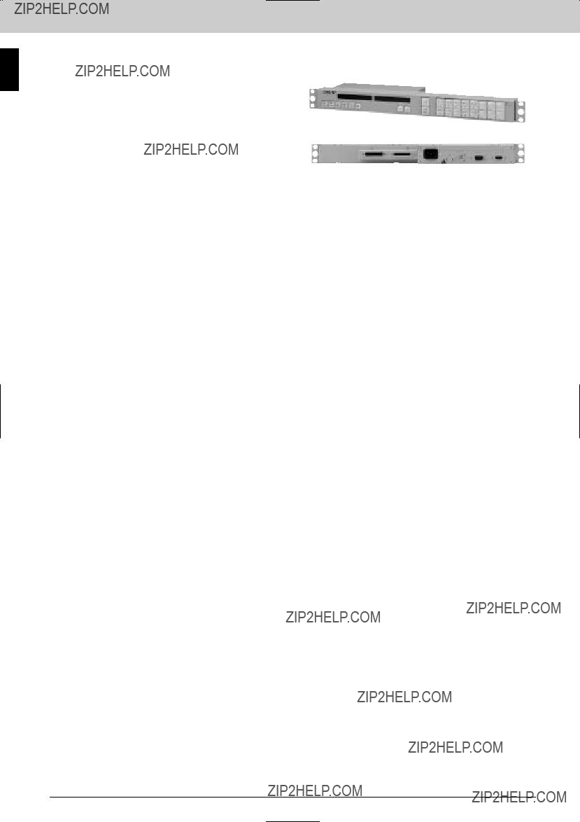
The
Features
*A range of highly flexible, multi
*SDI (143, 177, 270, 360 Mb/s and 540 Mb/s) * SDTI (270 Mb/s) * HD SDI (1.485 and 1.485/1.001 Gb/s) * Flexible input and output configurations in increments of 16 channels * HD SDI/SD SDI input and output options *
Rear Panel
Supplied Accessories
Operation manual (1) Installation manual (1) Maintenance manual (1) 75 ?? teminator (1)
BNC
Optional Accessories
Optional Boards
Optional Software
Optional Peripherals
Specifications
Inputs/outputs
REMOTE 1:
312 kb/s
Data transfer method:
500 m (with Belden 8281, Fujikura 5C2V or equivalent 75 ?? coaxial cable). Isolator/Expander Expandable to 1000 m with a
REMOTE 2:
Complies with
38.4 kb/s Protocol:
Cart+ REMOTE 3:
Complies with
9.6/38.4 kb/s DTR control, 8 bits, no parity, 1 stop bit
REMOTE 4:
ALARM OUT:
Parallel (relay) (2 connecting points) Mini
REF IN:
NETWORK:
General
Power requirements:
100 to 240 V AC, 50/60 Hz Power consumption:
650 W (128 x 128, 1.5 Gb/s) Operational temperature:
5 to 40 ??C (41 to 104 ??F) Operational humidity:
10 to 90% Dimensions (W x H x D):
440 x 354 x 520 mm
(17 3/8 x 14 x 20 1/2 inches) Mass:
Approx. 20 kg (44 lb 1 oz) (without modules)
Service parts: Extension Board, Maintenance Manual Part II, Protocol Manual
14
Routing Switchers
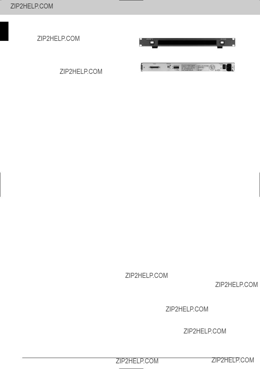
The
Features
* A range of highly flexible, multi
Rear Panel
Routing Switchers
Supplied Accessories
Operation manual (1) Installation manual (1) Maintenance manual (1) 75 ?? teminator (1)
BNC
Optional Accessories
Optional Boards
Optional Software
Optional Peripherals
Specifications
Inputs/outputs
REMOTE 1:
312 kb/s
Data transfer method:
500 m (with Belden 8281, Fujikura 5C2V or equivalent 75 ?? coaxial cable).
Expandable to 1000 m with a
REMOTE 2:
Complies with
38.4 kb/s Protocol:
Cart+ REMOTE 3:
Complies with
9.6/38.4 kb/s DTR control, 8 bits, no parity, 1 stop bit
REMOTE 4:
ALARM OUT:
Parallel (relay) (2 connecting points) Mini
REF IN:
NETWORK:
General
Power requirements:
100 to 240 V AC, 50/60 Hz Power consumption:
330 W (64 x 64, 1.5 Gb/s) Operational temperature:
5 to 40 ??C (41 to 104 ??F) Operational humidity:
10 to 90% Dimensions (W x H x D):
440 x 176 x 520 mm
(17 3/8 x 7 x 20 1/2 inches) Mass:
Approx. 15 kg (33lb 1 oz) (without modules)
Service parts: Extension Board, Maintenance Manual Part II, Protocol Manual
15

Routing Switchers
Routing Switchers
The
signal breakaway, phantom operation of
memory by a
Features
* A range of highly flexible, multi
Supplied Accessories
Operation manual (1) Installation manual (1) Maintenance manual (1) 75 ?? teminator (1)
BNC
Optional Accessories
Optional Boards
Optional Software
Optional Peripherals
Specifications
Inputs/outputs
REMOTE 1:
312 kb/s
Data transfer method:
500 m (with Belden 8281, Fujikura 5C2V or equivalent 75 ?? coaxial cable).
Expandable to 1000 m with a
REMOTE 2:
Complies with
38.4 kb/s Protocol:
Cart+ REMOTE 3:
Complies with
9.6/38.4 kb/s DTR control, 8 bits, no parity, 1 stop bit
REF IN:
NETWORK:
General
Power requirements:
100 to 240 V AC, 50/60 Hz Power consumption:
70 W (16 x 16, 1.5 Gb/s) Operational temperature:
5 to 40 ??C (41 to 104 ??F) Operational humidity:
10 to 90% Dimensions (W x H x D):
440 x 43.6 x 520 mm
(17 3/8 x 1 3/4 x 20 1/2 inches) Mass:
Approx. 8.5 kg (18 lb 12 oz) (without modules)
Service parts: Extension Board, Maintenance Manual Part II, Protocol Manual
16

Routing Switchers
The
Features
* Matrix size up to 128 x 128 * Handles analog video, AES/EBU audio and analog audio in blocks of 32 inputs and 32 outputs to form square or rectangular matrix * Typical audio matrix configuration ??? I/O 1
Supplied Accessories
Routing Switchers
17
Routing Switchers
Routing Switchers
Specifications
Control
REMOTE 1: Standard
Connector type: BNC type (3)
Protocol:
Transfer speed: 312 kb/s/1250 kb/s REMOTE 2:
Connector type:
Protocol: Sony CART+ protocol
Transfer speed: 38.4 kb/s REMOTE 3:
Connector type:
Protocol: Terminal/ISR/Data Backup
Transfer speed: 9600 b/s/38.4 kb/s REMOTE 4:
Monitor
Video connectors: BNC type
Inputs return loss:
More than 40 dB DC to 5 MHz Clamping:
Pedestal clamping or DC coupled Frequency response:
100 kHz to 10 MHz,
10 MHz to 30 MHz,
Less than 0.1% DP:
Less than 0.1 ?? Signal to noise ratio:
More than 73 dB at 5 MHz Crosstalk:
Less than
Analog audio
Inputs connector:
Inputs impedance:
20 k?? /600 ?? internally selectable Max inputs level:
+24 dBm, balanced Converter:
ADC 48 kHz/20 bits, Linear, AES/EBU digital audio
Frequency response:
20 Hz to 20 kHz,
0.05% or less (1 kHz, reference level,
30 kHz low pass filter) Signal to noise ratio:
More than 90 dB (30 kHz low pass filter) Crosstalk:
Less than
DAC 48 kHz/20 bits Maximum output level:
+24 dBm into 600 ?? balanced. Output impedance:
Approx. 20 ?? Output connector:
AES / EBU digital audio
Inputs connector:
BNC type
Signal standards: AES/EBU specification 75 ?? , unbalanced
Inputs signal level: 1
Max inputs cable length:
600 m max. (When using a Belden 8281, Fujikura 5C2V or equivalent coaxial cable)
Reference:
Word sync and analog video signal Outputs connector:
BNC type
General
Power requirements:
100 to 240 V AC, 50/60 Hz Power consumption:
600 VA max. Dimensions (W x H x D):
424 x 620 x 550 mm
(16 3/4 x 24 1/2 x 21 3/4 inches) Mass:
Approx. 40 kg (88.18 lb)
Service parts: Extension board
18
Routing Switchers
The
Features
* 16 x 16 switching matrix for
Routing Switchers
Supplied Accessories
AC power cord (for U.S.A and Canada) (1) AC power cord (for Europe and U.K.) (1) AC plug adaptor (1)
75 ?? terminators (4)
Plug holder B (black) (1) Plug holder B (gray) (1) Operation manual (1)
Maintenance manual (1) Installation manual (1)
Optional Accessories
Optional Boards
Optional Peripherals
Specifications
Inputs/outputs
REF IN connectors (BNC type) (2), high impedance, analog video, one is for
Cascade inputs:
CASCADE IN
Cascade outputs:
CASCADE OUT
AC power inputs:
Remote control connectors
REMOTE 1:
Cable length: 500 m max. (when using a Belden 8281, Fujikura 5C2V or equivalent coaxial cable)
Checksum: HDLC
Rear Panel
REMOTE 2:
Complying with
REMOTE 3:
Complying with
General
Power requirements:
100 to 240 V AC, 50/60 Hz
1.3 to 0.8 A Power consumption:
70 W
Operating temperature:
5 to 40 ??C (41 to 104 ??F) Storage temperature:
482 x 354.4 x 450 mm
(19 x 14 x 17 3/4 inches) (Excluding projecting parts)
Mass:
Approx. 25 kg (55 lb 2 oz)
19
Routing Switchers
Routing Switchers
The
Features
* 32 x 32 switching matrix for time code signals * Expandable to provide a maximum matrix size of 256 x 256 *
Supplied Accessories
AC power cord (for U.S.A and Canada) (1) AC power cord (for Europe and U.K.) (1) AC plug adaptor (1)
75 ?? terminators (4) T bridge (1)
Plug holder B (black) (1) Plug holder B (gray) (1) Operation manual (1)
Maintenance manual (1) Installation manual (1)
Optional Boards
Optional Peripherals
Specifications
Inputs/outputs
Time code inputs:
XLR
XLR
REF IN connectors (BNC type) (2), high impedance, analog video, one is for
Cascade inputs:
CASCADE IN
Cascade outputs:
CASCADE OUT
AC power inputs:
Remote control connectors
REMOTE 1:
Cable length: 500 m max. (When using a Belden 8281, Fujikura 5C2V or equivalent coaxial cable)
Checksum: HDLC
Rear Panel
REMOTE 2:
Complying with
REMOTE 3:
Complying with
General
Power requirements:
100 to 240 V AC, 50/60 Hz
1.3 to 0.8 A Power consumption:
70 W
Operating temperature:
5 to 40 ??C (41 to 104 ??F) Storage temperature:
482 x 354.4 x 450 mm
(19 x 14 x 17 3/4 inches) (Excluding projecting parts)
Mass:
Approx. 25 kg (55 lb 2 oz)
20

Routing Switchers
The
Features
* 32 x 32 switching matrix for analog audio signals *
Transformer I/O *
Rear Panel
Routing Switchers
Supplied Accessories
Operation manual (1) Installation manual (1) Maintenance manual (1) 75 ?? terminators (3)
Optional Accessories
Optional Peripherals
Specifications
Inputs/outputs ???
Reference video signal inputs:
REF IN connectors (BNC type) (2), high impedance, analog audio signal, with
Remote control connectors REMOTE 1 A, B, C:
SPACE
Data transfer rate: 312.5 kb/s
Cable length: 500 m max. (When using a Belden 8281, Fujikura 5C2V or equivalent coaxial cable ) Checksum: HDLC
x 16 + x 12 + x 5 + 1 REMOTE 2:
Complies with
REMOTE 3:
Complies with
(Fixed with M2.6 screws) (1) Terminal:
9600 b/s, DTR control,
ISR:
9600 b/s,
Audio signals
Audio signal inputs:
100 k?? /600 ?? (selectable) Standard input/output level:
+4 dBm Maximum input level:
+24 dBm Maximum output level:
+24 dBm (600 ?? load, balanced) Frequency response:
60.1 dB
(20 kHz to 20 kHz, 1 kHz+4 dBm) Distortion:
0.01% (20 Hz to 20 kHz, with +24 dBm output)
Crosstalk:
Less than
(30 kHz LPF, nominal)
General
Power requirements:
100 to 240 V AC, 50/60 Hz Current consumption:
1.2 to 0.6 A
(With all optional boards installed) Operating temperature:
5 to 40 ??C (41 to 104 ??F)
Dimensions (W x H x D): 424 x 132 x 500 mm
(16 3/4 x 5 1/4 x 19 3/4 inches) Mass:
Approx. 16 kg (35 lb 4 oz)
(With all optional boards installed)
21

Routing Switchers
Routing Switchers
The
* 32 x 32 switching matrix for composite analog video signals *
Supplied Accessories
Operation manual (1) Installation manual (1) Maintenance manual (1) 75 ?? terminations (3)
Optional Accessories
Optional Boards
Optional Peripherals
Specifications
Inputs/outputs ???
Reference video signal inputs:
REF IN connectors (BNC type) (2), high impedance, analog video signal, with
Remote control connectors REMOTE 1 A, B, C:
Cable length: 500 m (when using a Belden 8281, Fujikura 5C2V or equivalent coaxial cable)
Checksum: HDLC
REMOTE 2:
Complies with
REMOTE 3:
Complies with
(Fixed with M2.6 screws) (1) Terminal:
9600 b/s, DTR control
9600 b/s
Video signals
DG:
Less than 0.5% (1
Less than 5?? (1
60.2 dB (100 kHz to 8 MHz) Crosstalk:
Less than
Less than 61%
(Between two inputs at 4.43 MHz)
More than 65 dB (5 MHz, low pass) Input return loss:
More than 42 dB K factor:
Less than 0.5% Tilt:
Less than 1% Output gain stability:
60.1 dB
General
Power requirements:
100 to 240 V AC, 50/60 Hz Current consumption:
1.2 to 0.6 A
(With all optional boards installed) Operating temperature:
5 to 40 ??C (41 to 104 ??F) Dimensions (W x H x D):
424 x 132 x 500 mm
(16 3/4 x 5 1/4 x 19 3/4 inches) Mass:
Approx. 16 kg (35 lb 4 oz)
(With all optional boards installed)
22

Routing Switchers
The
Routing Switchers
control panel.
Features
Rear Panel
*Router control in
*Alternate source switching using Chop function * Sources selectable to levels * Sources searched by category * Access can be restricted to a defined block of crosspoints * Large selector buttons show source and destination name (Status shown by button color) * Several crosspoints switchable with a single button (Phantom function) * Route function for expanded sources * Number of sources and destinations controlled expandable with additional units * Control bridge between
Applicable Models
Switcher
Supplied Accessories
Operation and maintenance manual (1) BNC
Specifications
Control signals
REMOTE 1:
Data transfer method:
Data transfer rate: 312.5 kb/s Max. cable length 500 m
(when using Belden 8281, Fujikura 5C2V or equivalent 75 ?? coaxial cable). Expandable to 1000 m with a
REMOTE 2:
Data transfer method: Conforms to the EIA
Data transfer rate: 38.4 kb/s
Data transfer method:
Data transfer rate: 19.2 kb/s
General
Power requirements:
100 to 240 V AC, 50/60 Hz Current consumption:
0.35 A
Operating temperature:
0 to 45 ??C (32 to 113 ??F) Dimensions (W x H x D):
440 x 44 x 120 mm
(17 3/8 x 1 3/4 x 4 3/4 inches) Mass:
Approx. 1.5 kg (3 lb 5 oz)
23
Routing Switchers
Routing Switchers
The
shallow depth of the unit makes it easy to accommodate the
Features
Rear Panel
*Router control in
*Reduced depth helps in desk mounting applications
Applicable Models
Switcher
Supplied Accessories
Operation and maintenance manual (1) BNC
Specifications
Control signal
REMOTE 1:
Data transfer method:
Data transfer rate: 312.5 kb/s
Max. cable length 500 m (when using Belden 8281, Fujikura 5C2V or equivalent 75 ?? coaxial cable). Expandable to 1000 m with a
REMOTE 2:
Data transfer method: conforms to the EIA
Data transfer rate: 38.4 kb/s
Data transfer method:
Data transfer rate: 19.2 kb/s
General
Power requirements:
100 to 240 V AC, 50/60 Hz Current consumption:
0.20 A
Operating temperature:
0 to 45 ??C (32 to 113 ??F) Dimensions (W x H x D):
440 x 44 x 120 mm
(17 3/8 x 1 3/4 x 4 3/4 inches) Mass:
Approx. 1.5 kg (3 lb 5 oz)
24
Routing Switchers
The
Features
* Router control in
the Preset window (with 16 alpha/ numerical symbols) *Rear Panel Three source/destination selection systems available *
BPS (D) Selection
Routing Switchers
Applicable Models
Switcher
Supplied Accessories
Operation and maintenance manual (1) BNC
Specifications
Control signal
REMOTE 1:
Data transfer method:
Data transfer rate: 312.5 kb/s
Max. cable length 500 m (when using Belden 8281, Fujikura 5C2V or equivalent 75 ?? coaxial cable). Expandable to 1000 m with a
REMOTE 2:
Data transfer method: Conforms to the EIA
Data transfer rate: 38.4 kb/s
Data transfer method:
Data transfer rate: 19.2 kb/s
General
Power requirements:
100 to 240 V AC, 50/60 Hz Current consumption:
0.4 A
Operating temperature:
0 to 45 ??C (32 to 113 ??F) Dimensions (W x H x D):
440 x 88 x 120 mm
(17 3/8 x 3 1/2 x 4 3/4 inches) Mass:
Approx.1.5 kg (3 lb 5 oz)
25

Routing Switchers
Routing Switchers
The
shallow depth of the unit makes it easy to accommodateRear Panel the
control panel.
Features
*Router control in
*Reduced depth helps in desk mounting applications
Applicable Models
Switcher
Supplied Accessories
Operation and maintenance manual (1) BNC
Specifications
Control signal
REMOTE 1:
Data transfer method:
Data transfer rate: 312.5 kb/s
Max. cable length 500 m (when using Belden 8281, Fujikura 5C2V or equivalent 75 ?? coaxial cable). Expandable to 1000 m with a
REMOTE 2:
Data transfer method: Conforms to the EIA
Data transfer rate: 38.4 kb/s
Data transfer method:
Data transfer rate: 19.2 kb/s
General
Power requirements:
100 to 240 V AC, 50/60 Hz Current consumption:
0.25 A
Operating temperature:
0 to 45 ??C (32 to 113 ??F) Dimensions (W x H x D):
440 x 44 x 120 mm
(17 3/8 x 1 3/4 x 4 3/4 inches) Mass:
Approx. 1.5 kg (3 lb 5 oz)
26

Routing Switchers
The
Rear Panel
Features
*Router control in
*Improved monitor function for the selection of destinations * Alternate source switching using Chop function * Sources selectable to levels * Sources searched by category * Access can be restricted to a defined block of crosspoints * Large selector buttons show source and destination name (Status shown by button color) * Several crosspoints switchable with a single button (Phantom function) * Route function for expanded sources * Number of sources and destinations controlled expandable with additional units * Control bridge between
*Single cable connection * Reduced depth helps in desk mounting applications
Routing Switchers
Applicable Models
Switcher
Supplied Accessories
Operation and maintenance manual (1) BNC
Specifications
Control signal
REMOTE 1:
Data transfer method:
Data transfer rate: 312.5 kb/s
Max. cable length 500 m (when using Belden 8281, Fujikura 5C2V or equivalent 75 ?? coaxial cable). Expandable to 1000 m with a
REMOTE 2:
Data transfer method: Conforms to the EIA
Data transfer rate: 38.4 kb/s
Data transfer method:
Data transfer rate: 19.2 kb/s
General
Power requirements:
100 to 240 V AC, 50/60 Hz Current consumption:
0.25 A
Operating temperature:
0 to 45 ??C (32 to 113 ??F) Dimensions (W x H x D):
440 x 44 x 120 mm
(17 3/8 x 1 3/4 x 4 3/4 inches) Mass:
Approx. 1.5 kg (3 lb 5 oz)
27
Routing Switchers
Routing Switchers
Features
*Router control in
*Sources selectable to levels * Large selector buttons show source and destination name (Status shown by button color) * Several crosspoints switchable with a single button (Phantom function) * Route function for expanded sources * Number of sources and destinations controlled expandable with additional units * Control bridge between
Applicable Models
Switcher
Supplied Accessories
Operation and maintenance manual (1) BNC
Specifications
Control signal
REMOTE 1:
Data transfer method:
Data transfer rate: 312.5 kb/s
Max. cable length 500 m (when using Belden 8281, Fujikura 5C2V or equivalent 75 ?? coaxial cable). Expandable to 1000 m with a
REMOTE 2:
Data transfer method: Conforms to the EIA
Data transfer rate: 38.4 kb/s
Data transfer method:
Data transfer rate: 19.2 kb/s GPI I/O:
General
Power requirements:
100 to 240 V AC, 50/60 Hz Current consumption:
0.25 A
Operating temperature:
0 to 45 ??C (32 to 113 ??F) Dimensions (W x H x D):
440 x 44 x 120 mm
(17 3/8 x 1 3/4 x 4 3/4 inches) Mass:
Approx. 1.5 kg (3 lb 5 oz)
28
Routing Switchers
Applicable Models
Switcher
Supplied Accessories
Operation and maintenance manual (1) BNC
Specifications
Control signal
REMOTE 1:
Data transfer method:
Data transfer rate: 312.5 kb/s
Max. cable length 500 m (when using Belden 8281, Fujikura 5C2V or equivalent 75 ?? coaxial cable). Expandable to 1000 m with a
REMOTE 2:
Data transfer method: Conforms to the EIA
Data transfer rate: 38.4 kb/s
Data transfer method:
Data transfer rate: 19.2 kb/s GPI I/O:
General
Power requirements:
100 to 240 V AC, 50/60 Hz Current consumption:
0.25 A
Operating temperature:
0 to 45 ??C (32 to 113 ??F) Dimensions (W x H x D):
220 x 88 x 120 mm
(17 3/8 x 1 3/4 x 4 3/4 inches) Mass:
Approx. 1.5 kg (3 lb 5 oz)
29

Routing Switchers
Routing Switchers
The
Features
* Router control in
Entry
Rear Panel
Applicable Models
Switcher
Supplied Accessories
Operation and maintenance manual (1) BNC
Specifications
Control signal
REMOTE 1:
Data transfer method:
Data transfer rate: 312.5 kb/s
Max. cable length 500 m (when using Belden 8281, Fujikura 5C2V or equivalent 75 ?? coaxial cable). Expandable to 1000 m with a
REMOTE 2:
Data transfer method: Conforms to the EIA
Data transfer rate: 38.4 kb/s
Data transfer method:
Data transfer rate: 19.2 kb/s GPI I/O:
General
Power requirements:
100 to 240 V AC, 50/60 Hz Current consumption:
0.35 A
Operating temperature:
0 to 45 ??C (32 to 113 ??F) Dimensions (W x H x D):
440 x 88 x 120 mm
(17 3/8 x 1 3/4 x 4 3/4 inches) Mass:
Approx. 2.1 kg (4 lb 10 oz)
30

Routing Switchers
The
the
and are 1U high.
Features
*Signal information display in router systems * Display of source, destination, source line number and source status
*Large displays with
Applicable Models
Supplied Accessories
Operation and maintenance manual (1)
BNC
Tally label (1)
AC plug adapter (1)
AC power cords (2)
Specifications
Inputs/outputs ???
Parallel control:
INPUT connector
(1)
3 to 24 V DC Low: 0.0 to 0.6 V
High: 3.0 V and higher Control signal:
REMOTE (BNC type) (1),
312.5 kb/s Cable length:
500 m max. (when using a Belden 8281, Fujikura 5C2V or equivalent coaxial cable)
General
Power requirements:
100 to 240 V AC, 50/60 Hz Power consumption:
11 W
Operating temperature:
5 to 40 ??C (41 to 104 ??F) Dimensions (W x H x D):
483 x 44 x 150 mm
(19 1/8 x 1 3/4 x 6 inches) Mass:
Approx. 2.4 kg (5 lb 5 oz)
Routing Switchers
31
Routing Switchers
Routing Switchers
Features
*Signal information display in router systems * Display of source, destination, source line number and source status
*Large displays with
Applicable Models
Supplied Accessories
Operation and maintenance manual (1)
BNC
Tally label (1)
AC plug adapter (1)
AC power cords (2)
Specifications
Inputs/outputs ???
Parallel control:
INPUT connector
(1)
3 to 24 V DC Low: 0.0 to 0.6 V
High: 3.0 V and higher Control signal:
REMOTE (BNC type) (1),
312.5 kb/s Cable length:
500 m max. (when using a Belden 8281, Fujikura 5C2V or equivalent coaxial cable)
General
Power requirements:
100 to 240 V AC, 50/60 Hz Power consumption:
20 W
Operating temperature:
5 to 40 ??C (41 to 104 ??F) Dimensions (W x H x D):
483 x 44 x 150 mm
(19 1/8 x 1 3/4 x 6 inches) Mass:
Approx. 2.5 kg (5 lb 10 oz)
Rear Panel
32

Routing Switchers
The
Features
*Provides primary station control or
The
Routing Switchers
Applicable Models
Supplied Accessories
Operation manual (1) Installation manual (1)
Optional Board
Optional Software
Specifications
Remote ???
Remote 1:
Connectors: BNC type (3)
Transfer speed:
312 Kb/s / 1250 Kb/s Signal level:
1.8 V+/- 0.3 V (75 ?? ),
1.1 V+/- 0.3 V (75 ?? ) Remote 2:
Connectors:
CART++ Transfer speed: 38.4 Kb/s
Remote 3:
38.4 Kb/s
DATA LAN: Ethernet Connector:
TIME CODE
Connector:Rear Panel BNC type (1)
General
Power requirement:
12 V (Supplied from the
Power consumption: 1000 mA
Operating temperature:
5 to 40 ??C (41 to 104 ??F) Storage temperature:
10 to 90% Dimensions
Board (H x W): 112.2 x 388.3 mm
(4 1/2 x 15 3/8 inches) Connector panel (W x H x D):
130 x 152.5 x 38 mm
(5 1/8 x 6 1/8 x 1 1/2 inches) Mass:
Approx. 900 g (1 lb 16 oz)
33

Routing Switchers
Routing Switchers
The
Features
* Provides primary station control or
System redundancy using two
Routing switcher
ISR
The BKPF Series function boards install in both the
Applicable Models
Supplied Accessories
Operation manual (1)
Installation manual (1)
Slot number label (1)
Routing switcher data backup software
Optional Software
Software
Specifications
General
Power requirements:
+5 V DC (supplied from the
Current consumption: 700 mA
Operating temperature:
5 to 40 ??C (41 to 104 ??F) Operating humidity:
10 to 90 % Dimensions (H x W)
Board:
195 x 310 mm
(7 3/4 x 12 1/4 inches) Connector panel:
195 x 25 mmRear Panel
(7 3/4 x 1 inches)
Mass Board:
Approx. 520 g (1 lb 2 oz) Connector panel:
Approx. 160 g (6 oz)
34

Routing Switchers
The
Applicable Models
Routing Switchers
Rear Panel
35

Routing Switchers
Routing Switchers
Features
* Installs in a PC for rapid setting up and
Applicable Models
Optional Board
Specifications
Note:
Routing Switchers
* Used as a primary station:
*Used as a secondary station:
Control Panels
*Used as a secondary station:
36
Routing Switchers
Features
* Installs in a
Applicable Models
Routing Switchers
37
Routing Switchers
Routing Switchers
38
Cables
Cables
39

Cables
Cables
Specifications
Applicable Models
Specifications
40

Common Accessories
Common Accessories
41

Common Accessories
Common Accessories
The
Applicable Models
Switcher
42

Interface Processor SP Series
Interface Processor SP Series
43

Interface Processor SP Series
Interface Processor SP Series
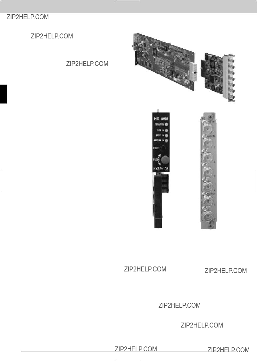
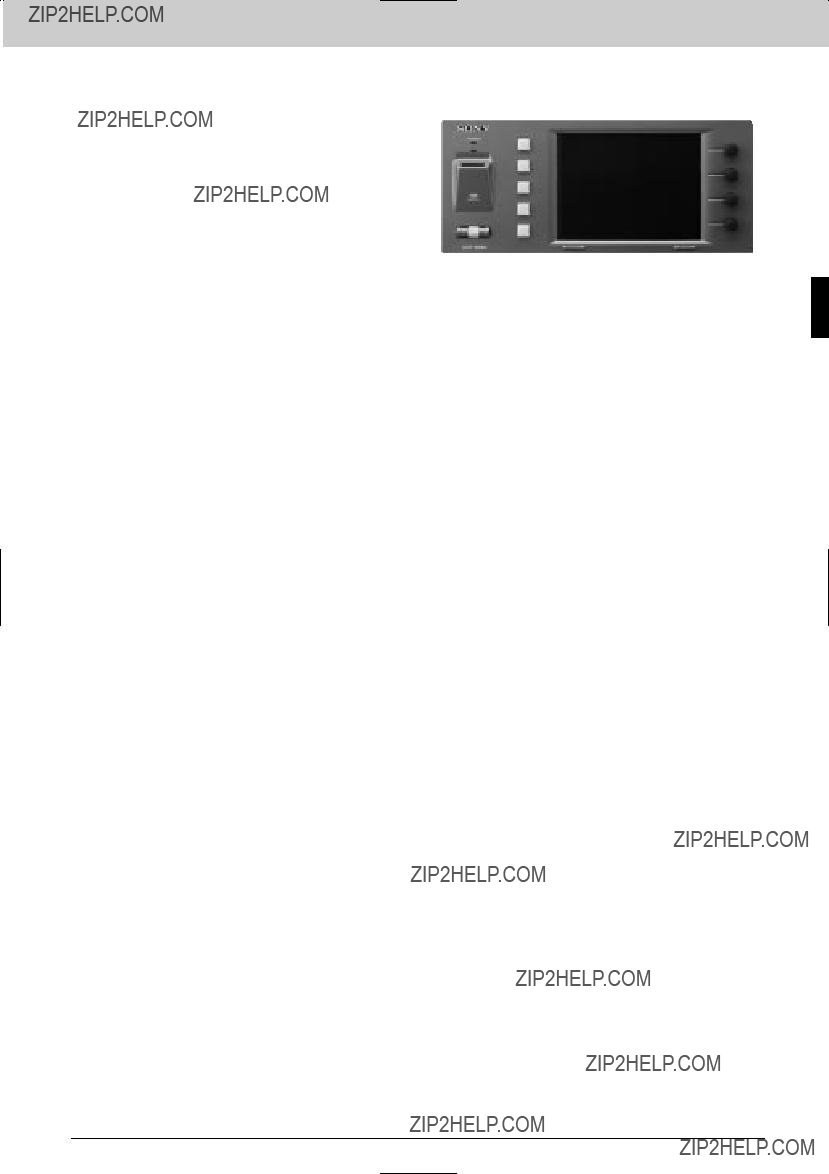
The
Features
*Compact,
from SD to HD; Both HD
Supplied Accessories
Operation manual (1)
Installation manual (1)
Optional Boards
General
Power requirements:
100 to 240 V AC, 50/60 Hz Power supply capacity:
+12 V DC: Max 4.4 A Operating temperature:
5 to 40 ??C (41 to 104 ??F) Storage temperature:
10 to 90% (no condensation) Dimensions (W x H x D):
440 x 43.2 x 550 mm
(21 3/4 x 1 3/4 x 17 3/8 inches)
Service part: Maintenance manual
Optional Peripherals
Specifications
Inputs/outputs
Remote:
HD
Status output:
STATUS OUT
(mini
44
Interface Processor SP Series
The
Features
*Compact and
black burst signal can be used *Networking applicationsRear Panel
??? Enab les the setting, controlling, and up/downloading of the
Interface Processor SP Series
Supplied Accessories
Operation manual (1)
Installation manual (1)
Optional Boards
General
Power requirements:
100 to 240 V AC, 50/60 Hz Current drain
100 V AC: Max 3.5 A, 240 V AC: Max 1.5 A
Power supply capacity: +12 V DC: Max 18.7 A
Operating temperature:
5 to 40 ??C (41 to 104 ??F) Storage temperature:
10 to 90% (no condensation) Dimensions (W x H x D):
440 x 550 x 132.4 mm
(5 1/4 x 21 3/4 x 17 3/8 inches) Mass:
Approx. 10 kg (22 lb 1 oz) (Not including optional boards)
Optional Peripherals
Specifications
Inputs/outputs
Remote:
Service part: Maintenance manual
HD
Status output:
STATUS OUT (mini
45

Interface Processor SP Series
Interface Processor SP Series
The
Features
Installation manual (1)
Installation guide (1)
46
Interface Processor SP Series
Specifications
Inputs/outputs
Video standard: 1035/60, 59.94i 1080/60, 59.94i, 50i
1080/30PsF, 29.97PsF, 25PsF, 24PsF, 23.976PsF
HD component serial digital signal (HD SDI):
Conforming to
Serial digital video input:
SDI IN connector (BNC type) (1) Reference input:
REF IN connector (BNC type) (1) 0.43
Black Burst or
SDI OUT connector (BNC type) (3) 0.8
Reference output:
Passive
GPI:
REMOTE connector (Mini
(1)
General
Power requirements: +12 V DC: 1.7 A
(Supplied from
Operating temperature:
5 to 40 ??C (41 to 104 ??F) Storage temperature:
10 to 90% (no condensation) Dimensions
Board (H x W): 112.2 x 388.3 mm
(4 1/2 x 15 3/8 inches) Connector Panel (H x D x W):
130 x 152.5 x 38 mm
(5 1/8 x 6 1/8 x 3/4 inches)
Mass Board:
Approx. 680 g (1 lb 8 oz) Connector Panel:
Approx. 300 g (11 oz)
Service part: Maintenance manual
HD SDI IN
REF IN
PASSIVE
Interface Processor SP Series
47

Interface Processor SP Series
Interface Processor SP Series
The
Features
* Multi
The
Applicable Models
Supplied Accessories
Install guide (1)
Install manual (1)
Expansion harness (1)
48
Interface Processor SP Series
Specifications
- Inputs/outputs -
Serial digital video input:
SDI in connectors (BNC type) (8) Data transfer rates:
143 Mb/s to 1.485 Gb/s Input signal:
Scrambled NRZI, 0.8
75 ?? , unbalanced Input return loss:
15 dB or more (5 MHz to 1.485 GHz) Cable length:
100 m max. (When using a
Reference inputs:
Supplied through the REF IN connectors on the
REF IN connectors (BNC type) (2) Black Burst or
Serial digital video output:
SDI out connectors (BNC type) (4) Data transfer rates:
143 Mb/s to 1.485 Gb/s
143, 177, 270, 360, 540 Mb/s: 1.485/1.001, 1.485 Gb/s
Output amplitude: 0.8
Rise/fall time: 270 ps or less
Output return loss:
15 dB or more (5 MHz to 1.485 GHz) Remote:
312.5kb/s
-General -
Power requirements: +12 V DC: 2.0 A
Operating temperature:
5 to 40 ??C (41 to +104 ??F) Storage temperature:
10 to 90% (no condensation)
Dimensions Board (H x W):
112.2 x 388.3 mm
(4 1/2 x 15 3/8 inches) Connector panel (W x H x D):
130 x 152.5 x 38 mm
(5 1/8 x 6 1/8 x 1 1/2 inches)
Mass Board:
Approx. 450 g (16 oz) Connector panel:
Approx. 300 g (11 oz)
Service part: Maintenance manual
INPUT
SDI IN x 8
Interface Processor SP Series
49
Interface Processor SP Series
Interface Processor SP Series
The
Features
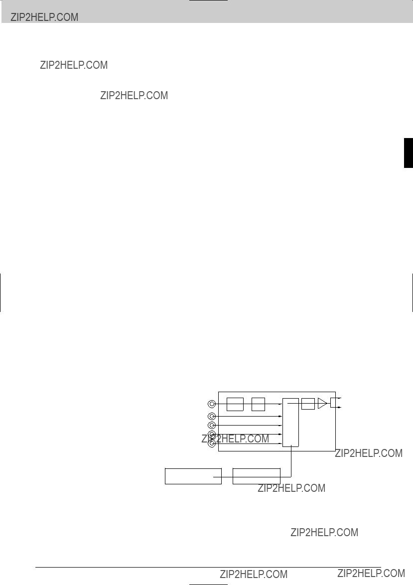
*Multiplexes four AES/EBU signals with an HD SDI signal *Audio delay adjustable (maximum two video frames) *Auto selection of HD
*External reference input
The
Applicable Models
Supplied Accessories
Operation manual (1)
Installtion manual (1)
Slot number label (1)
50
Interface Processor SP Series
Specifications
Inputs/outputs
Digital video signal input:
HD SDI IN connector (BNC type) (1) HD serial digital signal conforming to SMPTE291M/292M/299M, 1.4835 or 1.485 Gb/s
Input impedance: 75 ?? , unbalanced
Input return loss:
15 dB or more (5 MHz to 1.485 GHz) Transmission loss:
20 dB or less (at 742.5 MHz) Cable length:
100 m max. (When using a
Reference inputs:
Supplied through the REF IN connectors on the
REF IN connectors (BNC type) (2) Black Burst or
Digital audio signal inputs:
DIGITAL IN AUDIO connectors (BNC type) (4)
75 ?? , unbalanced Input return loss:
25 dB or more Input level:
1.1 to 0.1
HD SDI OUT connectors (BNC type) (2) HD serial digital signal conforming to SMPTE291M/292M/299M, 1.4835 or 1.485 Gb/s
Output level:
800 m
75 ?? , unbalanced Output return loss:
15 dB or more (5 MHz to 1.485 GHz) Rise/fall time:
Less than 270 ps Alignment jitter:
Within 135 ps
Digital input/output system delay
Video:
Less than 1.4 ??s
General
Power requirements:
+12 V DC: less than 1.0 A Power consumption:
Approx. 12 W Operating temperature:
5 to 40 ??C (41 to 104 ??F) Storage temperature:
10 to 90 % (without condensation) Dimensions:
Board (H x W): 112.2 x 388.3 mm
(4 1/2 x 15 3/8 inches) Connector panel (H x D x W):
130 x 152.5 x 19 mm
(5 1/8 x 6 1/8 x 25/35 inches)
Mass Board:
Approx 400 g (14 oz) Connector panel:
Approx. 220 g (8 oz)
Service parts: Extension boards
Interface Processor SP Series
51

Interface Processor SP Series
Interface Processor SP Series
The
Features
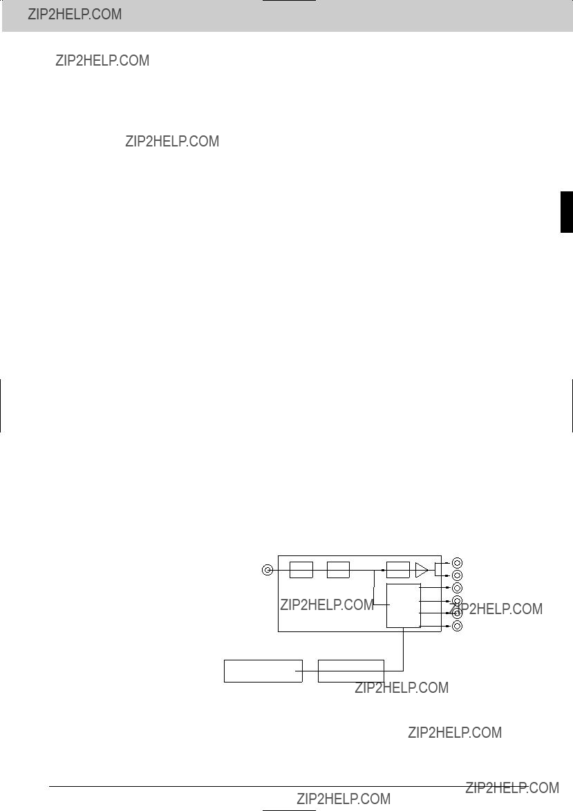
Series Signal Processing Unit)
The
Applicable Models
Supplied Accessories
Operation manual (1)
Installtion manual (1)
Slot number label (1)
52
Interface Processor SP Series
Specifications
Inputs/outputs
Digital video signal input:
HD SDI IN connector (BNC type) (1) HD serial digital signal conforming to SMPTE291M/292M/299M, 1.4835 or 1.485 Gb/s
Input impedance: 75 ?? , unbalanced
Input return loss:
15 dB or more (5 MHz to 1.485 GHz) Transmission loss:
20 dB or less (at 742.5 MHz) Cable length:
100 m max. (When using a
Reference inputs:
Supplied through the REF IN connectors on the
REF IN connectors (BNC type) (2) Black Burst or
Digital signal outputs:
HD SDI OUT connectors (BNC type) (2) HD serial digital signal conforming to SMPTE291M/292M/299M, 1.4835 or 1.485 Gb/s
Output level:
800 m
75 ?? , unbalanced Output return loss:
15 dB or more (5 MHz to 1.485 GHz) Rise/fall time:
Less than 270 ps Alignment jitter:
Within 135 ps
Digital audio signal outputs:
DIGITAL AUDIO OUT connectors (BNC type) (4)
AES3 digital audio signal Output impedance:
75 ?? , unbalanced Output level:
1.0
Digital input/output system delay
Video:
Less than 1.4 ??s
General
Power requirements:
+12 V DC: less than 1.0 A Power consumption:
Max. 12 W Operating temperature:
5 to 40 ??C (41 to 104 ??F) Storage temperature:
10 to 90 % (without condensation) Dimensions:
Board (H x W): 112.2 x 388.3 mm
(4 1/2 x 15 3/8 inches) Connector panel (H x D x W):
130 x 152.5 x 19 mm
(5 1/8 x 6 1/8 x 25/35 inches)
Mass Board:
Approx 400 g (14 oz) Connector panel:
Approx. 220 g (8 oz)
Service parts: Extension boards
Interface Processor SP Series
53

Interface Processor SP Series
Interface Processor SP Series
With an
Features
*Networking applications; Enables the setting, control, and up/downloading of the
Sony System Manager, Multiple control panels can operate with multiple processors *Redundant CPU available by installing two
The
Applicable Models
Supplied Accessories
Installation guide (1) Installation manual (1) 3.5 inches floppy disk (1)
Specifications
Operating humidity:
10 to 90% (no condensation) Dimensions
Board (H x W): 112.2 x 388.3 mm
( 4 1/2 x 15 3/8 inches) Connector panel (W x H x D):
130 x 152.5 x 19 mmFront Panel (5 1/8 x 6 1/8 x 25/32 inches)
Rear Panel
Option Boards
INT BUS
REF A
REF B
54

Interface Processor SP Series
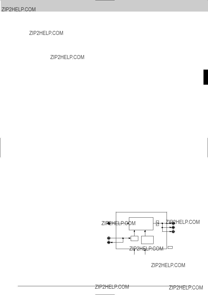
The
Features
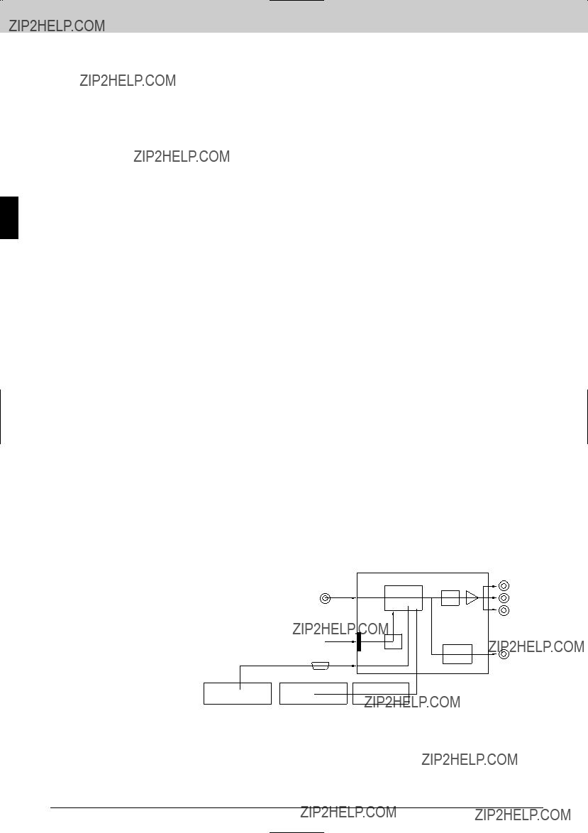
*Down converts an HD SDI signal to an SD SDI (D1) signal; From 1035(1125) / 59.94i, 29.97PsF to 480(525) / 59.94i, 29.97PsF, From 1080(1125) / 59.94i, 29.97PsF to 480(525), / 59.94i, 29.97PsF, From 1080(1125) / 50i, 25PsF to 576(625) / 50i, 25PsF *Provides an analog composite monitor output *Handles eight embedded audio channels *Retains ancillary data (VITC) and UMID that are on an HD SDI input to an SD SDI output *Output signal aspect ratio modes selectable from Squeeze, Edge Crop, Letter Box (16:9) and Semi Letter Box (13:9. 14:9,
15:9) *Minimum delay/frame delay selectable *Remotely controllable from an optional
The
Applicable Models
Supplied Accessories
Operation manual (1)
Installtion manual (1)
Slot number label (1)
Now
Printing
REMOTE
Interface Processor SP Series
55
Interface Processor SP Series
Interface Processor SP Series
Specifications
Inputs/outputs
Digital video signal input:
HD SDI IN connector (BNC type) (1) HD serial digital video signal conforming to SMPTE291M/292M/299M Input impedance:
75 ?? , unbalanced Input return loss:
15 dB or more (5 M to 1.5 GHz) Transmission loss:
Less than 20 dB Cable length:
100 m max. (when using a
Data rate:
1.4835 or 1.485 Gb/s Reference inputs:
Supplied through the REF IN connectors on the
REF IN connectors (BNC type) (2), Black Burst
Digital video outputs:
D1 SDI OUT 1, 2, 3 (BNC type) (1 each) 525/625 component serial digital video signal conforming to SMPTE259M Output impedance:
75 ?? , unbalanced Amplitude:
800
15 dB or more (5 M to 270 MHz) Cable length:
200 m max. (when using a
Data rate: 270 Mb/s
Analog video output:
Monitor output connector (BNC type) (1) NTSC/PAL composite video signal Output impedance:
75 ?? , unbalanced Amplitude:
1.0
90 H/1 video frames selectable
General
Power supply:
+12 V DC: 1.0 A
Power consumption: Approx. 12W
Operating temperature:
5 to 40 ??C (41 to 104 ??F) Storage temperature:
10 to 90% Dimensions:
Board (H x W): 112.2 x 388.3 mm
(4 1/2 x 15 3/8 inches) Connector panel (H x D x W):
130 x 152.5 x 19 mm
(5 1/8 x 6 1/8 x 25/35 inches) Mass:
Board:
Approx. 1500 g (3 lb 5 oz) Connector panel:
Approx. 500 g ( 1 lb 2 oz)
Service parts: Extension boards
56
Interface Processor SP Series
The
Features
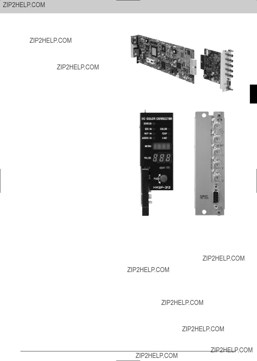
*HD signal color correction control; Master / Y, Pb, Pr / R, G, B / Video Gain, Chroma Gain, Hue, Set up / Gamma / White/Black Clip, Support for SMPTE292M formats:
1035/60i, 59.94i, 1080/60i, 59.94i, 50i, 1080/30PsF, 29.976PsF, 25PsF, 24PsF, 23.976PsF, 720/60P, 59.94P *Enhancer control *Active line conversions between 1035 and 1080 *Format conversion between 1080 and 720P *Audio delay function; Maximum two audio frames *HD SDI active
The
Applicable Models
Supplied Accessories
Operation manual (1)
Installtion manual (1)
Slot number label (1)
Interface Processor SP Series
57

Interface Processor SP Series
Interface Processor SP Series
Specifications
Inputs/outputs
Digital video signal input:
HD SDI IN connector (BNC type) (1) HD component serial digital signal conforming to SMPTE291M/292M/299M, 1.4835 or 1.485 Gb/s
Input impedance: 75 ?? , unbalanced
Input return loss:
15 dB or more (5 MHz to 1.485 GHz) Transmission loss:
20 dB or less (at 742.5 MHz) Cable length:
100 m max. (when using a
HD SDI ACTIVE THROUGH OUT connector (BNC type) (1) Output level:
800 m
75 ?? , unbalanced Output return loss:
15 dB or more (5 MHz to 1.485 GHz) Reference inputs:
Supplied through the REF IN connectors on the
REF IN connectors (BNC type) (2) Black Burst or
Digital signal outputs:
HD SDI OUT connectors (BNC type) (3) HD serial digital signal conforming to SMPTE291M/292M/299M, 1.4835 or 1.485 Gb/s
Output level:
800 m
75 ?? , unbalanced Output return loss:
15 dB or more (5 MHz to 1.485 GHz) Rise/fall time:
Less than 270 ps Alignment jitter:
Within 135 ps
Digital input/output system delay
Video:
1 frame/3H/L.T.10 ??
General
Power requirements:
+12 V DC: less than 1.5 A Power consumption:
Max. 18 W Operating temperature:
5 to 40 ??C (41 to 104 ??F) Storage temperature:
10 to 90 % (without condensation) Dimensions
Board (H x W): 112.2 x 388.3 mm
(4 1/2 x 15 3/8 inches) Connector panel (H x D x W): 130 mm x 152.5 x 38 mm
(5 1/8 x 6 1/8 x 1 1/2 inches)
Mass Board:
Approx 500 g (1 lb 2 oz) Connector panel:
Approx. 200 g (7 oz)
Service parts: Extension boards
Video Controller
58
Interface Processor SP Series
The
Features
The
Applicable Models
Supplied Accessories
Operation manual (1)
Installtion manual (1)
Slot number label (1)
Interface Processor SP Series
59

Interface Processor SP Series
Interface Processor SP Series
Specifications
Inputs/outputs
Digital signal input:
SDI IN connector (BNC type) (1),
NTSC composite or 525/625 component serial digital signal with embedded audio conforming to
Input impedance: 75 ?? , unbalanced
Input return loss:
15 dB or more (5 MHz to 270 MHz) Cable length:
More than 200 m (when using Belden 8281, Fujikura 5C2V or equivalent coaxial cable)
Analog signal input:
ANALOG VIDEO IN connector (BNC type) (1),
Video level: 1.0
Input impedance: 75 ?? , unbalanced
Reference inputs :
Supplied through the REF IN connectors on the
REF IN connectors (BNC type) (2) Black Burst or
Digital signal outputs:
HD SDI OUT connectors (BNC type) (3) HD component serial digital signal conforming to SMPTE291M/292M/299M, 1.4835 or 1.485 Gb/s
Output level:
800 m
75 ?? , unbalanced Output return loss:
15 dB or more (5 MHz to 1.485 GHz) Rise/fall time:
Less than 270 ps Alignment jitter:
Within 135 ps
Digital input/output system delay
Video:
1frame
0.6 to 1.6 frames (frame synchronizer)
General
Power requirement 12VDC; Less Than 1.8A
Power consumption Max; 21.6W
Operating temperature:
5 ??to 40 ??C (41 to 104 ??F) Storage temperature:
10 to 90% (no condensation) Dimensions
Board (H x W): 112.2 x 388.3 mm
(4 1/2 x 15 3/8 inches) Connector panel (H x D x W):
130 x 152.5 x 38 mm
(5 1/8 x 6 1/8 x 1 1/2 inches)
Mass Board:
Approx 600 g (1 lb 2 oz) Connector panel:
Approx. 200 g (7 oz)
Service parts: Extension boards
60

Interface Processor SP Series
The
Features
*Distribution of an SD or HD SDI signal
The
Applicable Models
Supplied Accessories
Installation Guide (1)
Installation Manual (1)
Interface Processor SP Series
61

Interface Processor SP Series
Interface Processor SP Series
Specifications
Inputs/outputs
Serial digital input:
SDI IN connector (BNC type) (1) Data transfer rate:
143 Mb/s to 1.485 Gb/s Input signal:
Scramble NRZI signal, 0.8 V
15 dB or more (5 MHz to 1.485 GHz) Cable length:
100 m (when a
Serial digital output:
SDI OUT connector (BNC type) (1) Data transfer rate:
143 Mb/s to 1.485 Gb/s
143 Mb/s, 177 Mb/s, 270 Mb/s, 360 Mb/s, 540 Mb/s, 1.485/1.001 Gb/s, 1.485 Gb/s
Output amplitude: 0.8
Rise/fall time: 270 ps or less
Output return loss:
15 dB or more (5 MHz to 1.485 GHz)
General
Power Requirements: +12 V dc: 0.42 A
(supplied from a
Operation temperature:
5 to 40 ??C (41 to 104 ??F) Storage temperature:
10 to 90% (No condensation) Dimensions
Board (H x W): 112.2 x 388.3 mm
(4 1/2 x 15 3/8 inches) Connector Panel (H x D x W):
130 x 152.5 x 19 mm
(5 1/8 x 6 1/8 x 3/4 inches)
Mass Board:
Approx. 200 g (7 oz) Connector Panel:
Approx. 155 g (5 oz)
Service parts: Maintenance manual
HD/SD SDI OUT 1
HD/SD SDI OUT 2
HD/SD SDI OUT 3
HD/SD SDI OUT 4
HD/SD SDI OUT 5
HD/SD SDI OUT 6
62

Interface Processor SP Series
The
Features
*Used with
The
Applicable Models
Supplied Accessories
Installation Guide (1)
Installation Manual (1)
Interface Processor SP Series
63
Interface Processor SP Series
Interface Processor SP Series
Specifications
Inputs/outputs
OPTICAL IN connector: SC/PC type (1)
Adaptive plug : SC/PC type plug (1)
Adaptive cable:
1310 nm single mode optical fiber Optical device:
Photo diode Laser wavelength:
1310 nm Input signal:
Scrambled NRZI Optical input level:
BNC Type (3) Data transfer rate:
143 Mb/s to 1.485 Gb/s Output amplitude:
0.8 V
270 ps or less Output return loss:
15 dB or more (5 MHz to 1.485 GHz)
General
Power requirements: + 12 V DC: 0. 37 A
(supplied from
Operating temperature:
5 to 40 ??C (41 to 104 ??F) Storage temperature:
10 to 90% (no condensation) Dimensions
Board (H x W): 112.2 x 388.3 mm
(4 1/2 x 15 3/8 inches) Connector Panel (H x D x W):
130 x 152.5 x 19 mm
(5 1/8 x 6 1/8 x 3/4 inches)
Mass Board:
Approx. 200 g (7 oz) Connector Panel:
Approx. 130 g (5 oz)
Service parts: Maintenance manual
HD/SD SDI OUT 1
HD/SD SDI OUT 3
64

Interface Processor SP Series
The
Features
*Used with
The
Applicable Models
Supplied Accessories
Installation Manual (1)
Installtion Guide (1)
Interface Processor SP Series
65

Interface Processor SP Series
Interface Processor SP Series
Specifications
Inputs/outputs
SDI IN connector: BNC type (1)
Data transfer rate:
143 Mb/s to 1.485 Gb/s Input signal:
Scrambled NRZI, 0.8 V
15 dB or more (5 MHz to 1.485 GHz) Input cable length:
100 m (when a
Active
Data transfer rate:
143 Mb/s to 1.485 Gb/s
143 Mb/s, 177 Mb/s, 270 Mb/s, 360 Mb/s, 540 Mb/s, 1.485/1.001 Gb/s, 1.485 Gb/s
Output amplitude: 0.8
Rise/fall time: 270 ps or less
Output return loss:
15 dB or more (5 MHz to 1.485 GHz) OPTICAL OUT connector:
SC/PC Type (1) Adaptive plug:
SC/PC Type Plug Adaptive cable:
1310 nm single mode optical fiber Optical device:
laser diode Laser wave length:
1310 nm
Optical output level:
General
Power Requirements: +12 V DC: 0.37 A
(supplied from
Operating temperature:
5 to 40 ??C (41 to 104 ??F) Storage temperature:
Board (H x W): 112.2 x 388.3 mm
(4 1/2 x 15 3/8 inches) Connector Panel (H x D x W):
130 x 152.5 x 19 mm
(5 1/8 x 6 1/8 x 3/4 inches)
Mass Board:
Approx. 200 g (7 oz) Connector Panel:
Approx. 130 g (5 oz)
Service parts: Maintenance manual
Interface Processor SP Series
The
Features
*Wide range of applications ??? Remotely controls the functions and monitors the status of the
Applicable Models
Note: An
Controller board is required.
Supplied Accessories
Operation manual (1)
Installation manual (1)
Rack mount kit (1)
Specifications
Control signal
DATA LAN:
EXT PANEL1:
General
Power requirements:
85 to 265 V AC, 47 to 63 Hz Power consumption:
5 V, 15 W Dimensions (H x D x W):
130 x 75 x 306 mm
(5 1/8 x 3 x 12 1/8 inches) Mass:
Approx. 1.5kg (3 lb 5 oz)
Service parts: Maintenance manual, AD code
Interface Processor SP Series
67
Interface Processor SP Series
Interface Processor SP Series
68
Interface Processor L Series
Interface Processor L Series
69

Processor L Series
Interface Processor L Series
The
Features
* Compact design of 2U height * Accepts up to 10 digital and analog video/audio function boards in any combination * Redundant power supply *
Rear Panel
Interface
Optional Accessories
Optional Boards
Operating temperature:
5 to 40 ??C (41 to 104 ??F) Storage temperature:
10 to 90% (No condensation) Dimensions (W x H x D)
440 x 88 x 353.2 mm
(17 3/8 x 3 1/2 x 14 inches) Mass:
Approx. 6.2 kg (13 lb 10.7 oz) (Excluding backup supply unit)
Status output port:
Backup power supply: Available
Maximum number of boards installed: 10
Service parts:
Optional Peripherals
Specifications
General
Power requirements:
AC 100 to 240 V, 50/60 Hz Power consumption:
Max. 130 VA Supply capability:
DC +5 V 13 A max. for the installed boards
70

Interface Processor L Series
The
Features
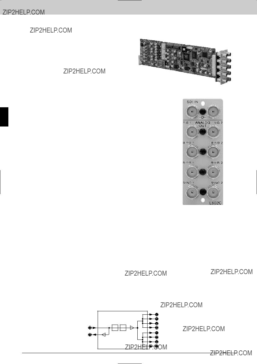
* Converts a 525/625 component analog video signal to a 525/625 component serial digital video signal *
The
Rear Panel
Operating humidity:
10 to 90% (no condensation) Dimensions
Board (H x D): 77 x 267 mm
(3 1/8 x 10 5/8 inches) Connector panel (W x H):
33 x 85 mm
(1 5/16 x 3 3/8 inches)
Mass Board:
Approx. 140 g (5 oz) Connector panel:
Approx. 120 g (4 oz)
Service parts: Extension board (Part
525/625
SDI OUT 1 COMPONENT
DIGITAL VIDEO
SDI OUT 2
SDI OUT 3
SDI OUT 4
Interface Processor L Series
71
Interface Processor L Series
The
Features
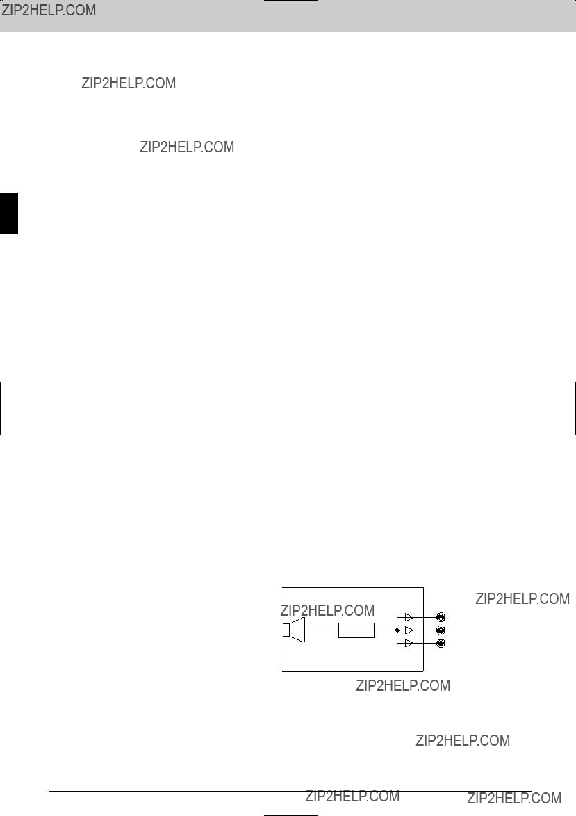
* Converts a 525/625 component serial digital signal to a 525/625 component analog signal *
The
Interface Processor L Series
Applicable Models
Supplied Accessories
Specifications
Inputs/outputs
Serial digital input:
SDI IN connector (BNC type) (1) 0.8
4:2:2 component serial digital signal Serial digital outputs:
(1)
0.8
4:2:2 component serial digital video signal Analog outputs:
ANALOG OUT Y/G,
Analog component video signals or RGB signals (selectable with
RGB signals:
R: 0.7
G: 0.7
B: 0.7
Defined with the color bar signal 100/0/100/0. YUV (CCIR) signals:
Y: 1.0
Defined with the color bar signal 100/0/100/0. YUV (Betacam 7.5% setup) signals:
Y: 1.0
Defined with the color bar signal 100/7.5/77/7.5.
YUV (Betacam 0% setup) signals:
Y: 1.0
Defined with the color bar signal 100/0/75/0.
Sync signal outputs:
SYNC connectors: BNC type (2) 2.0
Data transmission
Channel coding: Scrambled NRZI
Transmission speed: Input: 270 Mb/s
Amplitude:
0.8
200 m max. (when using a Belden 8281, Fujikura 5C2V or equivalent coaxial cable)
Digital input/output return loss:
15 dB or more (5 MHz to 270 MHz) Signal format:
4:2:2 component serial digital video signal conforming to SMPTE259M
Serial digital interface
Video characteristics
Sampling frequency:
Y: 13.5 MHz
10 bits Bandwidth:
Y: 5.75 MHz
20 ns or less
K factor (2T pulse): 1% or less
System delay: Approx. 3.7 ??s
EDH:
Conforms to SMPTE PR165
General
Power requirements: +5 V DC: 1.0 A
(Supplied from the
Rear Panel
Operating temperature:
5 to 40 ??C (41 to 104 ??F) Operating humidity:
10 to 90% (no condensation) Dimensions
Board (H x D): 77 x 267 mm
(3 1/8 x 10 5/8 inches) Connector panel (W x H):
33 x 85 mm
(1 5/16 x 3 3/8 inches)
Mass Board:
Approx. 140 g (5 oz) Connector panel:
Approx. 120 g (4 oz)
Service parts: Extension board (Part
525/625
COMPONENT
DIGITAL VIDEO
ACTIVE
Y/G OUT 1
SYNC OUT 1 Y/G OUT 2
SYNC OUT 2
525/625 COMPONENT
ANALOG VIDEO (R/G/B or
72

Interface Processor L Series
The
Features
* 525/625 component serial digital or NTSC/PAL composite serial digital video input * Eight equalized and
The
Applicable Models
Supplied Accessories
Rear Panel
Interface Processor L Series
73

Interface Processor L Series
Interface Processor L Series
Specifications
Inputs/outputs
Serial digital input:
SDI IN connector (BNC type) (1) Serial digital outputs:
SDI OUT connectors (BNC type) (8) 0.8
Data transmission
Channel coding: Scrambled NRZI
Transmission speed:
143 Mb/s (NTSC composite serial digital)
177 Mb/s (PAL composite serial digital)
270 Mb/s (525/625 component serial digital)
Amplitude:
0.8
200 m max. (when using a Belden 8281, Fujikura 5C2V or equivalent coaxial cable)
Digital input/output return loss:
NTSC/PAL composite or 525/625 component serial digital signal conforming to
General
Power requirements: +5 V DC: 0.3 A
(Supplied from the
Operating temperature:
5 to 40 ??C (41 to 104 ??F) Operating humidity:
10 to 90% (no condensation) Dimensions
Board (H x D): 77 x 267 mm
(10 5/8 x 3 1/8 inches) Connector panel (W x H):
33 x 85 mm
(1 5/16 x 3 3/8 inches)
Mass Board
Approx. 110 g (4 oz) Connector panel
Approx. 100 g (4 oz)
Service parts: Extension board (Part
NTSC/PAL COMPOSITE DIGITAL or 525/625 COMPONENT DIGITAL
SDI OUT x 8
74

Interface Processor L Series
The
Features
* Multiplexes four AES/EBU stereo pair signals into a 525/625 component or NTSC composite serial digital video signal * Up to 16 individual audio channels multiplexed by cascading two boards * One serial digital input with an active
The
Rear Panel
Connector panel (W x H): 33 x 85 mm
(1 5/16 x 3 3/8 inches)
Mass Board:
Approx. 130 g (5 oz) Connector panel:
Approx. 120 g (4 oz)
Service parts: Extension board (Part
Interface Processor L Series
75

Processor L Series
Interface Processor L Series
The
Features
* Demultiplexes two AES/EBU stereo from a 525/625 component or NTSC composite serial digital video signal * Up to 16 individual audio channels demultiplexed by cascading two boards * One serial digital input with an active
The
Interface
Applicable Models
Supplied Accessories
Specifications
Inputs/outputs
SDI
SDI input:
SDI IN connector (BNC type) (1)
4:2:2 component serial digital video signal or 4 fsc NTSC composite digital video signal conforming to SMPTE259M (selectable with
Input impedance: 75 ??
Cable length:
200 m max. (when using a Belden 8281, Fujikura 5C2V or equivalent coaxial cable)
SDI outputs:
SDI OUT connectors (BNC type) (4) Serial digital video signal of the same format as that to the input connector 0.8
Digital audio outputs
Digital audio signal outputs:
AES/EBU OUT connectors (BNC type) (4) 48 kHz/20 bits
AES/EBU digital audio signal, 1
Multiplex system:
Conforms to SMPTE 272M
EDH:
Conforms to SMPTE PR165
General
Power requirements: +5 V DC: 1.1 A
(Supplied from the
Operating temperature:
5 to 40 ??C (41 to 104 ??F) Operating humidity:
10 to 90% (no condensation)Rear Panel Dimensions
Board (H x D): 77 x 267 mm
(3 1/8 x 10 5/8 inches) Connector panel (W x H):
33 x 85 mm
(1 5/16 x 3 3/8 inches)
Mass Board:
Approx. 130 g (5 oz) Connector panel:
Approx. 120 g (4 oz)
Service parts: Extension board (Part
Maintenance manual
76

Interface Processor L Series
The
Features
*High performance frame/line synchronizer ??? 10
The
Applicable Models
Supplied Accessories
Installation manual (1)
Installaton guide (1)
Slot number label (1 set) (1)
Rear Panel
Interface Processor L Series
77
Interface Processor L Series
Interface Processor L Series
Specifications
Inputs/outputs
Video standard:
525/625, 4:2:2 component serial digital signal (SDI), conforming to
Serial digital input:
SDI IN connector (BNC type) (1) Digital input return loss:
15 dB or more (5 MHz to 270 MHz) Cable length:
200 m max. (with Belden 8281, Fujikura 5C2V or equivalent coaxial cable)
Serial digital outputs:
SDI OUT connector (BNC type) (4), 0.8
Digital output return loss:
15 dB or more (5 MHz to 270 MHz) Reference input:
REF IN connector (BNC type) (1) 0.3
Reference output:
Passive
GPI:
REMOTE connector
Memory: 4 fields
Phase adjustment range:
Line:
Clock:
Fine: more than 80 ns (continuously variable)
General
Power requirements: +5 V DC: 0.7 A
(Supplied from
Operating temperature:
5 to 40 ??C (41 to +104 ??F) Storage temperature:
10 to 90% (no condensation) Dimensions
Board (H x W): 77 x 267 mm
(3 1/8 x 10 3/4 inches) Connector panel (H x D x W):
130 x 152.5 x 38 mm
(5 1/8 x 6 1/8 x 1 1/2 inches)
Mass Board:
Approx. 130 g (5 oz) Connector panel:
Approx. 120 g (4 oz)
Service parts: Extension board (Part
78
Interface Processor L Series
The
Features
* Three 525/625 component or NTSC/PAL composite serial digital video inputs * Two equalized and
(at 540 Mb/s/360, 270, 177, 143 Mb/s with Belden 8281, Fujikura 5C2V or equivalent cable) * Accepts DVB/ASI signals * SDI input presence lamp
The
Processor L Series
Applicable Models
Supplied Accessories
Specifications
Inputs/outputs
Serial digital inputs:
SDI IN connectors (BNC type) (3) NTSC/PAL composite or 525/625 component serial digital signal conforming to
(Selectable by auto or manual settings) Input return loss:
15 dB or more (at 5 MHz to 540 MHz) Cable length:
143, 177, 270, 360 Mb/s: 200 m max.
540 Mb/s: 150 m max. (When using a Belden 8281, Fujikura 5C2V or equivalent coaxial cable)
Serial digital outputs:
SDI OUT connectors (BNC type) (6;3 for each channel)
0.8
15 dB or more (at 5 MHz to 540 MHz) Rise time/fall time:
0.5 to 0.75 ns (20% and 80% amplitude points)
Overshoot:
Less than 10%
Alignment jitter:
Less than 0.2
DC offset:
Less than 0 60.5 V
General
Power requirements:
+ 5 V DC: 0.7 A (supplied from the
Operating temperature:
5 to 40 ??C (41 to 104 ??C) Operating humidity:
10 to 90% (no condensation) Dimensions
Board (H x D): 77 x 267 mm
(3 1/8 x 10 5/8 inches) Connector panel (W x H):
33 x 85 mm
(1 5/16 x 3 3/8 inches)
Mass Board:
140 g (5 oz)Rear Panel Connector panel:
100 g (4 oz)
Service parts: Extension board (Part
Interface
79

Interface Processor L Series
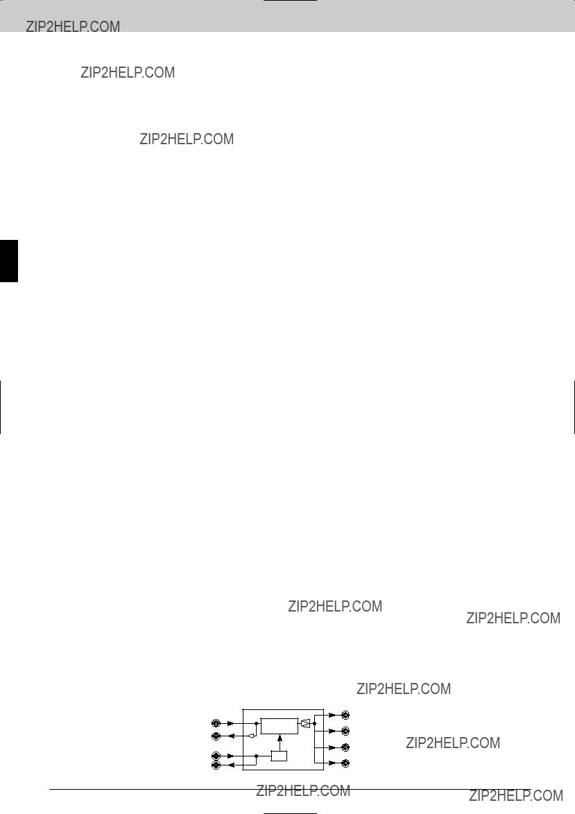
Interface Processor L Series
The
Features
* Two 525/625 component serial digital or NTSC/PAL composite serial digital video inputs * Four equalized and
The
80
Interface Processor L Series
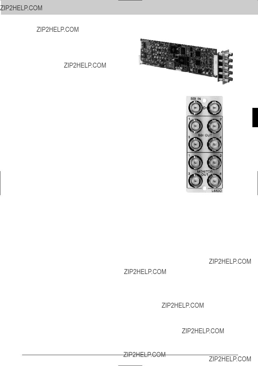
The
Features
* Distributes a 525/625 component serial digital input signal to four outputs * Analog video monitoring outputs (composite analog, Y/U/V or R/G/B component analog) * Active through output * Supports EDH
The
Applicable Models
Supplied Accessories
Rear Panel
Interface Processor L Series
81

Interface Processor L Series
Interface Processor L Series
Specifications
Inputs/outputs
Serial digital input:
SDI IN connector (BNC type) (1) 0.8
525/625 component serial digital signal conforming to
Serial digital outputs:
0.8
Serial digital video signal of the same format as that to the input connector SDI OUT connectors (BNC type) (4)
0.8
Serial digital video signal of the same format as that to the input connector
Analog outputs:
MONITOR OUT connectors (BNC type) (4) 4 NTSC/PAL composite analog video signals or 1 each R/G/B signals or 1 each Y/U/V signals and 1 NTSC/PAL composite analog video signals
RGB signals:
R: 0.7
G: 0.7
B: 0.7
YUV (CCIR level, 625 mode only) signals: Y: 1.0
Defined with the color bar signal 100/0/100/0
YUV (Betacam 7.5% setup, 525 mode only) signals:
Y: 1.0
Defined with the color bar signal 100/7.5/77/7.5
YUV (Betacam 0% setup, 525 mode only) signals:
Y: 1.0
Defined with the color bar signal 100/0/75/0 NTSC composite video (525 mode only) signals:
1.0
PAL composite video (625 mode only) signal: 1.0
Data transmission
Channel coding: Scrambled NRZI
Transmission speed: Input: 270 Mb/s
Amplitude:
0.8
Cable length:
200 m max. (When using a Belden 8281, Fujikura 5C2V or equivalent coaxial cable)
Digital input/output return loss:
15 dB or more (5 MHz to 270 MHz) Signal forma:
525/625 component serial digital signal conforming to
Video characteristics
Sampling frequency:
Y: 13.5 MHz
Composite signal: 27 MHz Digitization:
8 bits (Only for the composite signals, interpolating 8 bits to 10 bits.)
Bandwidth:
Y, R, G, B composite: 5 MHz
Y,
K factor (2T pulse): 1% or less
Y,
Composite signal: 54 dB or more (when the lamp signal is input)
DG:
2% or less DP:
2?? or less System delay:
Approx. 2.3 ms EDH:
Conforms to SMPTE RP165
General
Power requirements: +5 V DC: 1.0 A
(Supplied from the
Operating temperature:
5 to 40 ??C (41 to 104 ??F) Operating humidity:
10 to 90% (no condensation) Dimensions
Board (H x D): 77 x 267 mm
(10 5/8 x 3 1/8 inches) Connector panel (W x H):
33 x 85 mm
(1 5/16 x 3 3/8 inches)
Mass Board:
Approx. 150 g (5 oz) Connector panel:
Approx. 120 g (4 oz)
Service parts: Extension board (Part
525/625 COMPONENT SDI IN
ACTIVE
SDI OUT x 4
(FOR MONITORING)
COMPOSITE ANALOG VIDEO OUT x4 (NTSC/PAL)
or
Y/U/V + COMPOSITE ANALOG VIDEO OUT x 1 or
R/G/B + COMPOSITE ANALOG VIDEO OUT x 1
82

Interface Processor L Series
The
Features
* Two 525/625 component serial digital inputs with active
The
Processor L Series
Applicable Models
Supplied Accessories
Installation guide (1) Installtion manual (1)
Slot number label (1 set) (1)
Specifications
Inputs/outputs
Serial digital inputs:
SDI IN connectors (BNC type) (2) 525/625 component serial digital signal conforming to
Input return loss:
15 dB or more (at 5 MHz to 270 MHz) Cable length:
200 m max. (When using a Belden 8281, Fujikura 5C2V or equivalent coaxial cable)
Serial digital outputs:
Active
0.8
15 dB or more (at 5 MHz to 540 MHz) Rise time/fall time:
0.5 to 0.75 ns
(20% and 80% amplitude points) Overshoot:
Less than 10% Alignment jitter:
Less than 0.2
Less than 60.5 V
Analog outputs:
VIDEO OUT connectors (BNC type) (6; 3 for each channel)
NTSC: 1.0
PAL: 1.0
Analog Video Characteristics
Sampling frequency: 27.0 MHz
Resolution:
10 bits (conversion from 8 bits to 10 bits) Signal to noise ratio:
54 dB or more Frequency response:
60.5 dB DG/DP:
NTSC: Less than 2%/2??
PAL: Less than 2%/3.5?? Y/C delay:
Less than 620 ns
General
Power requirements:
+ 5 V DC: 1.0 A (supplied from the
Operating temperature:
5 to 40 ??C (41 to 104 F??) Operating humidity:
10 to 90% (no condensation) Dimensions
Board (H x D): 77 x 267 mm
(3 1/8 x 10 5/8 inches) Connector panel (W x H):
33 x 85 mm
(1 5/16 x 3 3/8 inches)
Rear Panel
Mass Board:
140 g (5 oz) Connector panel: 100 g (4 oz)
Service parts: Extension board (Part
Maintenance manual
Interface
83

Interface Processor L Series
Interface Processor L Series
The
Features
*High performance NTSC/PAL decoder to component SDI
??? 10
The
Applicable Models
Supplied Accessories
Installation guide (1)
Installation manual (1)
Slot number label (1 set) (1)
Rear Panel
84
Interface Processor L Series
Specifications
Inputs/outputs
Analog video input:
Analog IN connector (BNC type) (1), 1.0
Reference input:
REF IN connector (BNC type) (1), 0.3
75 ?? , black burst signal Analog video output:
Passive
1.0
Serial digital outputs:
SDI OUT Connectors (BNC type) (4), 0.8
Reference output:
Passive
Cable length:
200 m max. (with Belden 8281, Fujikura 5C2V or equivalent coaxial cable)
Channel coding: Scrambled NRZI
Digital output return loss:
15 dB or more (5 MHz to 270 MHz)
Video characteristics
Quantization: 10 bits
Sampling frequency Input:
28.636 MHz (NTSC input), 35.468 MHz (PAL input)
Output:
13.5 MHz (Y), 6.75 MHz
5.75 MHz (Y) K factor (2T pulse):
1% or less
58 dB or more (using Flat Field) Memory:
4 fields Processing delay:
74 ??s (NTSC)/137 ??s (PAL) Phase adjustment range
Line:
0.1 to 9 ??s, 37 ns step External REF mode:
75% color bars with 100% white
Connector panel (H x W): 85 x 33 mm
(3 3/8 x 1 5/16 inches)
Mass Board:
Approx. 170 g (6 oz) Connector panel:
Approx. 100 g (4 oz)
The total power consumption of the installed function boards should not exceed 13 A at 5 V
Interface Processor L Series

Interface Processor L Series
Interface Processor L Series
The
Features
*High performance NTSC/PAL encoder ??? 12
The
Applicable Models
Supplied Accessories
Installation guide (1)
Installation manual (1)
Slot number label (1 set) (1)
Rear Panel
86
Interface Processor L Series
Specifications
Inputs/outputs
Serial digital input:
SDI IN connector (BNC type) (1),
0.8
Reference input:
REF IN connector (BNC type) (1), 0.3
Digital input return loss:
15 dB or more (5 MHz to 270 MHz) Serial digital output:
Active
0.8
Analog video outputs:
ANALOG OUT connectors (BNC type) (4),
NTSC/PAL composite analog video signal, 1.0
Reference output:
Passive
0.3
Digital output return loss:
15 dB or more (5 MHz to 270 MHz) Cable length:
200 m max. (with Belden 8281, Fujikura 5C2V or equivalent coaxial cable)
Channel coding: Scrambled NRZI
Video characteristics
Sampling frequency: 27 MHz
Quantization: 10 bits Band width: 5.75 MHz
DG:
1% or less DP:
Within 1 ??
K factor (2T pulse): 1% or less
60 dB or more (using Flat Field) Y/C delay:
610 ns or less Processing delay:
4 ??s (NTSC)/7.5 ?? (PAL) Phase adjustment range
Line:
0.1 to 8.5 ??s (NTSC), 0.1 to 7.0 ??s (PAL)
External REF mode:
General
Power requirement:
+5 V DC: 1.2 A (supplied from
Operating temperature:
5 to 40 ??C (41 to 104 ??F) Storage temperature:
Operating humidity:
10 to 90% (no condensation) Dimensions
Board (H x W): 77 x 267 mm
(3 1/8 x 10 3/4 inches) Connector panel (H x W):
33 x 85 mm
(3 3/8 x 1 5/16 inches)
Mass Board:
Approx. 150 g (5 oz) Connector panel:
Approx. 100 g (4 oz)
Service part: Maintenance manual
Interface Processor L Series
87

Interface Processor L Series
The
Features
* Single or dual distribution configuration (selectable with
The
Interface Processor L Series
Applicable Models
Supplied Accessories
Specifications
Input/output connectors
Audio inputs:
AES/EBU IN connectors (BNC type) (2), 75 ?? ,
unbalanced Audio outputs:
AES/EBU OUT connectors (BNC type) (8), 75 ?? ,
unbalanced
Input characteristics
Standard input level: 1 V
Sampling frequency:
48 kHz, 44.1 kHz, 32 kHz Input jitter margin:
25 ns or more Input return loss:
25 dB or more (0.1 MHz to 6 MHz) Cable length:
1000 m max.
(when using a Belden 8281 coaxial cable, Fujikura 5C2V or equivalents)
Output characteristics
Dimensions Board (H x D):
77 x 267 mm
(3 1/8 x 10 5/8 inches) Connector panel (W x H):
33 x 85 mm
(1 5/16 x 3 3/8 inches)
Mass Board:
Approx. 120 g (4 oz) Connector panel:
Approx. 120 g (4 oz)
Service parts: Extension board (Part
Rear Panel
Output signal level:
1 V
Within 6 50 mV Waveform rising/falling:
37 6 7 ns Output jitter:
Within 10 ns Output return loss:
25 dB or more (0.1 MHz to 6 MHz) System delay:
Approx. 150 ns (during
Interface Processor L Series
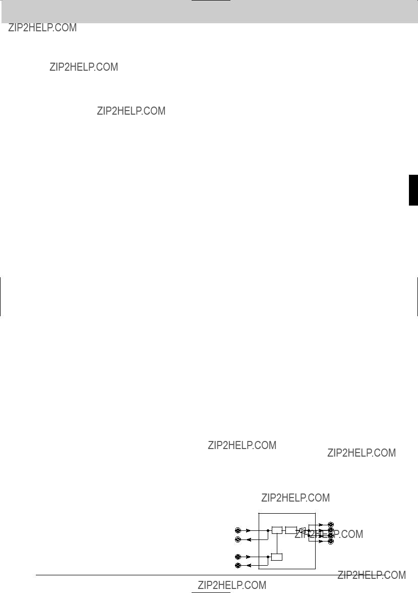
The
Features
* Distributes an NTSC/PAL composite analog input signal to eight outputs * Differential input * Passive
The
Applicable Models
Supplied Accessories
Rear Panel
Interface Processor L Series
89
Interface Processor L Series
Interface Processor L Series
Specifications
Inputs/outputs
Video input:
VIDEO IN connector (BNC type) (1) Video outputs:
VIDEO OUT connectors (BNC type) (8) 1
Video characteristics
Frequency response: 5 MHz
Input return loss:
40 dB or more (8 MHz or less) K factor:
1% or less DG:
1% or less DP:
1% or less
70 dB or more (using FLAT FIELD) Cable length:
300 m max. (When using a Belden 8281, Fujikura 5C2V or equivalent coaxial cable)
General
Power requirements:
+5 V DC: 250 mA (supplied from the
Operating temperature:
5 to 40 ??C (41 to 104 ??F) Operating humidity:
10 to 90% (no condensation) Dimensions
Board (H x D): 267 x 77 mm
(10 5/8 x 3 1/8 inches) Connector panel (W x H):
33 x 85 mm
(1 5/16 x 3 3/8 inches)
Mass Board:
Approx. 110 g (4 oz) Connector panel:
Approx. 110 g (4 oz)
Service parts: Extension board (Part
90
Interface Processor L Series
The
Features
*Regenerates black burst signals * NTSC composite analog input with passive
*SCH warning lamp *
The
Series
Applicable Models
Supplied Accessories
Specifications
Inputs/outputs
Video input:
VIDEO IN connectors (BNC type) (1) 0.286
Input return loss:
40 dB or more (at above 5 MHz) Analog output:
Passive
Black burst outputs:
BLACK BURST OUT connectors (BNC type) (6), conforming to
Output level:
SYNC: 0.286
BURST: 0.286
Less than 65?? Output return loss:
40 dB or more (above 5 MHz) H phasing:
Approx.
V phasing:
General
Mass Board:
140 g (5 oz) Connector panel: 100 g (4 oz)
Service parts: Extension board (Part
Rear Panel
Interface Processor L
Power requirements:
+ 5 V DC: 0.35 A (supplied from the
Operating temperature:
5 to 40 ??C (41 to 104 ??F) Operating humidity:
10 to 90% (no condensation) Dimensions
Board (H x D): 77 x 267 mm
(3 1/8 x 10 5/8 inches) Connector panel (W x H):
33 x 85 mm
(1 5/16 x 3 3/8 inches)
91
Interface Processor L Series
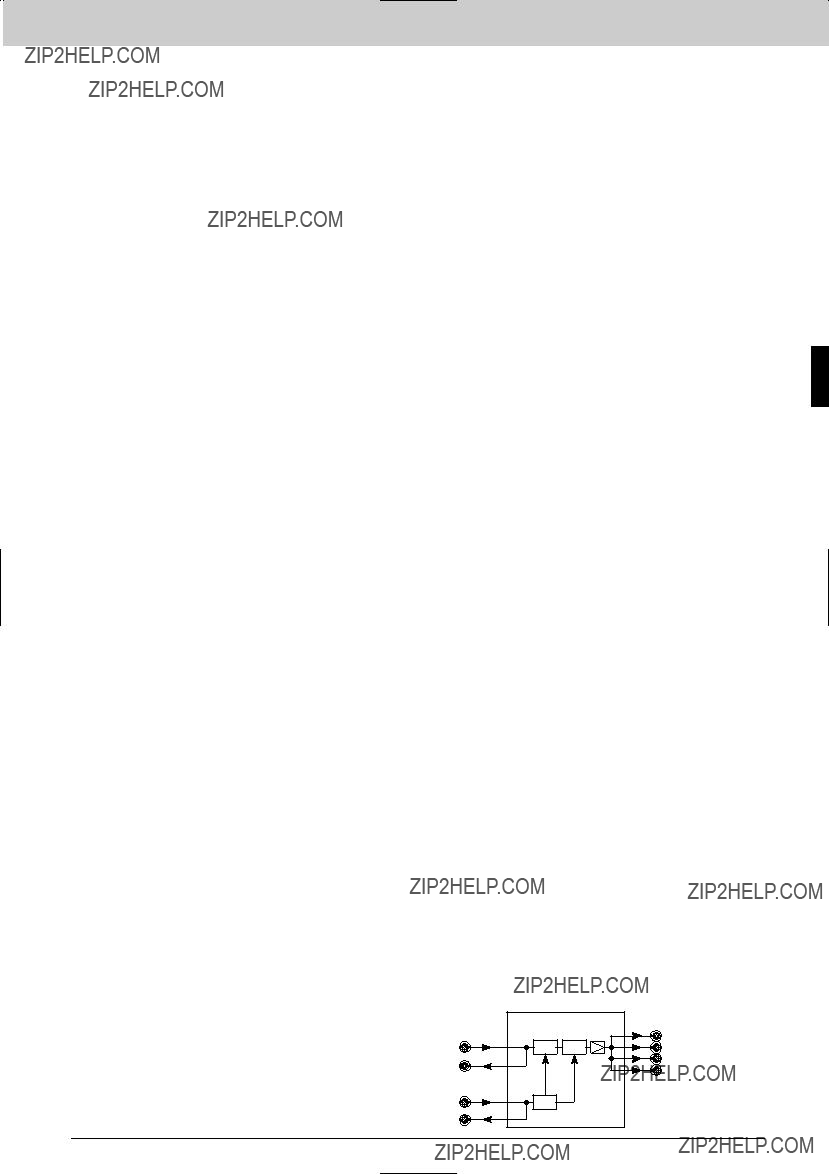
The
Features
*Distributes an NTSC or PAL analog signal, with a delay function * Adjustable delay range, 50 ns to 1430 ns * Eight distribution outputs * Passive
*Output level adjustment range: 62 dB *
The
Interface Processor L Series
Applicable Models
Supplied Accessories
Specifications
Inputs/outputs
Video input:
VIDEO IN connector (BNC type) (1), 1
Input return loss:
40 dB or more (at under 5 MHz) Video outputs:
VIDEO OUT connectors (BNC type) (8) Passive
Cable length:
300 m max. (When using a Belden 8281, Fujikura 5C2V or equivalent coaxial cable)
Output return loss:
40 dB or more (at above 5 MHz) System delay:
Approx. 50 to 1430 ns 350 ns x 3 STEP
75 ns x 5 STEP
15 ns x 5 STEP
FINE adjustment: 15 ns
Analog Video Characteristics
Signal to noise ratio:
70 dB or more (10 kHz to 6 MHz) Frequency response:
Less than
Less than 0.5%/0.5?? K factor:
0.5% or less
General
Power requirements:
+ 5 V DC: 0.6 A (supplied from the
Operating temperature:
5 to 40 ??C (41 to 104 ??F) Operating humidity:
10 to 90% (no condensation)
Dimensions Board (H x D):
77 x 267 mm
(3 1/8 x 10 5/8 inches) Connector panel (W x H):
33 x 85 mm
(1 5/16 x 3 3/8 inches)
Mass Board:
170 g (6 oz) Connector panel: 120 g (4 oz)
Service parts: Extension board (Part
Rear Panel
92
Interface Processor L Series
The
Features
* Converts two stereo analog audio signals to two AES/EBU digital audio signals * 24 bits conversion at 48 kHz sampling frequency * The signals carried by the two AES/EBU outputs can be interchanged * Sync input accepts an NTSC/PAL/HD video or 48 kHz word clock signal (manual selection with
The
Applicable Models
Supplied Accessories
Phoenix type
Rear Panel
Interface Processor L Series
93

Interface Processor L Series
Interface Processor L Series
Specifications
Inputs/outputs
Analog audio inputs:
AUDIO IN connectors (Phoenix type
(2; 4 channels
+ 4 dBm (600 ?? /20 k?? selectable, balanced)
Reference input:
REF VIDEO/WORD CLOCK IN connector
(BNC type) (1) Video input:
0.3
Word sync:
0.5 to 5.0
40 dB or more (at 5 MHz, 75 ?? terminated)
AES/EBU audio outputs:
AES/EBU OUT connectors (BNC type) (2; 1 for each stereo pair)
1.0
25 dB or more (at 0.1 MHz to 6.0 MHz) Rise time/fall time:
30 to 44 ns Alignment jitter:
Less than 620
Less than 0 650 mV Reference output:
Passive
(BNC type) (1) Word sync output:
1.0
Video characteristics
Sampling frequency: 48 kHz
Resolution: 24 bits Head room:
20 dB (at +4 dBm) Channel coding:
AES/EBU format Frequency response:
Within
Less than 0.02% Signal to noise ratio:
103 dB or more Crosstalk:
Less than
More than 80 dB (at 60 Hz) Phase difference between channels:
Less than 4?? (at 1 kHz) Encoding delay:
Approx. 0.9 ms
Dimensions Board (H x D):
77 x 267 mm
(3 1/8 x 10 5/8 inches) Connector panel (W x H):
33 x 85 mm
(1 5/16 x 3 3/8 inches)
Mass Board:
160 g (6 oz) Connector panel: 110 g (4 oz)
Service parts: Extension board (Part
General
Power requirements:
+ 5 V DC: 1.1 A (supplied from the
Operating temperature:
5 to 40 ??C (41 to 104 ??F) Operating humidity:
10 to 90% (no condensation)
AUDIO IN
AUDIO IN
AUDIO IN
AUDIO IN
REF IN
or WORD CLOCK OUT
AES/EBU OUT 1
AES/EBU OUT 2
94
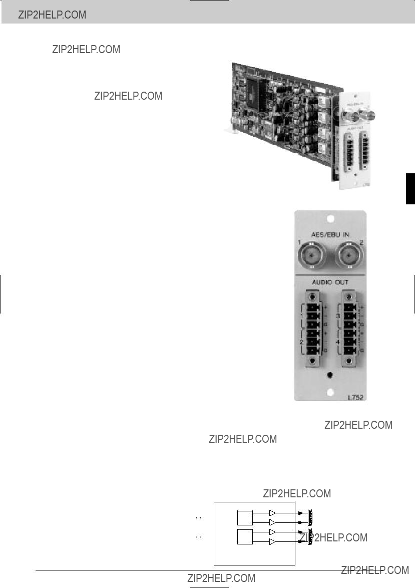
Interface Processor L Series
The
Features
*Converts AES/EBU digital signals to analog audio signals * 24 bits conversion at 48 kHz sampling frequency
*Dual AES/EBU inputs are each output as two analog signals *
The
Applicable Models
Supplied Accessories
Phoenix type
Specifications
Inputs/outputs
AES/EBU digital audio inputs:
AES/EBU IN connectors (BNC type) (2), 75 ??
Cable length:
1200 m max. (1
25 dB or more (at 0.1 MHz to 6 MHz) Analog audio outputs:
AUDIO OUT connectors (Phoenix type
(2; 4 channels
+4 dBm
Maximum output level:
+24 dBm (at 0 dB FS input) Output impedance:
Approx. 22 ??
Video characteristics
Sampling frequency: 48 kHz
Resolution: 24 bits Head room:
20 dB (at +4 dBm) Channel coding:
AES/EBU format Frequency response:
Within 20 Hz to 20 kHz,
Less than 0.02% Signal to noise ratio:
95 dB or more Crosstalk:
Less than
Less than 4?? (at 1 kHz) Decoding delay:
Approx. 0.7 ms
General
Power requirements:
+5 V DC: 1.3 A (supplied from the
Operating temperature:
5 to 40 ??C (41 to 104 ??F) Operating humidity:
10 to 90% (no condensation) Dimensions
Board (H x D): 77 x 267 mm
(3 1/8 x 10 5/8 inches) Connector panel (W x H):
33 x 85 mm
(1 5/16 x 3 3/8 inches)
Mass Board:
180 g (6 oz) Connector panel: 90 g (3 oz)
Service parts: Extension board (Part
AES/EBU IN 1 
 DAC
DAC
AES/EBU IN 2 
 DAC
DAC
Interface Processor L Series
Rear Panel
ANALOG AUDIO OUT
ANALOG AUDIO OUT
ANALOG AUDIO OUT
ANALOG AUDIO OUT
95

Interface Processor L Series
The
Features
* Single or dual distribution configuration (selectable with
The
Interface Processor L Series
Applicable Models
Supplied Accessories
Phoenix type
Specifications
Inputs/outputs
Inputs/outputs (selectable with
Stereo:
1 input/4 outputs Monaural:
1 input/8 outputs
Input impedance (selectable with
600 ?? /20 k??
Standard input/output level: +4 dBm
Maximum input level: +28 dBm
Maximum output level: +24 dBm (600 ?? load)
CMRR:
80 dB or more (at 60 Hz) Frequency response:
60.1 dB
(20 Hz to 20 kHz, at 1 kHz standard, standard level)
Input/output gain settings:
62 dB Distortion:
0.01% or less
(20 Hz to 20 kHz, at +24 dBm output, with 0 dB gain)
115 dB or more (at +24 dBm output, 30 kHz LPF)
Crosstalk:
(20 Hz to 20 kHz at +24 dBm input/output, each channel)
General
Power requirements: +5 V DC: 1.2 A
(Supplied from the
Operating temperature:
5 to 40 ??C (41 to 104 ??F) Operating humidity:
10 to 90% (no condensation) Dimensions
Board (H x D): 77 x 267 mm
(3 1/8 x 10 5/8 inches)
Connector panel (W x H):Rear Panel 33 x 85 mm
(1 5/16 x 3 3/8 inches)
Mass Board:
Approx. 180 g (6 oz) Connector panel:
Approx. 70 g (2 oz)
Service parts: Extension board (Part
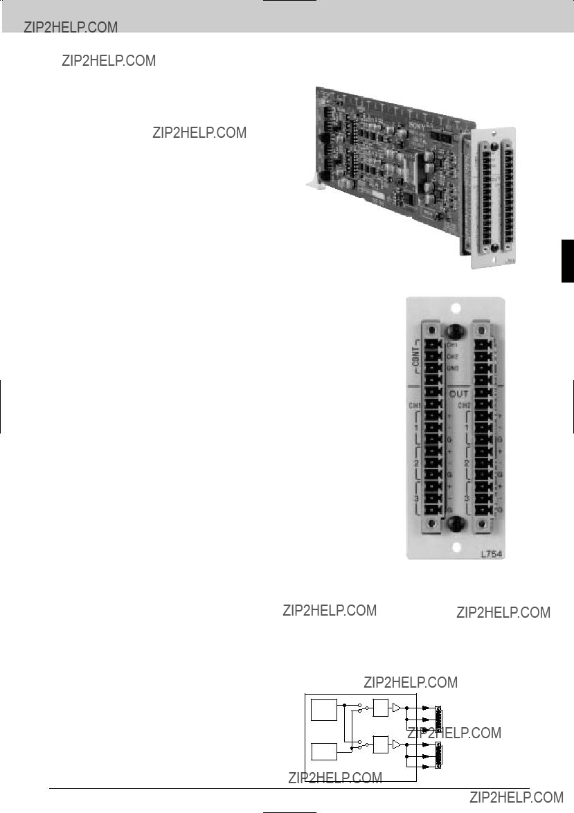
Interface Processor L Series
The
Features
* Provides two channels of test signals * Independent frequency setting of both signals to either 440 Hz or 1 kHz (440 Hz can be changed to 400 Hz with
SELECTABLE: 0/+4/+8 dBm 60.1 dB VARIABLE:
The
Applicable Models
Supplied Accessories
Phoenix type
(1)
Specifications
Inputs/outputs
Audio outputs (including remote) OUT and CONT connectors:
(Phoenix type
(6 channels - 3 stereo pair and 1 GPI)
Video characteristics
Output frequency:
400 Hz/440 Hz/1 kHz 610% Distortion:
Less than 0.01% Output level:
FIX: 0/+4/+8 dBm 60.1 dB (600 ?? loaded)
VARIABLE:
General
Power requirements:
+ 5 V DC: 0.5 A (supplied from the
Operating temperature:
5 to 40 ??C (41 to 104 ??F) Operating humidity:
10 to 90% (no condensation) Dimensions
Board (H x D): 77 x 267 mm
(3 1/8 x 10 5/8 inches) Connector panel (W x H):
33 x 85 mm
(1 5/16 x 3 3/8 inches)
Mass Board:
140 g (5 oz) Connector panel: 100 g (4 oz)
Service parts: Extension board (Part
Maintenance manual
Rear Panel
Interface Processor L Series
97

Interface Processor L Series
Interface Processor L Series
The
Features
* Two inputs * Four distribution outputs from each input * Switchable to a single input, eight output configuration * Equalization for up to 500 m cable (Belden 8281, Fujikura 5C2V or equivalent cable)
The
Applicable Models
Supplied Accessories
Operation manual (1)
Installation manual (1)
Slot number label (1)
Specifications
Inputs/outputs
A, B inputs:
IN connectors (BNC type) (2)
A, B output:
OUT connectors (BNC type) (8; 4 for each channel)
500 m max. (When using a Belden 8281, Fujikura 5C2V or equivalent coaxial cable)
General
Power requirements:
+5 V DC: 0.55 A (supplied from the
Operating temperature:
5 to 40 ??C (41 to 104 ??F) Operating humidity:
10 to 90% (no condensation) Dimensions
Board (H x D): 77 x 267 mm
(3 1/8 x 10 5/8 inches) Connector panel (W x H):
33 x 85 mm
(1 5/16 x 3 3/8 inches)
Mass
Board:
Approx. 100 g (4 oz)S-BUS
Connector panel: Approx. 100 g (4 oz)
Rear Panel
98
Interface Processor D Series
HDTV
Interface Processor D Series
99

Interface Processor D Series
Interface Processor D Series
HKPF Series boards provide a range of audio and video signal processing and distribution functions for HDTV signals. The
Features
* Accommodates and powers four function boards * Accepts all Sony HKPF boards * Redundant power supply option
Operation manual (1)
Installation manual (1)
Optional Accessories
Optional Boards
Optional Software
Specifications
Output
STATUS OUT:
General
Power requirements:
100 to 240 V AC, 50/60 Hz Power consumption:
1.8 to 0.9 A
Maximum power supply capacity: +5 V DC: max. 8 A
For installed boards
5 to 40 ??C (41 to 104 ??F) Storage temperature:
10 to 90% Dimensions (W x H x D)
424 x 132 x 428 mm
(16 3/4 x 5 1/4 x 16 7/8 inches) Mass:
Approx. 8 kg (17 lb 10 oz)
(not including the optional boards)
The total power consumption of the four installed function boards should not exceed 8 at 5 V and 8 at
100

Interface Processor D Series
HKPF Series boards provide a range of audio and video signal processing and distribution functions for HDTV signals. The
Features
*Houses up to 14 HKPF series modules *Power supply capacity increase to 31A maximum for +5V DC *Standard
Supplied Accessories
Operation Manual (1)
Installation Manual (1)
Optional Boards
Board
Board
Board
Board
Optional Software
Software
Optional Peripherals
Specifications
Outputs
STATUS OUT:
General
Power requirements:
100 to 240 V AC, 50/60Hz Power consumption:
5.0 to 2.0 A
Power supply capacity
+5 V DC: 31 A max.,
Operating temperature:
5 to 40 ??C (41 to +104 ??F) Performance guaranteed temperature:
5 to 40 ??C (41 to 104 ??F) Storage temperature:
10 to 90% (No Condensation) Dimensions (W x H x D):
424 x 310 x 460 mm
(16 3/4 x 12 1/4 x 18 1/8 inches) Mass:
Approx. 18 kg (39 lb 11 oz)
(Not including the optional boards)
Rear Panel
Interface Processor D Series
101

Interface Processor D Series
The
Features
* Converts an HD component analog signal to an HD component serial digital signal * Supports ISR
The HKPF Series function boards install in the
Interface Processor D Series
Applicable Models
Specifications
Inputs/outputs
Video inputs:
ANALOG IN Y/G, PB /B, and PR /R connectors (BNC type) (1 each) HD component analog video signals
(SMPTE240M/274M (59.94 or 60.00 Hz) standard) 75 ??
Video outputs:
DIGITAL OUT 1, 2, 3, and 4 connectors (BNC) (1 each)
HD component serial digital video signal conforming to SMPTE292M, 1.5 Gb/s (BTA
Output level:
0.8
75 ?? , unbalanced Return loss:
15 dB or more (5 to 750 MHz)
10 dB or more (750 MHz to 1.5 GHz) Rise/fall time:
270 ps or less, 20% to 80% Jitter:
270 ps or less Data rate:
1.4835 GHz or 1.485 GHz Delay time:
1500 ns or less ISR output information
Status messages: 1 item
Setup messages: 3 items
General
Power requirements:
+5.0 V DC: 1.3 A,
Power consumption: Approx. 11 W
Operating temperature:
5 to 40 ??C (41 to 104 ??F) Dimensions
Board (H x W): 194 x 310 mm
(7 3/4 x 12 1/4 inches) Connector panel (H x D x W):
218 x 98 x 25 mm
(8 5/8 x 3 7/8 x 1 inches)
Mass Board:
Approx. 700 g (1 lb 8 oz) Connector panel:
Approx. 200 g (7 oz)
102

Interface Processor D Series
The
Features
* Converts an HD component serial digital signal to an HD component analog signal * Supports ISR
The HKPF Series function boards install in the
Applicable Models
Specifications
Inputs/outputs
Video input:
DIGITAL IN connector (BNC type) (1) HD component serial digital video signal conforming to SMPTE292M, 1.5 Gb/s (BTA
Input impedance: 75 ?? , unbalanced
Return loss:
15 dB minimum (5 to 750 MHz)
10 dB minimum (750 MHz to 1.5 GHz) Cable length:
100 m max. (when using
Data rate:
1.4835 GHz or 1.485 GHz Video outputs:
ANALOG OUT Y/G, PB/B, and PR/R connectors (BNC type) (2 sets)
HD component analog video signal (SMPTE240M/274M (59.94 or 60.00 Hz) standard)
Output impedance: 75 ?? , unbalanced
Output level:
1.0
0.7
60.3dB (60 Hz to 20 MHz)
60.7dB (20 to 30 MHz) Sync signal:
ANALOG OUT SYNC connector (BNC type) (1)
Conforming to SMPTE240M/274M (59.94 or 60.00 Hz) standard.
Impedance:
75 ?? , unbalanced Level:
0.6
Delay time:
1000 ns or less
ISR output information:
Status messages: 2 items
Setup messages: 3 items
General
Power requirements:
+5.0 V DC: 1.4 A,
Power consumption: Approx. 10 W
Operating temperature:
5 to 40 ??C (41 to 104 ??F) Dimensions
Board (H x W): 194 x 310 mm
(7 3/4 x 12 1/4 inches) Connector panel (H x D x W):
218 x 98 x 25 mm
(8 5/8 x 3 7/8 x 1 inches)
Mass Board:
Approx. 700 g (1 lb 8 oz) Connector panel:
Approx. 200 g (7 oz)
Rear Panel
HD COMPONENT ANALOG
VIDEO OUTPUT G / B / R
or
Y / PB / PR
HD SERIAL DIGITAL
VIDEO INPUT
D/A
HD COMPONENT ANALOG
VIDEO OUTPUT G / B / R
or
Y / PB / PR
Interface Processor D Series
HD ANALOG SYNC OUTPUT
103

Interface Processor D Series
The
Features
* Accepts an SMPTE291M/292M/299M format input signal * Automatic equalization for input cable lengths of up to 100 m * Six distribution outputs * Support SMPTE292M formats * 1035(1125)/60i, 59.94i * 1080(1125)/60i, 59.94i, 50i * 1080(1125)/30PsF, 29.976PsF, 25PsF, 24PsF, 23.976PsF * 720(750)/60P, 59.94P * Auto selection of SMPTE292M video formats * Format indication on the front panel * Status output
The HKPF Series function boards install in the
Interface Processor D Series
Applicable Models
Specifications
Inputs/outputs
Digital signal input:
DIGITAL IN connector (BNC type) (1) HD component serial digital signal conforming to SMPTE291M/292M/299M
Input impedance: 75 ?? , unbalanced
Input return loss:
15 dB or more (5 MHz to 1.485 GHz) Transmission loss:
20 dB or less (at 742.5 MHz) Cable length:
100 m max. (When using Fujikura
Digital signal outputs:
DIGITAL OUT connectors (BNC type)
(6)
HD component serial digital signals conforming to SMPTE291M/292M/299M
Output signal amplitude:
800 m
75 ?? , unbalanced Output return loss:
15 dB or more (5 MHz to 1.485 GHz) Jitter:
Within 673 ps (timing jitter) Within 135 ps (alignment jitter)
Digital input/output system delay: 900 ns or less
General
Power requirements:
+5 V DC: 1.4 A,
Power consumption: Approx. 14 W
Operating temperature:
5 to 40 ??C (41 to 104 ??F) Storage temperature:
Humidity:
10 to 90% (without condensation) Dimensions
Board (H x W): 194 x 310 mm
(7 3/4 x 12 1/4 inches) Connector panel (H x D x W):
218 x 98 x 25 mm
(8 5/8 x 3 7/8 x 1 inches)
Mass Board:
700 g (1 lb 8.7 oz) Connector panel:
300 g (11 oz)
Rear Panel
104
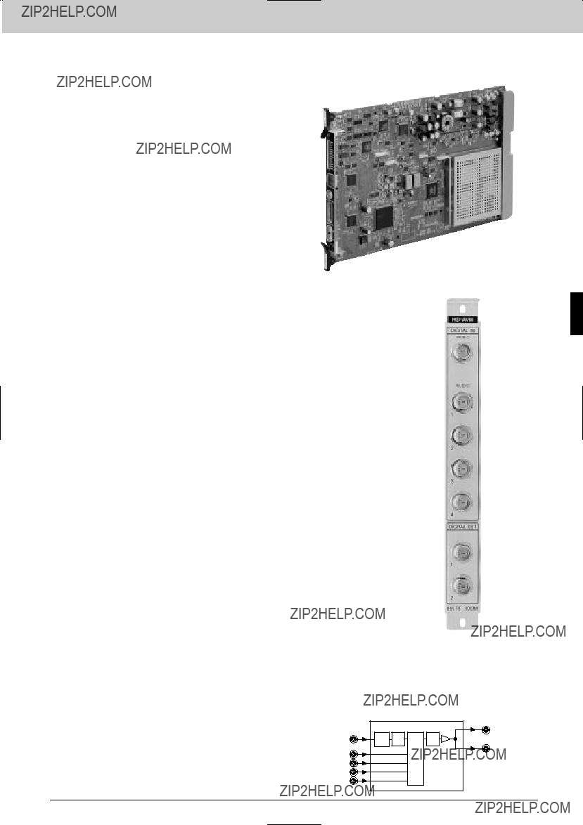
Interface Processor D Series
The
Features
*Multiplexes two AES/EBU signals with an HD component serial digital video signal * Selection of the audio group to be multiplexed * Audio delay function - one video frame * Support SMPTE292M formats * 1035(1125)/60i, 59.94i * 1080(1125)/60i, 59.94i, 50i *
1080(1125)/30PsF, 29.976PsF, 25PsF, 24PsF, 23.976PsF
*720(750)/60P, 59.94P * Auto selection of SMPTE292M video formats * Format indication on the front panel * Status output
The HKPF Series function boards install in the
Applicable Models
Specifications
Inputs/outputs
Digital video signal input:
DIGITAL IN VIDEO connector (BNC type) (1) HD component serial digital signal conforming to SMPTE291M/292M/299M
Input impedance: 75 ?? , unbalanced
Input return loss:
15 dB or more (5 MHz to 1.485 GHz) Transmission loss:
20 dB or less (at 742.5 MHz) Cable length:
100 m max. (When using a
Digital audio signal inputs:
DIGITAL IN AUDIO connectors (BNC type)
(4)
Digital signal outputs:
DIGITAL OUT connectors (BNC type) (2) HD component serial digital signal conforming to SMPTE291M/292M/299M
Output signal amplitude:
800 m
75 ?? , unbalanced Output return loss:
15 dB or more (5 MHz to 1.485 GHz) Jitter:
Within 673 ps (timing jitter) Within 135 ps (alignment jitter)
Audio delay
Setting method:
Delay range is set by the
Variable range:
0 to 157 samples Offset delay time:
0 or 1 frame
Digital input/output system delay
Video:
1.6 ??s (without
General
Power requirements:
+5 V DC: 1.6 A,
Power consumption: Approx. 15 W
Operating temperature:
5 to 40 ??C (41 to 104 ??F) Storage temperature:
10 to 90 % (without condensation) Dimensions:
Board (H x W): 194 x 310 mm
(7 3/4 x 12 1/4 inches) Connector panel (H x D x W):
218 x 98 x 25 mm
(8 5/8 x 3 7/8 x 1 inches)
Mass
Board:Rear Panel
700 g (1 lb 8.7 oz) Connector panel:
300 g (11 oz)
Interface Processor D Series
105

Interface Processor D Series
The
Features
*Demultiplexes and outputs the AES/EBU digital audio signals from an HD component serial digital video signal * Selection of the audio groups
*720(750)/60P, 59.94P * Auto selection of SMPTE292M video formats * Format indication on the front panel * Status output
The HKPF Series function boards install in the
Interface Processor D Series
Applicable Models
Specifications
Inputs/outputs
Digital video signal input:
DIGITAL IN connector (BNC type) (1) HD component serial digital signal conforming to SMPTE291M/292M/299M
Input impedance: 75 ?? , unbalanced
Input return loss:
15 dB or more (5 MHz to 1.485 GHz) Transmission loss:
20 dB or less (at 742.5 MHz) Cable length:
100 m max. (When using a
Digital audio signal outputs:
DIGITAL OUT AUDIO connectors (BNC type) (4)
?? ,
1
DIGITAL OUT VIDEO connectors (BNC type) (2)
HD component serial digital signal conforming to SMPTE291M/292M/299M
Output signal amplitud:
800 m
75 ?? , unbalanced Output return loss:
15 dB or more (5 MHz to 1.485 GHz) Jitter:
Within 673 ps (timing jitter) Within 135 ps (alignment jitter)
Digital input/output system delay
Video:
1.3 ??s (without
General
Power requirements:
+5 V DC: 1.5 A,
Power consumption: Approx. 15 W
Operating temperature:
5 to 40 ??C (41 to 104 ??F) Storage temperature:
10 to 90% (without condensation) Dimensions
Board (H x W): 194 x 310 mm
(7 3/4 x 12 1/4 inches) Connector panel (H x D x W):
218 x 98 x 25 mm
(8 5/8 x 3 7/8 x 1 inches)
Mass Board:
700 g (1 lb 8.7 oz) Connector panel:
300 g (11 oz)
Rear Panel
AES/EBU OUT 1
A/V 
 AES/EBU OUT 2
DE MUX 
 AES/EBU OUT 3
AES/EBU OUT 4
106
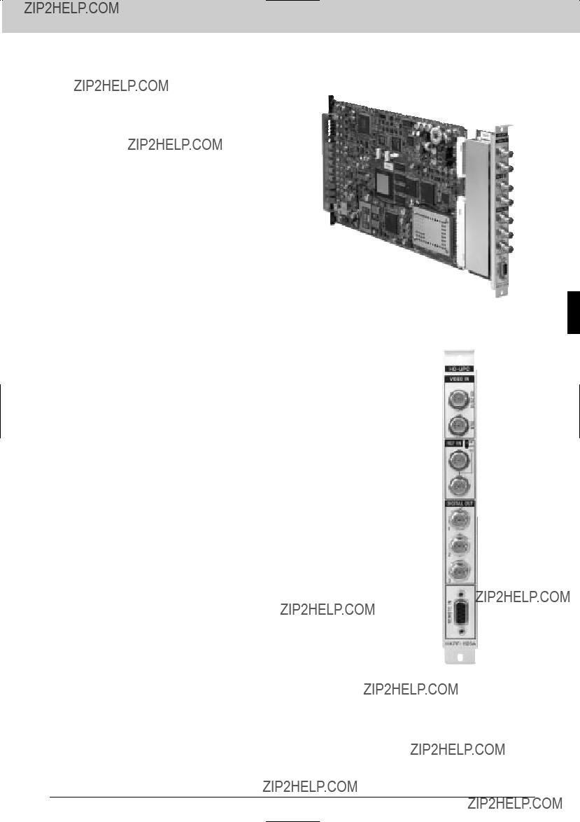
Interface Processor D Series
The
Features
The HKPF Series function boards install in the
Applicable Models
Supplied Accessories
Operation manual (1)
Installation manual (1)
Slot number label (1)
Interface Processor D Series
Rear Panel
107
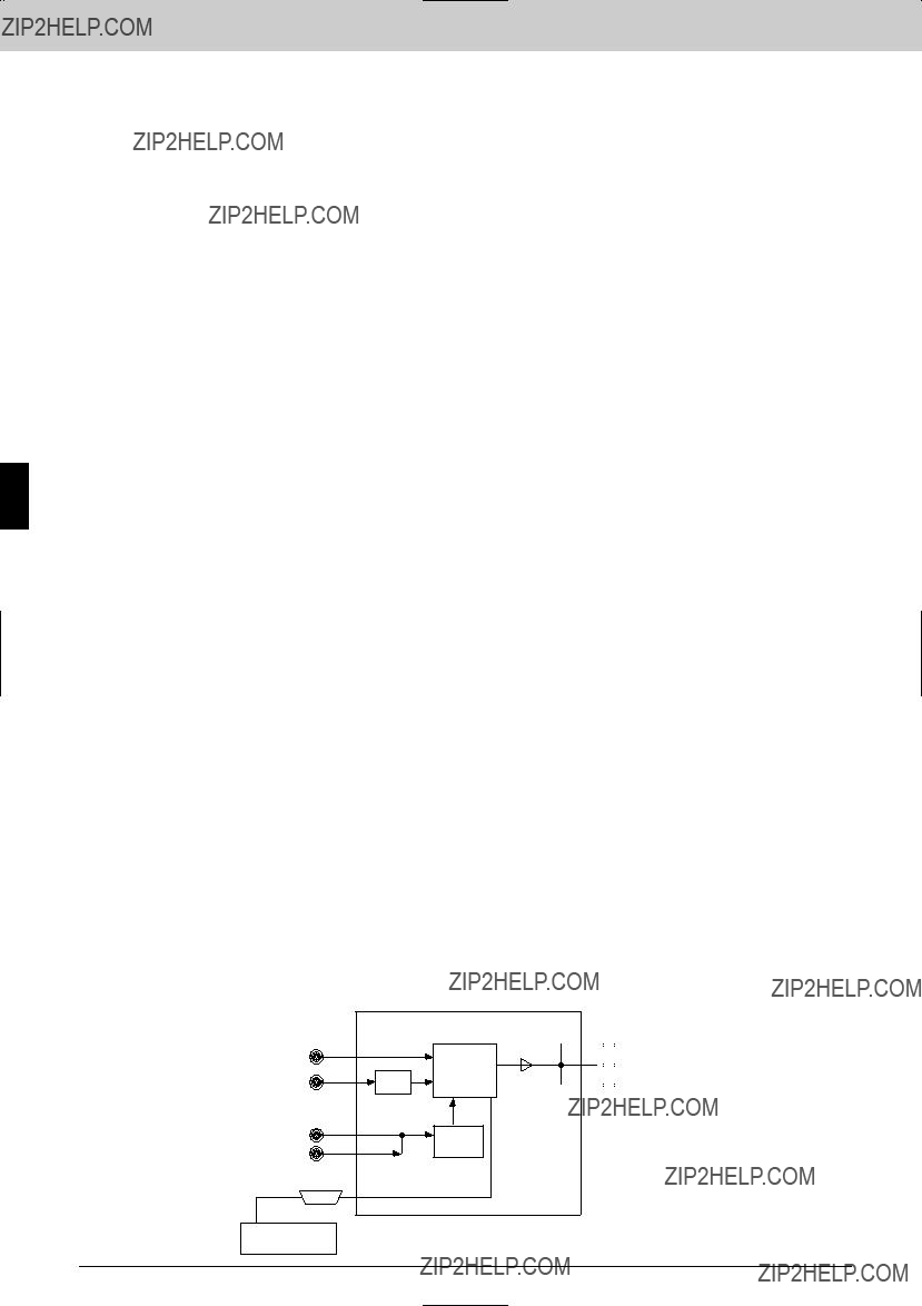
Interface Processor D Series
Interface Processor D Series
Specifications
Inputs/outputs
Digital signal input:
VIDEO IN SDI connector (BNC type) (1), NTSC composite or 525/625 component serial digital signal with embedded audio conforming to
Cable length:
200 m max. (With Belden 8281, Fujikura 5C2V or equivalent coaxial cable)
Input return loss:
15 dB or more (5 MHz to 270 MHz) Analog signal input:
VIDEO IN ANALOG connector (BNC type) (1),
1.0
REF IN connector (BNC type) (1), 1125
Digital signal outputs:
DIGITAL OUT 1,2,3 connector (BNC type) (3),
HD serial digital signal with embedded audio conforming to SMPTE292M, BTA
Output return loss:
15 dB or more (5 MHz to 1.5 GHz) Reference output:
With 75 ?? termination switch
General
Power requirements
+5 V DC:
(Supplied from a
5 to 40 ??C (41 to 104 ??F) Storage temperature
10 to 90% (no condensation) Dimensions
Board (H x W): 195 x 310 mm
(7 3/4 x 12 1/4 inches) Connector panel (H x W):
195 x 75 mm
(1 1/2 x 3 inches)
Mass Board:
Approx. 1.5 kg (3 lb 5 oz) Connector panel:
Approx. 200 g (7 oz)
Service Parts: Maintenance Manual, Extension Board
Video Controller

 HD SDI OUT 1 (1080i/1035i)


 HD SDI OUT 2

 HD SDI OUT 3
108
Interface Processor D Series
The
Features
* Downconverts an HD serial digital video signal to a SD component serial digital signal * Support 1080 (1035) i to 485i at 59.94 Hz and 1080i to 576i at 50 Hz conversion * Output signal aspect ratio selectable: squeeze, edge crop, semi letter box (13:9, 14:9) and letter box (16:9) * Minimum delay/frame delay selectable * Remote control from
The HKPF Series function boards install in the
Applicable Models
Specifications
Inputs/outputs
Digital video signal input:
DIGITAL IN connector (BNC type) (1) HD component serial digital video signal conforming to SMPTE292M, 1.5 Gb/s (BTA
Input impedance: 75 ?? , unbalanced
Input return loss:
15 dB minimum (5 to 750 MHz)
15 dB minimum (750 MHz to 1.5 GHz) Cable length:
100 m max. (When using a
Data rate:
1.4835 GHz/1.485 GHz Remote control signals:
REMOTE IN connector
Digital video outputs:
DIGITAL OUT 1, 2, 3, and 4 (BNC type) (1 each)
(switchable between Y/PB /PR and GBR)
Supported formats (selectable): 525/625 4:2:2
Three selectable modes (squeeze, edge crop, and letter box)
Adjustable delay range: Minimum Delay Mode 525:42 H
Adjustable parameters:
Detail gain, detail frequency,
level depend., crispness, H/V ratio, limit level, gamma
General
Power supply:
+5.0 V DC: 2.0 A,
Power consumption: Approx. 15 W
Operating temperature:
5 to 40 ??C (41 to 104 ??F) Dimensions:
Board (H x W): 194 x 310 mm
(7 3/4 x 12 1/4 inches) Connector panel (H x D x W):
218 x 98 x 25 mm
(8 5/8 x 3 7/8 x 1 inches)
Mass Board:
Approx. 1500 g (1 lb 8 oz) Connector panel:
Approx. 200 g (7 oz)
IN CASE OF 4:4:4
Video Controller
 LINK A
 LINK B
Interface Processor D Series
109

Interface Processor D Series
The
Features
* Downconverts an HD serial digital video signal to a SD component serial digital signal * Support 1080 (1035) i to 485i at 59.94 Hz and 1080i to 576i at 50 Hz conversion * Output signal aspect ratio selectable: squeeze, edge crop, semi letter box (13:9, 14:9) and letter box (16:9) * Minimum delay/frame delay selectable * Remote control from
The HKPF Series function boards install in the
Interface Processor D Series
Applicable Models
Specifications
Inputs/outputs
Digital video signal input:
DIGITAL IN connector (BNC type) (1) HD component serial digital video signal conforming to SMPTE292M, 1.5 Gb/s (BTA
Input impedance: 75 ?? , unbalanced
Input return loss:
15 dB minimum (5 to 750 MHz)
15 dB minimum (750 MHz to 1.5 GHz) Cable length:
100 m max. (When using a
Data rate:
1.4835 GHz/1.485 GHz Remote control signals:
REMOTE IN connector
Digital video outputs:
DIGITAL OUT 1, 2, 3, and 4 (BNC type) (1 each)
(switchable between Y/PB /PR and GBR)
Supported formats (selectable): 525/625 4:2:2
Three selectable modes (squeeze, edge crop, and letter box)
Adjustable delay range: Minimum Delay Mode 525:42 H
Adjustable parameters:
Detail gain, detail frequency,
level depend., crispness, H/V ratio, limit level, gamma
General
Power supply:
+5.0 V DC: 2.0 A,
Power consumption: Approx. 15 W
Operating temperature:
5 to 40 ??C (41 to 104 ??F) Dimensions:
Board (H x W): 194 x 310 mm
(7 3/4 x 12 1/4 inches) Connector panel (H x D x W):
218 x 98 x 25 mm
(8 5/8 x 3 7/8 x 1 inches)
Mass Board:
Approx. 1500 g (1 lb 8 oz) Connector panel:
Approx. 200 g (7 oz)
IN CASE OF 4:4:4
Video Controller
 LINK A
 LINK B
110

Interface Processor D Series
The
Features
* Converts 270 Mb/s SDTI (conforming to SMPTE305M) into 1.5 Gb/s HD component serial digital * Video with eight channels of embedded audio signal *
The HKPF Series function boards install in the
Applicable Models
Supplied Accessories
Operation manual (1)
Maintenance manual (1)
Slot number label (1)
Interface Processor D Series
Rear Panel
111

Interface Processor D Series
Interface Processor D Series
Specifications
Inputs/outputs
Digital input:
SDTI IN (HDCAM) connector (BNC type)
(1)
HDCAM over SDTI signal conforming to SMPTE305M
Input impedance: 75 ?? , unbalanced
Input return loss:
15 dB or more (5 MHz to 270 MHz) Cable length:
SDTI: 200 m max. (When using a Belden 8281, Fujikura 5C2V or equivalent coaxial cable)
Active through output: 75 ?? , unbalanced
SYNC signal input:
REF IN connector (BNC type) (1) 1125 or 525 SYNC signal
Input impedance: 75 ?? , unbalanced
Digital signal outputs:
DIGITAL OUT connectors (BNC type) (3) HD serial digital signal conforming to SMPTE292M (BTA
Output signal amplitude:
800 m
75 ?? , unbalanced Output return loss:
15 dB or more (5 MHz to 741.8 MHz)
10 dB or more (741.8 MHz to 1.484 GHz) Digital input/output system delay
REF lock:
2 frames (to reference) Minimum delay:
1.7 frames (to input) ISR output information
Status messages: 8 items
General
Power requirements:
+5 V DC: 1.9 A,
Power consumption: Approx.17.5 W
Operating temperature:
5 to 40 ??C (41 to 104 ??F) Storage temperature:
10 to 90% (without condensation) Dimensions
Board (H x W): 194 x 310 mm
(7 3/4 x 12 1/4 inches) Connector panel (H x D x W):
218 x 98 x 25 mm
(8 5/8 x 3 7/8 x 1 inches)
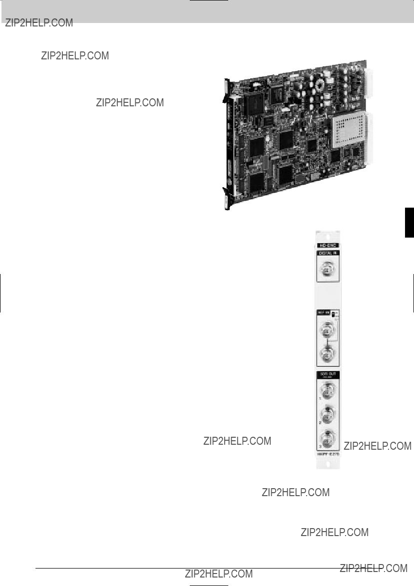
Interface Processor D Series
The
Features
* Encodes 1.5 Gb/s HD component serial digital video with eight channels of embedded audio signal into 270 Mb/s SDTI (conforming to SMPTE305M) *
The HKPF Series function boards install in the
Applicable Models
Supplied Accessories
Operation manual (1)
Maintenance manual (1)
Slot number label (1)
Interface Processor D Series
Rear Panel
113

Interface Processor D Series
Interface Processor D Series
Specifications
Inputs/outputs
Digital signal input:
DIGITAL IN (HDCAM) connector (BNC type) (1), HD serial digital signal conforming to
Input impedance: 75 ?? , unbalanced
Input return loss:
15 dB or more (5 MHz to 741.8 MHz)
10 dB or more (741.8 MHz to 1.484 GHz) Transmission loss:
20 dB or less (at 741.8 MHz) Cable length:
SDTI: 200 m max. (Using Belden 8281, Fujikura 5C2V or equivalent cable)
Active through output: 75 ?? , unbalanced
SYNC signal input:
REF IN connector (BNC type) (1) 1125 or 525 SYNC signal
Input impedance: 75 ?? , unbalanced
With 75 ?? termination switch Digital signal outputs:
SDTI (HDCAM) OUT connectors (BNC type)
(3)
HDCAM over SDTI signal conforming to SMPTE305M
Output signal amplitude:
800 m
75 ?? , unbalanced Output return loss:
15 dB or more (5 MHz to 270 MHz) Digital input/output system delay
REF lock:
2 frames (to reference) Minimum delay:
1.2 frames (to input) ISR output information
Status messages: 8 items
General
Power requirements:
+5 V DC: 1.8 A,
Power consumption: Approx.15 W
Operating temperature:
5 to 40 ??C (41 to 104 ??F) Storage temperature:
10 to 90% (without condensation) Dimensions
Board (H x W): 194 x 310 mm
(7 3/4 x 12 1/4 inches) Connector panel (H x D x W):
218 x 98 x 25 mm
(8 5/8 x 3 7/8 x 1 inches)
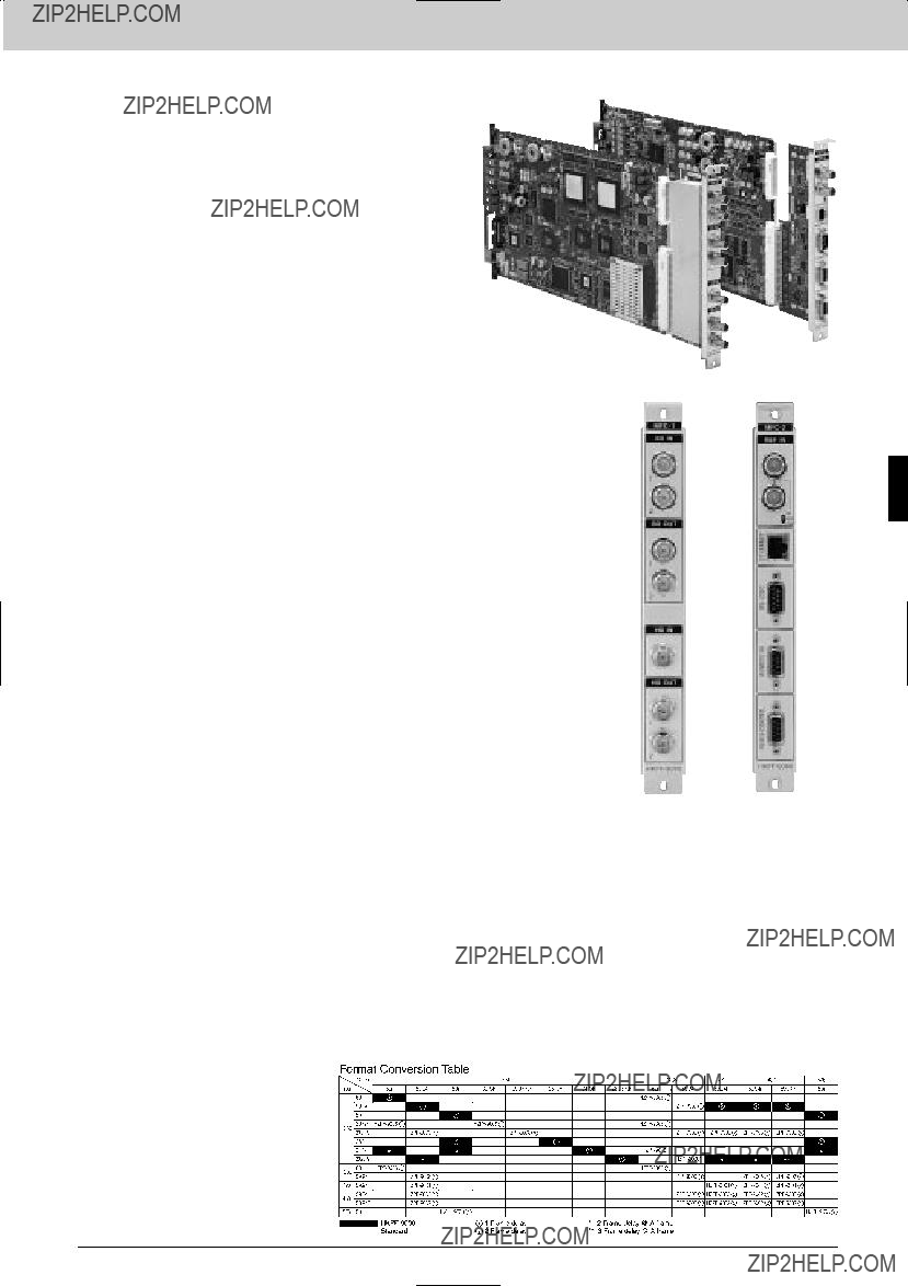
Interface Processor D Series
The
Features
The HKPF Series function boards install in the
Processor D Series
Applicable Models
Supplied Accessories
Operation manual (1)
Installation manual (1)
Optional Software
Software
Optional Peripherals
Specifications
Inputs/outputs
Digital signal inputs:
SD IN 1,2 connector (BNC type) (2), 525/625 component digital serial signal with embedded audio conforming to SMPTE259M, 270 Mb/s, 0.8
HD IN connector (BNC type) (1), HD digital serial signal with embedded audio conforming SMPTE291M/292M/ 299M, BTA
Cable length:
200 m max. (SD)
(With Fujikura 5C2V or equivalent coaxial cable)
100 m max. (HD)
(with Fujikura
Input return loss:
15 dB or more (5 MHz to 270 MHz) Reference input:
REF IN connector (BNC type) (1), 1125
Digital signal outputs:
SD OUT1, 2 connector (BNC type) (2), component digital serial signal with embedded audio conforming to SMPTE259M, 270 Mb/s, 0.8
HD OUT1, 2 connector (BNC type) (2), HD digital serial signal with embedded audio conforming SMPTE291M/292M/ 299M, BTA
Output return loss:
15 dB or more (5 MHz to 270 MHz) Jitter:
Alignment jitter, 740 ps (SD), 135 ps or less (HD)
Rise/fall time:
1.5 ns or less (SD), 270 ps or less (HD)
Remote control:
General
Power requirements:
+5 V DC: 5.0 A,
Operating temperature:
5 to 40 ??C (41 to 104 ??F)
Storage temperature:
10 to 90% (no condensation) Dimensions
Board (H x W): 194 x 310 mm
(7 3/4 x 12 1/4 inches) Connector panel (H x D x W):
218 x 98 x 25 mm
(8 5/8 x 3 7/8 x 1 inches)
Mass Board:
Approx. 700 g (1 lb 3 oz) Connector panel:
Approx. 600 g (1 lb 5 oz)
Interface
115

Interface Processor D Series
Interface Processor D Series
The
Features
*Remote control of the
Rear Panel
Operating humidity:
20 to 80% (no condensation) Dimensions:
424 x 43.6 x 171 mm
(16 3/4 x 1 3/4 x 6 3/4 inches) Mass:
Approx. 2.9 kg (4 oz)
116

Interface Processor D Series
SDTV
SDTV
Interface Processor D Series
117

Interface Processor D Series
BKPF Series boards provide a wide range of audio and video signal processing and distribution functions for analog and digital signals. The
Features
* Accommodates and powers one BKPF Series board *
Rear Panel
Supplied Accessories
Operation manual (1)
Installation manual (1)
Optional Boards
Board
Optional Software
Software
Specifications
General
Power requirements:
100 to 240 V AC, 50/60 Hz Power consumption:
100 V: 0.8 A, 240 V: 0.4 A Maximum power supply capacity:
+5 V DC: max. 2.4 A
For installed board
5 to 40 ??C (41 to 104 ??F)
Storage temperature:
10 to 90% Dimensions (W x H x D):
424 x 44 x 426 mm
(16 3/4 x 1 3/4 x 16 7/8 inches) Mass:
Approx. 5 kg (11 lb 4 oz)
(not including the optional boards)
Interface Processor D Series
118
Interface Processor D Series
BKPF Series boards provide a wide range of audio and video signal processing and distribution functions for analog and digital signals. The
Features
(not including the optional boards)
Optional Boards
The total power consumption of the four installed function boards should not exceed 8 A at 5 V and 8 A at
Interface Processor D Series
Optional Software
Software
Optional Peripherals
Specifications
Output
STATUS OUT:
General
Power requirements:
100 to 240 V AC, 50/60 Hz Power consumption:
100 V AC: max. 1.8 A
240 V AC: max. 0.9 A Maximum power supply capacity:
+5 V DC: max. 8 A
For installed boards
5 to 40 ??C (41 to 104 ??F) Storage temperature:
10 to 90%
119
Interface Processor D Series
BKPF Series boards provide a wide range of audio and video signal processing and distribution functions for analog and digital signals. The
Features
* Accommodates and powers fourteen BKPF Series boards *
Redundant power supply option * Supports ISR
Interface Processor D Series
Supplied Accessories
Operation manual (1)
Installation manual (1)
Optional Accessories
Optional Boards
Optional Software
Software
Optional Peripherals
Specifications
Output
STATUS OUT:
General
Power requirements:
100 to 240 V AC, 50/60 Hz
Rear Panel
Power consumption: 600 VA max.
Maximum power supply capacity: +5 V DC: max. 23 A
For installed boards
5 to 40 ??C (41 to 104 ??F) Storage temperature:
10 to 90% Dimensions (W x H x D)
424 x 310 x 450 mm
(16 3/4 x 12 1/4 x 17 3/4 inches) Mass:
Approx. 18 kg (39 lb 11 oz)
(not including the optional boards)
The total power consumption of the14 installed function boards should not exceed 23 A at 5 V and 23 A at
120
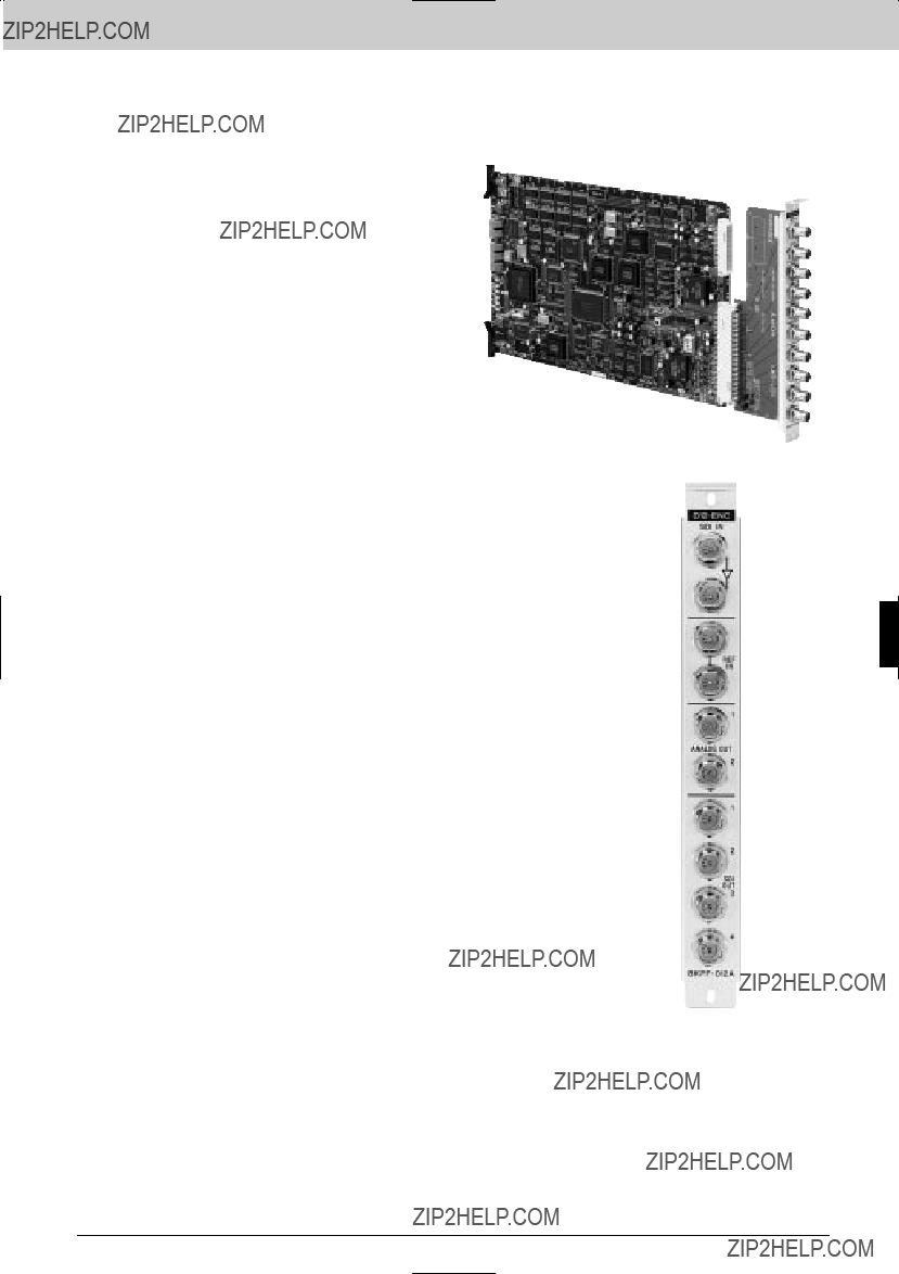
Interface Processor D Series
analog/digital video converter board
The
Features
* Converts a
The BKPF Series function boards install in both the
Applicable Models
Interface Processor D Series
Rear Panel
121
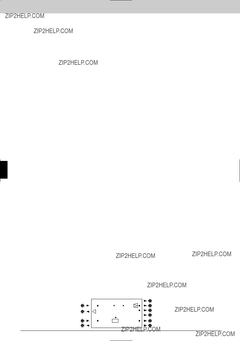
Interface Processor D Series
Interface Processor D Series
NTSC COMPOSITE SERIAL
DIGITAL VIDEO
NTSC COMPOSITE ANALOG VIDEO
122

Interface Processor D Series
Video Converter Board
The
Features
* Converts an NTSC composite serial digital video signal to a
The BKPF Series function boards install in both the
Applicable Models
Specifications
Inputs/outputs
Serial digital input:
SDI IN connector (BNC type) (1) 0.8
NTSC composite serial digital signal conforming to
Cable length:
200 m max. (When using a Belden 8281, Fujikura 5C2V or equivalent coaxial cable)
Serial digital outputs:
Active
0.8
Serial digital video signal of the same format as that to the input connector SDI OUT connectors (BNC type) (4)
0.8
Reference video input:
REF IN connector (BNC type) (1) Reference video output:
System delay: Approx. 70.5 ??s
(in INPUT mode, with SYSTEM
Output phase adjustable range:
Coarse adjustment:
in INPUT mode: 0 to +9.44 ??s (0 to +255 CK)
(1 CK: approx. 37 nsec)
More than 58 dB DG (10 kHz to video fg.)
General
Power requirements:
+5 V DC: 1400 mA,
Power consumption: 10 W
Operating temperature:
5 to 40 ??C (41 to 104 ??F) Storage temperature:
10 to 90% (no condensation) Dimensions
Board (H x W): 195 x 310 mm
(7 3/4 x 12 1/4 inches) Connector panel (H x W):
195 x 25 mm
(7 3/4 x 1 inches)
Mass Board:
Approx. 650 g (1 lb 7 oz) Connector panel:
Approx. 200 g (7 oz)
Rear Panel
Interface Processor D Series

Interface Processor D Series
The
Features
*Converts four analog audio signals to two AES/EBU digital audio signals. * Multiplexes the two AES/EBU signals onto a 525/625 component serial digital or NTSC composite serial digital video signal * Audio mute function
*Supports ISR * Supports EDH
The BKPF Series function boards install in both the
Applicable Models
Optional Accessories
Type Digital Audio Interface Cable
Interface Processor D Series
Rear Panel
124
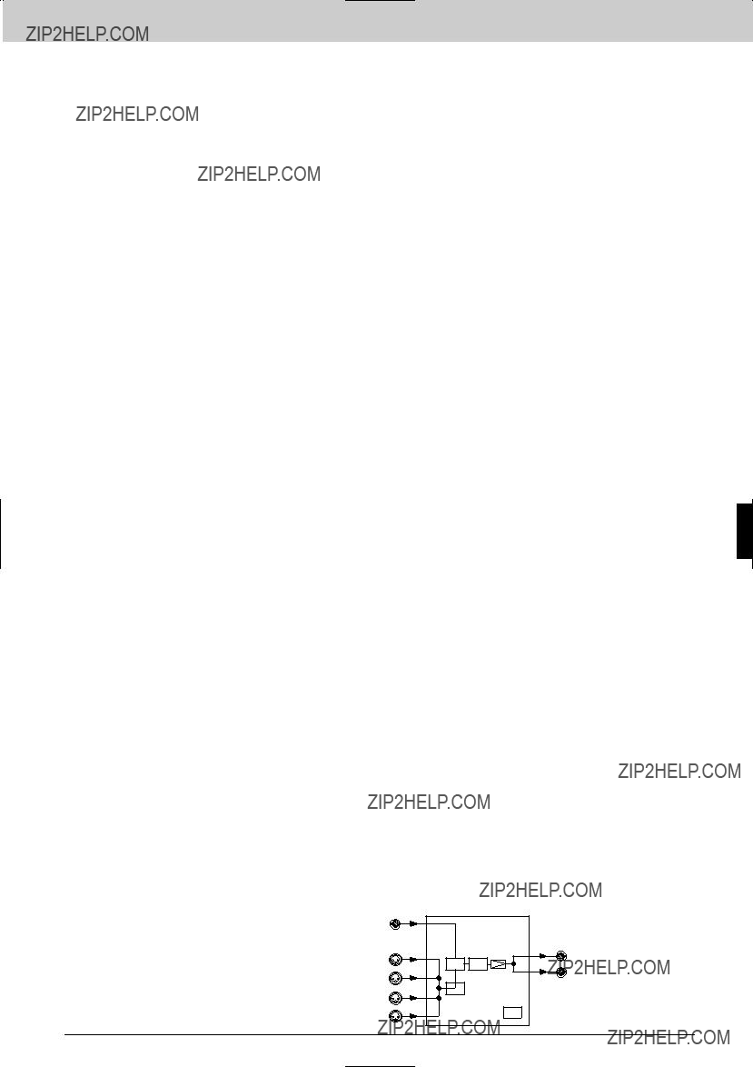
Interface Processor D Series
Conversion characteristics
NTSC COMPOSITE/ 525/625 COMPONENT
SERIAL DIGITAL VIDEO
WITH EMBEDDED AUDIO
Interface Processor D Series
125
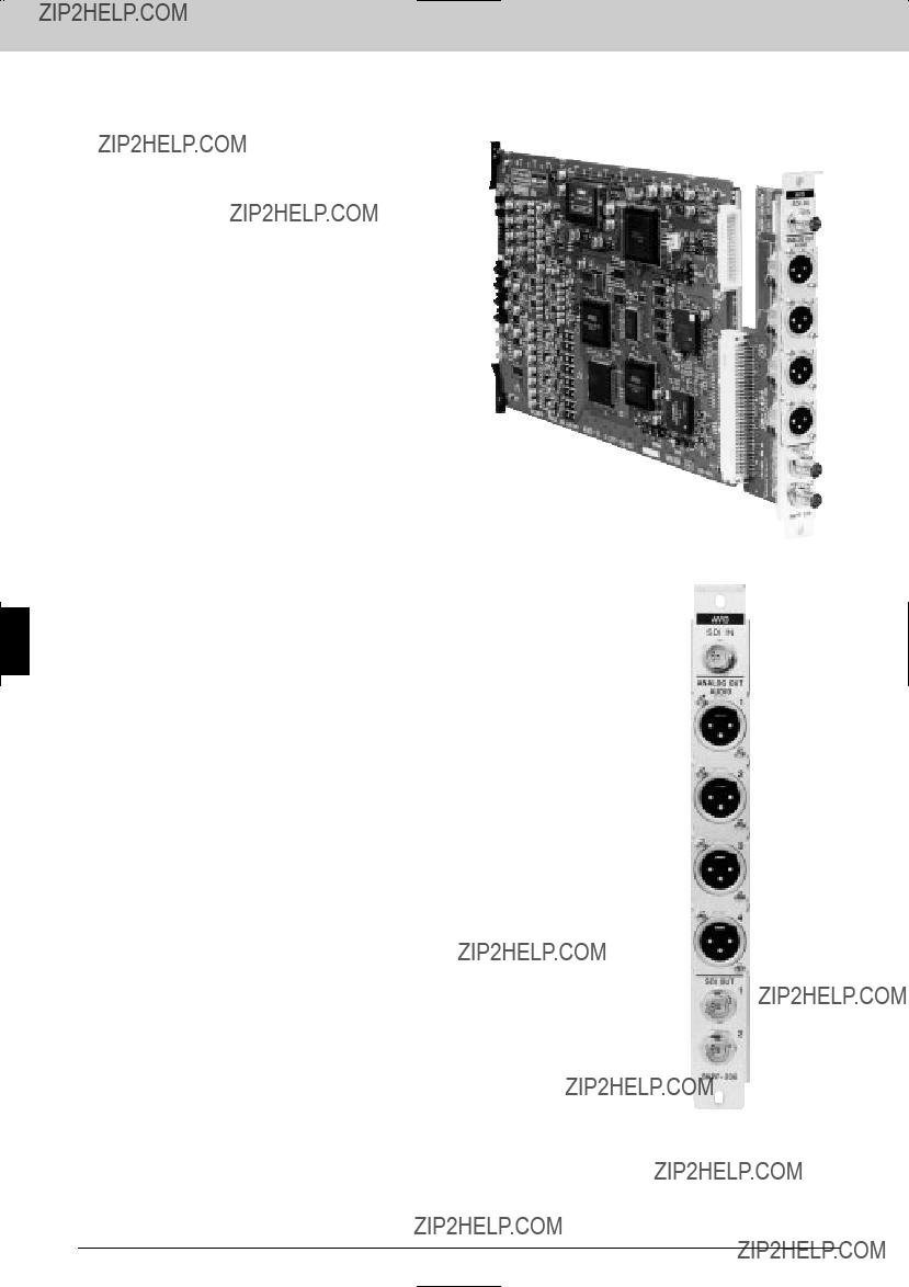
Interface Processor D Series
The
Features
* Demultiplexes AES/EBU digital audio signals multiplexed onto a 525/625 component serial digital or NTSC composite serial digital video signal * Demultiplexing audio group selection (with a component serial digital video signal input) * Supports ISR * Supports EDH
The BKPF Series function boards install in both the
Applicable Models
Optional Accessories
Type Digital Audio Interface Cable
Interface Processor D Series
Rear Panel
126
Interface Processor D Series
NTSC COMPOSITE/ 525/625 COMPONENT
SERIAL DIGITAL VIDEO
OUTPUT
ANALOG AUDIO
OUTPUT
Interface Processor D Series
127

Interface Processor D Series
Interface Processor D Series
The
Features
* Eight input, two output, switching matrix * Simultaneous control of multiple signals with matrix level setting * Control from
The BKPF Series function boards install in both the
Applicable Models
Specifications
Inputs/outputs
SDI inputs:
SDI IN connectors (BNC type) (8) NTSC composite or 525/625 component serial digital signal conforming to
(Selectable with
SDI OUT connectors (BNC type) (2) Serial digital video signal of the same format as that to the input connector 0.8
Input/output impedance: 75 ??
Input/output return loss:
More than 15 dB (at 5 MHz to 270 MHz) Cable length:
200 m max. (When using a Belden 8281, Fujikura 5C2V or equivalent coaxial cable)
Rise and fall time: Less than 1.5 ns
ISR output information Status messages:
3 items Setup messages:
2 items
General
Power requirements:
+5 V DC, 0.5 A,
Power consumption: Approx. 7.5 W
Operating temperature:
5 to 40 ??C (41 to 104 ??F) Dimensions (H x W)
Board:
195 x 310 mm
(7 3/4 x 12 1/4 inches) Connector panel:
195 x 25 mm
(7 3/4 x 1 inches)
Mass Board:
Approx. 550 g (1 lb 3 oz) Connector panel:
Approx. 200 g (7 oz)
Rear Panel
NTSC COMPOSITE/ 525/625 COMPONENT
SERIAL DIGITAL SIGNAL
INPUT
NTSC COMPOSITE/
1 525/625 COMPONENT
 2 SERIAL DIGITAL SIGNAL
OUTPUT
128
Interface Processor D Series
The
Features
* Eight input, two output, switching matrix * Simultaneous control of multiple signals with matrix level setting * Control from
The BKPF Series function boards install in both the
Rear Panel
NTSC/PAL
COMPOSITE ANALOG
VIDEO SIGNAL INPUT
 1 NTSC/PAL
COMPOSITE ANALOG
 2 VIDEO SIGNAL OUTPUT
Interface Processor D Series
129
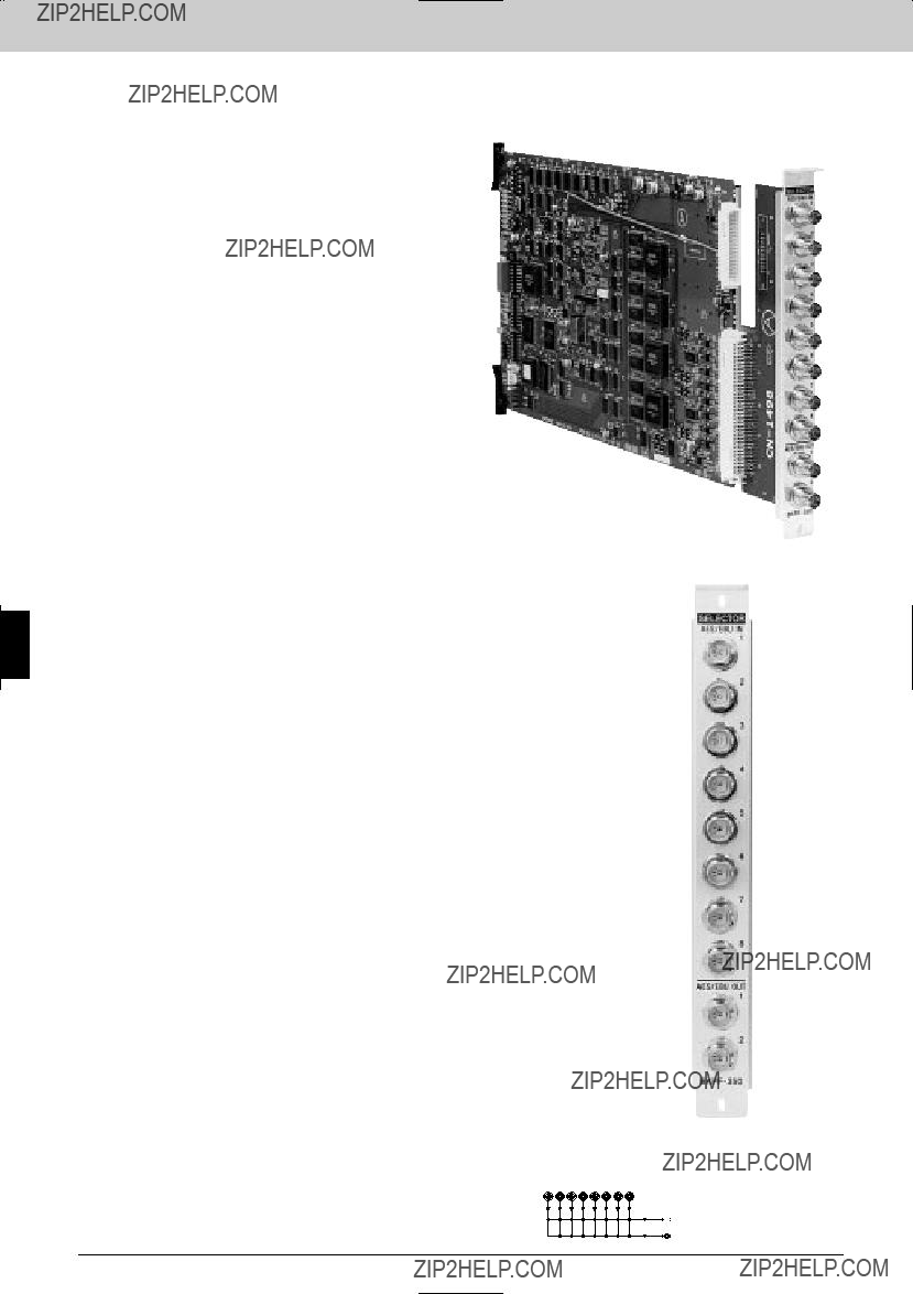
Interface Processor D Series
Interface Processor D Series
The
Features
* Eight input, two output, switching matrix * Simultaneous control of multiple signals with matrix level setting * Control from
The BKPF Series function boards install in both the
Applicable Models
Specifications
Inputs/outputs
Audio signal inputs:
AES/EBU IN connectors (BNC type) (8) Audio signal outputs:
AES/EBU OUT connectors (BNC type)
(2)
Rise and fall time: 37 ns
DC offset:
Less than 650 mV ISR output information Status messages:
3 items
Setup messages: 1 item
General
Power requirements:
+5 V DC, 0.5 A,
Power consumption: Approx. 6 W
Operating temperature:
5 to 40 ??C (41 to 104 ??F) Dimensions (H x W)
Board:
195 x 310 mm
(7 3/4 x 12 1/4 inches) Connector panel:
195 x 25 mm
(7 3/4 x 1 inches)
Mass Board:
Approx. 550 g (1 lb 3 oz) Connector panel:
Approx. 200 g (7 oz)
Rear Panel
AES/EBU DIGITAL
AUDIO INPUT
 1 AES/EBU DIGITAL
 2 AUDIO OUTPUT
130

Interface Processor D Series
The
Features
* Eight analog stereo inputs, one stereo output switching matrix * Simultaneous control of multiple signals with matrix level setting * Control from
Applicable Models
Specifications
Inputs/outputs
Audio input:
ANALOG AUDIO IN (L) (R) connectors
(1 each) Audio output:
ANALOG AUDIO OUT connector (Phoenix type
Input impedance:
20 k?? /600 ?? (selectable with
Output impedance: Approx. 22 ??
Nominal input/output level: +4 dBm
Maximum input level: +24 dBm
Maximum output level:
+24 dBm (600 ?? load, balanced) Frequency response:
60.1 dB (20 Hz to 20 kHz, 1 kHz+4 dBm)
Distortion:
0.01% (20 Hz to 20 kHz, at +24 dBm output)
Crosstalk:
Less than
More than 105 dB (30 kHz LPF, at nominal level)
ISR output information Status messages:
3 items
Setup messages: 1 item
General
Power requirements: +5 V DC, 0.5 A
(supplied from the
Power consumption: Approx. 8 W
Operating temperature:
5 ??C to 40 ??C (41 ??F to 104 ??F) Dimensions (H x W)
Board:
195 x 310 mm (7 3/4 x 12 1/4 inches) Connector panel:
195 x 25 mm (7 3/4 x 1 inches)
Mass Board:
Approx. 550 g (1 lb 3 oz) Connector panel:
Approx. 200 g (7 oz)
Interface Processor D Series
131

Interface Processor D Series
Interface Processor D Series
132
Interface Processor Others
Interface Processor Others
133
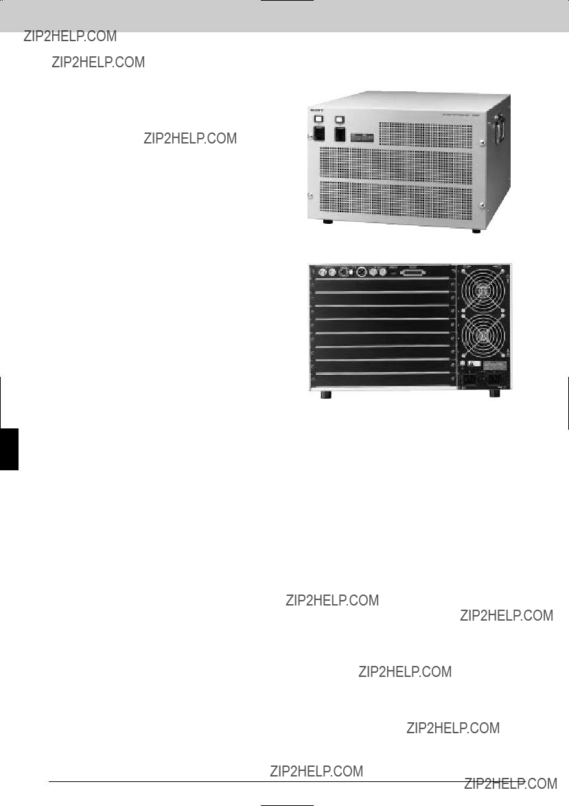
Interface Processor Others
Interface Processor Others
Features
*Forms the core of a FlexSys system *Can accommodate up to eight BKSI Series boards *Continuous operation ??? the redundant power supply unit can be
Optional Boards
Board
CPU Board
Board
Optional Software
Rear Panel
Specifications
Inputs/outputs
Input:
REF VIDEO INPUT connector (BNC type) (1)
Active
(1)
REMOTE:
Active
(1)
General
Power requirements:
AC 100 to 240 V 610%, 50/60 Hz Power consumption:
Max. 400 W Operation temperature:
5 to 40 ??C (41 to 104 ??F) Operating humidity:
10 to 90% (no condensation) Dimensions (W x H x D):
424 3 265 3 470 mm
(16 3/4 x 10 1/2 x 18 5/8 inches) Mass:
Approx. 15 kg (33 lb 1 oz)
134
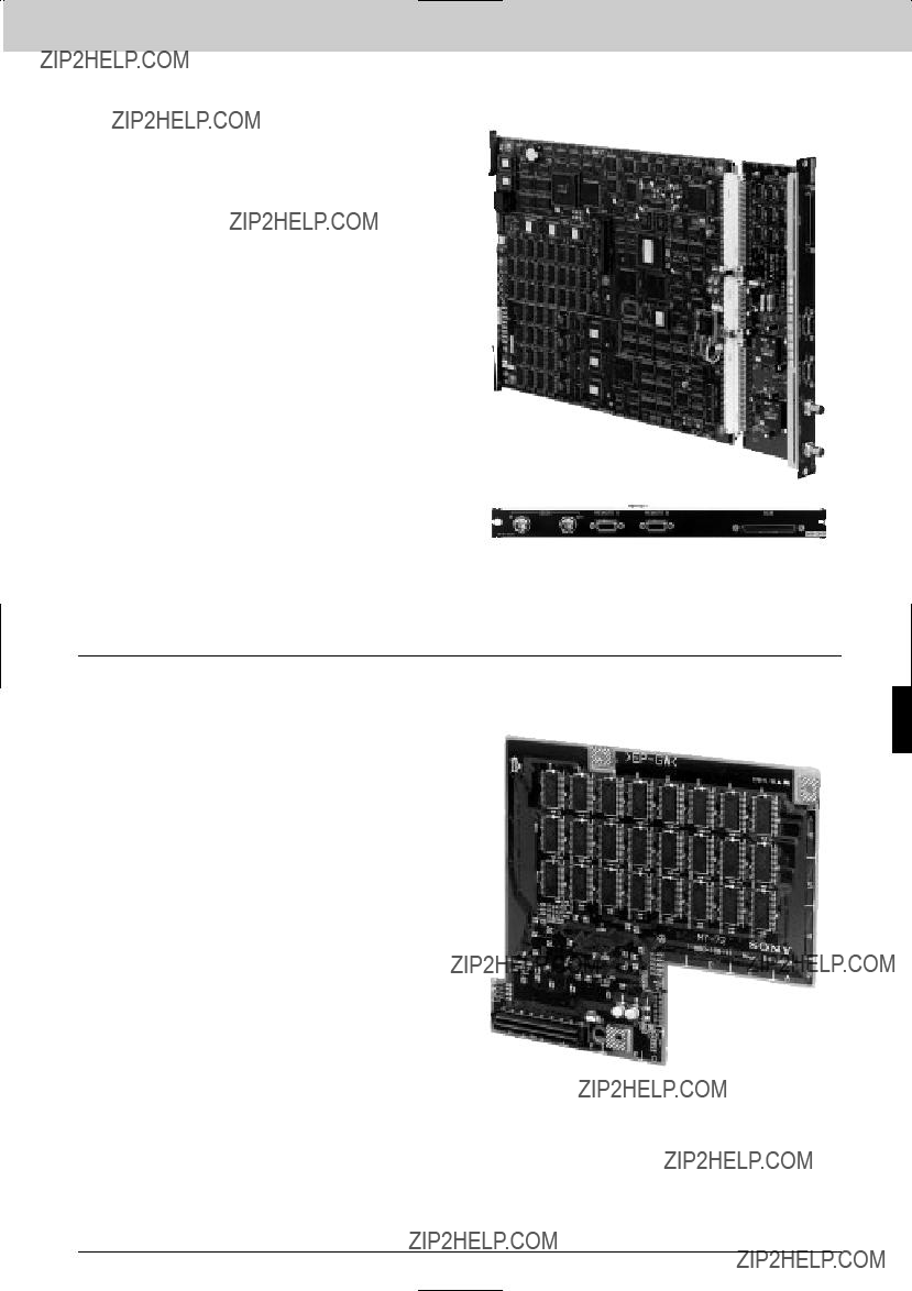
Interface Processor Others
The
Applicable Models
Rear Panel
The
Applicable Models
Interface Processor Others
135

Interface Processor Others
Interface Processor Others
The
Applicable Models
Rear Panel
The
Applicable Models
Rear Panel
136
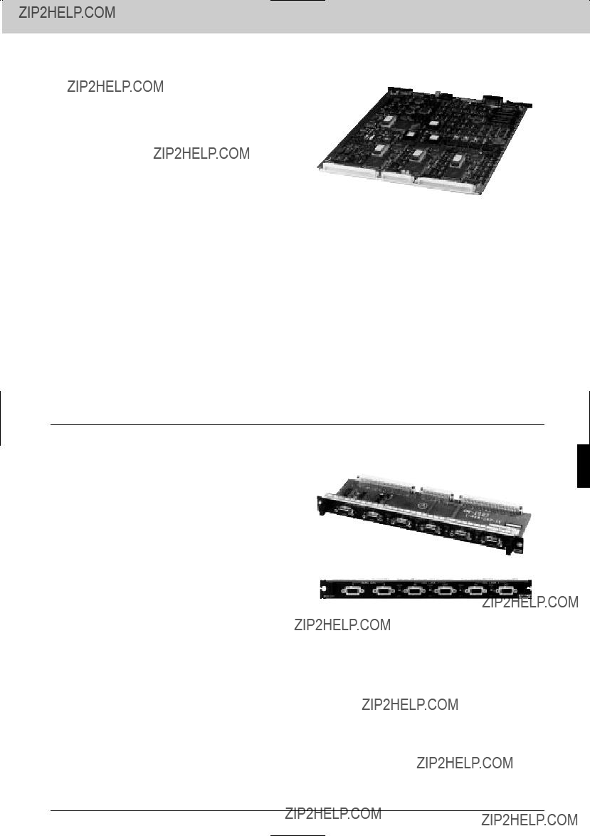
Interface Processor Others
The
Applicable Models
The
Applicable Models
Rear Panel
Interface Processor Others
137

Interface Processor Others
Interface Processor Others
The
Applicable Models
Rear Panel
The
Applicable Models
Rear Panel
138
Interface Processor Others
The
Applicable Models
Rear Panel
The
Applicable Models
Rear Panel
Interface Processor Others
139
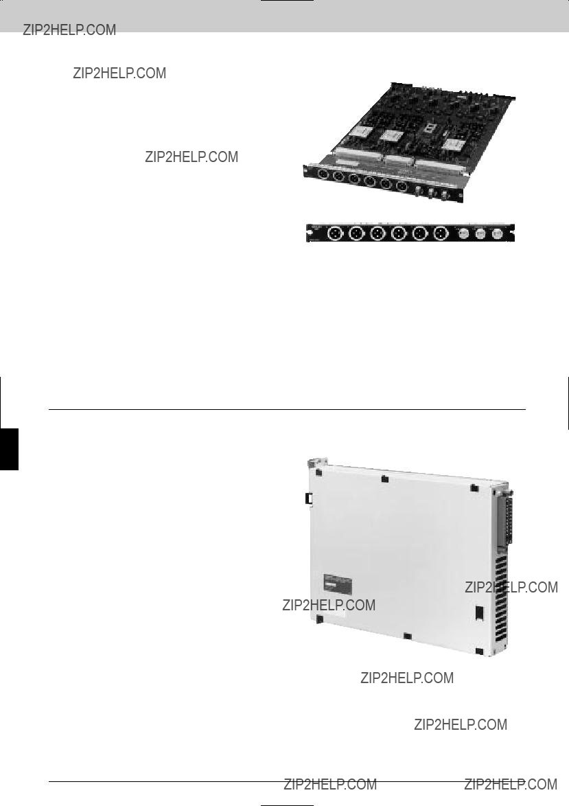
Interface Processor Others
The
Applicable Models
Rear Panel
Interface Processor Others
The
140

Interface Processor Others
141
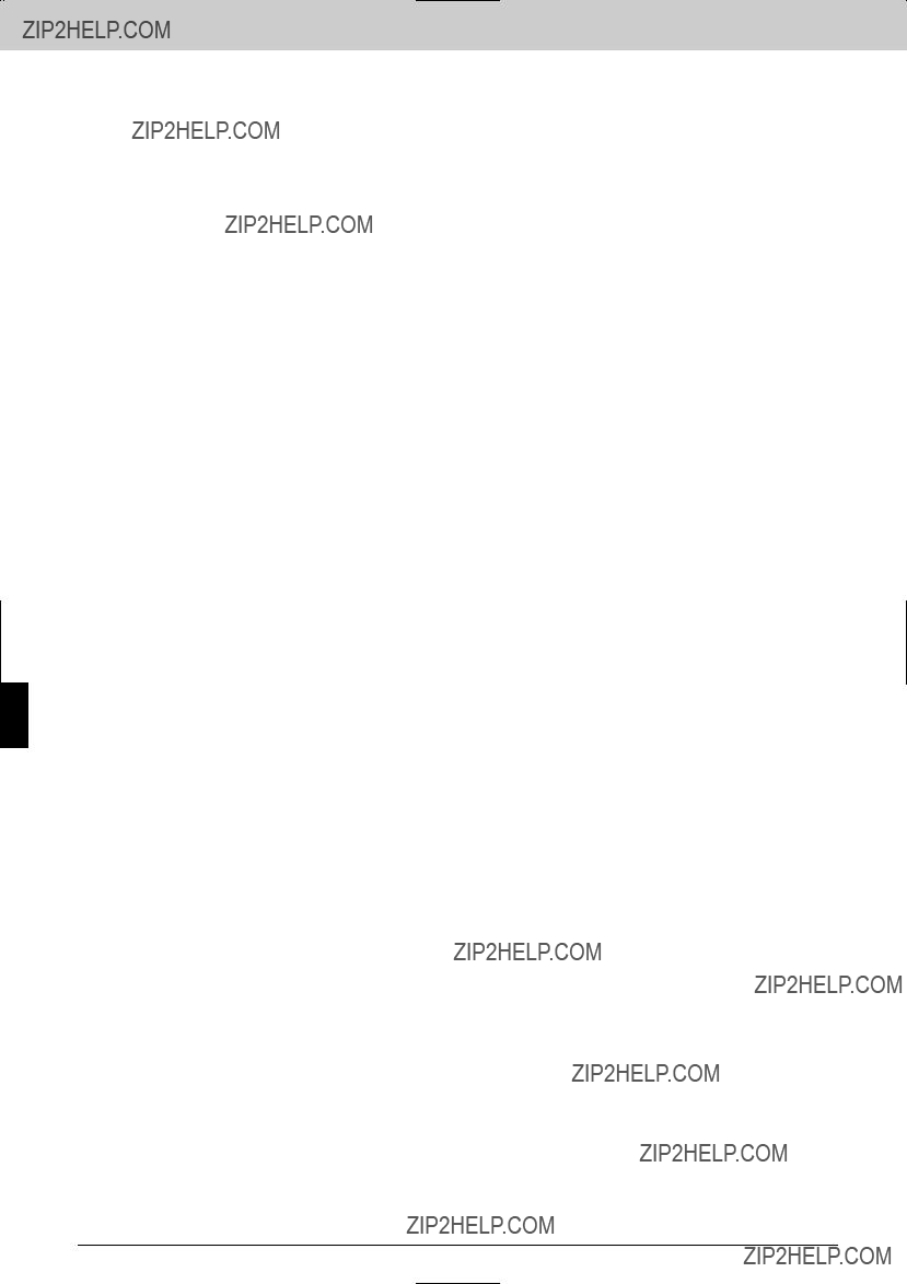
Interface Processor Others
Interface Processor Others
142

PRODUCT INDEX
GENERAL INDEX
A
B
D
E
H
P
R
S
U
PRODUCT INDEX
143
PRODUCT INDEX
PRODUCT INDEX
CATEGORY INDEX
Cables
Common Accessories
Interface Processor D Series
Interface Processor L Series
Interface Processor SP Series
Routing Switchers
144

Technical References
Routing Switchers . . . . . . . . 146 ISR . . . . . . . . . . . . . . . . . . . 158 EDH . . . . . . . . . . . . . . . . . . 160
145
Technical References
Routing Switchers
Introduction to the Sony Signal Routing System
The Sony routing system on a complete range of flexible, modular, signal routing matrixes. It interfaces to other routing equipment, production and presentation switchers, tally and UMD systems to from
???
???
???
???
???
???
???
???
Some router types have the capability of being expanded to form a lager matrix.
For example, an
When forming a
Supporting the overall range is the Routing Controll System, a highty sophisticated local area network called Sony
146

Technical References
Free I/O assingment across all levels
???any source or destination can be freely assigned to any crosspoint regardless of physical connection
Full signal breakaway
??? sources in a multilevel system can be switched married or unmarried
Descriptive naming
??? sources and destinations can be named to match the user???s needs
Virtual matrix management
??? matrix can be placed virtualy within
???
Source, destination and crosspoint protection mechanisms
??? sources and destination can be inhibited, protected or made secret
Password protection
??? passwords can be used to restrict the personnel able to make changes
Powerful phantom facilities
??? multiple crosspoint changes can be made from a single
In addition to
System Control
A wide range of control units is available a Sony routing system.
???Sixteen and
???
???
???X/Y control units
Some of these units support VTR transport control, level switching and destination control. A unique feature is that unit software and
Extenderd control features, provided by
???graphic displays of crosspoint maps
???interactive graphics for system configuration
???display of video signal sources and destinations on a PC VDU
???
147

Technical References
Integrated Systems
A key element of Sony routing systems is their ability to provide an integrated solution for the user. Sony routing systems can be interfaced to Sony
Legacy
Within
Critical Applications
In any
Sony routing systems are no exception to this philosophy. Backup power supplies are available for most routing and interfacting equipment.
Redundancy also extends to being able to provide backup control boards for the CPUs in a routing system.
In addition to providing redundant power supplies and control boards, data is held in
148
Technical References
BVP/HDC SERIES
VIDEO CAMERA
VIDEO SWITCHER
THIRD PARTY
ROUTING SYSTEM
149

Technical References
Powerful Matrix Control Functions of Sony
The introduction of the Sony multi
???Space and cost saving
???SD SDI & HD SDI in a single frame under the same control
???Flexible and simple SD/HD migration
???Efficient use of conversion equipment
???Sharing up/down converters between multiple signal paths
Using the
The multi
The
150

Technical References
Input/output system protection functions (protect and secret functions)
There are two protection functions:
???Protect??? function prevents the output destination from being
???Secret??? function ???hides??? the input sources that cannot be selected to any destination from any remote control panel.
Crosspoint disabling function
This function inhibits individual crosspoints to limit the availability of each source to individual destinations.
xxxxxxxxxxxxxxxx xxxxxxxx xxxxxxxx xxxxxxxx xxxxxxxx xxxxxxxx xxxxxxxx xxxxxxxx xxxxxxxx xxxxxxxx xxxxxxxx xxxxxxxx xxxxxxxx xxxxxxxx xxxxxxxx xxxxxxxx xxxxxxxx xxxxxxxx xxxxxxxx xxxxxxxx xxxxxxxx xxxxxxxx xxxxxxxx xxxxxxxx xxxxxxxx xxxxxxxx xxxxxxxx xxxxxxxx xxxxxxxx
xxxxxxxxxxxxxxxx xxxxxxxx xxxxxxxx xxxxxxxx xxxxxxxx xxxxxxxx xxxxxxxx xxxxxxxx xxxxxxxx xxxxxxxx xxxxxxxx xxxxxxxx xxxxxxxx xxxxxxxx xxxxxxxx xxxxxxxx xxxxxxxx xxxxxxxx xxxxxxxx xxxxxxxx xxxxxxxx xxxxxxxx xxxxxxxx xxxxxxxx xxxxxxxx xxxxxxxx xxxxxxxx xxxxxxxx xxxxxxxx xxxxxxxx xxxxxxxx xxxxxxxx xxxxxxxx xxxxxxxx xxxxxxxx xxxxxxxx xxxxxxxx xxxxxxxx xxxxxxxx
Phantom function (salvo function)
This function allows the switching of multiple crosspoints at the same time with a single button operation. The following two types of settings can be made:
(1)???Local phantom???: Registers up to 64 crosspoints for each remote control panel.
(2)???Global phantom???: Registers up to 2,800 crosspoints for the routing switchers set by the primary stations.
Names can be set for phantoms (groups of crosspoints switched simultaneously). Since local phantoms are registered for each remote control panel, the same name can be used for a different group of crosspoints on each remote control panel.
On the other hand, global phantoms are useful when there are many crosspoints to switch simultaneously, or when sharing the same phantom across multiple remote control panels. Also, the number of phantoms set for each unit can be increased by combining global phantoms and local phantoms.
151

Technical References
Name setting function
Names can be set for Sources and Destinations in order to identify the signals connected.
The following two methods are available for setting names.
(1)???Type name (VTR, CAM, etc.) + Number???: 32 names each comprising up to four letters and three numbers.
(2)???Descriptive name (REPORT_FROM_LA, etc)???: Name made of up to 16 Latin alphanumeric characters.
Eight group of data can be registered within the primary station with each group containing 160 descriptive names. This data can be sent and displayed on UMDs (Under Monitor Displays) and remote control panels.
Free assignment of inputs and outputs allows sources and destinations on different levels to be grouped under a single source or destination name. For example the video, audio and time code signals of
but could be assigned as, say, channel 1 of the video router, channel 10 of the audio router and channel 12 of the time code router. This function provides a much more flexible signal- handling environment.
152
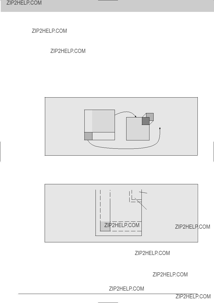
Technical References
Virtual mapping function
This function lays out routing switcher crosspoints on a virtual matrix of 1024 inputs x 1024 outputs when eight levels are used or 1024 inputs x 512 outputs when 16 levels are used.
The virtual mapping capability of Sony routing switchers features two types of mapping:
(1)A single routing switcher can be mapped to operate as a number of individual routing switchers. For example, a single 256 x 256 multi bit rate routing switcher can be divided into, say, a 192 x 192 switcher and a 64 x 64 switcher so that the corresponding crosspoints on these two levels are switched simultaneously. This allows a 192 x 192 HD switcher and a 64 x 64 SD switcher to be created
Virtual Mapping Function Concept Diagram 1
(2)Multiple routing switchers can be mapped on a larger, virtual routing level
136
150
Virtual Matrix Space
Virtual Mapping Function Concept Diagram 2
This function can send information on errors and the presence/absence of inputs to a control
terminal connected to the primary station for display.
153

Technical References
Main Features of the
Support for multiple bit rates independent of signal format
These switches support not only HD SDI, but also various other transmission rates of SDI (540 Mb/s, 360 Mb/s, 270 Mb/s and 143 Mb/s) and SDTI (Table 1), and support embedded AES/EBU Audio.
Both
Table 1 Signal Formats Supported by the
* Rise and fall times of
Modular structures for flexible construction and expansion of different sizes of matrix
easily increased in size and format as required.
154

Technical References
155

Technical References
Affinity with and expandability in current broadcast and production environments.
environments, providing:
(1)
(2)59.94 and 50 Hz vertical sync both possible
(3)Simultaneous control of multiple signals through level settings
(4)Four systems of signal switching control ???
Compact and space saving
Every possible measure has been taken to reduce the space requirements of
Securing maintainability and reliability
Although designed to be compact, maintenance and reliability have not been compromised:
(1)Backup power supplies and CPU boards are available on most models
(2)Crosspoint data storage
(3)Board maintenance from front
(4)Fault notice functions
156

Technical References
OUT
OUT
OUT
OUT
*Remarks: Maximum size is thecrefically (Physically) 1056 x1090 but 1024 x 1024 effectually due to current
Cascade Connection Example of
Features and specifications are subject to change without notice.
157
Technical References
Technical References: ISR
Television broadcast and production systems become ever more complex and the ability to monitor equipment ever more important ??? but at the same time increasingly difficult. Equipment downtime can have a dramatic effect on revenue, so knowledge of potential equipment failure is of great value. The solution is the Sony ISR (Interactive Status Reporting) system, which allows a wide range of digital broadcast equipment to be remotely monitored.
Digital equipment has brought new levels of performance and operational benefits at every stage of the program making process - acquisition, production, post and play out. These benefits now include detailed equipment database management, allowing significant improvements to be made in operating efficiency.
ISR provides status reporting, error logging and remote control and remote diagnostics on VTRs, camera systems, routers, servers, switchers and edit controllers. This wealth of information brings levels of centralized system management never before possible.
ISR runs on
The ISR system
???Status monitoring provides continuous displays of
???error and warning status of equipment
???VTR channel condition
???EDH and EDA status of equipment
???system log files status
???Remote diagnostics
???diagnostic checks of remote equipment
???intelligent remote control functions for VTRs
???Database management
???reception and storage of error and warning messages, logged by device serial number
???selective or complete uploading, storage, editing, and downloading of VTR
???management and retrieval of historical data
???logging of VTR channel condition, with time stamp and time code
???management of equipment in discrete groups
???export of data to Microsoft Excel???
???Software options
???
???
???
???more than one supervisory node can exist on the same system
*May require an additional
**Will require network components and software
***Requires NT 3.51 server if more than three 500/501 nodes exist on the same system
158
Technical References
Conceptual ISR Configurations
ENGINEERING MAINTENANCE
APPLICATION FOR
CONTROLLING UP TO 64
UNITS IN DIFFERENT
TECHNICAL AREAS
ETHERNET REPEATER
A CAMERA CONTROL
ENVIRONMENT
159

Technical References
Technical References: EDH
EDH ??? Error Detection and Handling
The need for EDH
Video installations never get any simpler. In fact, the growth in viewer expectations of seeing what they want when they want, has resulted in a huge, world wide expansion in systems devoted to the switching and routing of video signals. Continuous quality monitoring of every signal path is, in many cases, impractical. Signals may arrive at a switching center, be routed to a destination, and leave the center without any check being made to ensure that the signal going out is as good as the signal coming in. When these signals are serial digital video, their inherent resistance to distortion will generally mean that they do pass through a system unchanged. However, a digital signal can have deteriorated to the point where a minor equipment fault or a few extra meters of cable can cause a catastrophic failure. EDH has been developed as a way of avoiding this type of situation and is supported by SMPTE RP165 as an
The concept of EDH
The concept of EDH is very simple. The data bits making up the each frame of a serial digital video signal are 'counted' to generate a check sum. This check sum is inserted in the blanking interval of the same video frame. At a later point along the path of the video signal, the check sum for each individual video frame is recalculated and compared to the check sum carried in its blanking period. If the sums do not agree, then data corruption has occurred somewhere between these two points.
In a practical system this basic concept is expanded and refined to become a valuable tool in an operational environment. The ultimate use of EDH in a system is that every item of video equipment has the ability to carry out this checking process so that the precise point of data corruption can be located.
EDH in practice
Once the check sums have been attached to each frame of a video signal, identifying the point where data errors have been introduced is carried out by a
???The check sum for the frame is recalculated.
???This check sum is compared to the check sum in the blanking interval. If they do not agree, a warning flag is generated to warn of data corruption earlier in the signal path.
???The recalculated check sum is inserted into the blanking period, replacing the previous one so that the checking process can continue.
This recalculating and comparing process can happen as often as required, the more frequently it is done the greater the accuracy in determining where data corruption has occurred in the signal path.
160
Technical References
Error reporting
Errors are reported in five different ways:
???Error detected here, edh
???Error detected already, eda
???Unknown error status, ues
???Internal error detected here, idh
???Internal error detected already, ida
The last two reports, idh and ida, are used when a piece of equipment has the capability to check for data corruption between its input and output.
EDH actually checks and reports each video frame in three ways, calculating separate check sums for the complete frame, the active picture area and the ancillary area. (The ancillary area is the area of the frame blanking interval that can contain digital audio signals and other multiplexed information.) A reason for this division of areas is so that errors in the active picture area can be given a higher fault priority, simply because they have direct effect on the program audience.
Sony is supporting EDH, and an increasing number of relevant products(down to board level in some cases) now have the ability to provide a visual eda report with an LED indicator.
EDH and ISR
In an overall system,
161

??2002 Sony Corporation. All rights reserved.
Reproduction in whole or in part without written permission of Sny is prohibited. Features and specifications subject to change without notice.
All
Betacam and Betacam SP are trademarks of Sony Corporation. Belden is a registered trademark of Cooper Industries.
All other trademarks are the properties of their respective owners.
Distributed by