Multi Format
Compact Switcher
Operating Instructions (Volume I Basic Operation)
Before operating the unit, please read this manual thoroughly and retain it for future reference.
Software Version 1.00
Multi Format
Compact Switcher
Operating Instructions (Volume I Basic Operation)
Before operating the unit, please read this manual thoroughly and retain it for future reference.
Software Version 1.00

Owner???s Record
The model and serial numbers are located on the bottom. Record these numbers in the spaces provided below. Refer to these numbers whenever you call upon your Sony dealer regarding this product.
WARNING
To reduce the risk of fire or electric shock, do not expose this apparatus to rain or moisture.
To avoid electrical shock, do not open the cabinet. Refer servicing to qualified personnel only.
THIS APPARATUS MUST BE EARTHED.
This symbol is intended to alert the user to the presence of important operating and maintenance (servicing) instructions in the literature accompanying the appliance.
When installing the installation space must be secured in consideration of the ventilation and service operation.
???Do not block the ventilation slots at the left side and right side panels, and vents of the fans.
???Leave a space around the unit for ventilation.
???Leave more than 40 cm (15 3/4 in.) of space in the rear of
the unit to secure the operation area.
When the unit is installed on the desk or the like, leave at least 10 cm (4 in.) of space in the left and right sides. Leaving 40 cm (15 3/4 in.) or more of space above the unit is recommended for service operation.
WARNING: THIS WARNING IS APPLICABLE FOR
USA ONLY.
If used in USA, use the UL LISTED power cord specified below.
DO NOT USE ANY OTHER POWER CORD.
Using this unit at a voltage other than 120 V may require the use of a different line cord or attachment plug, or both. To reduce the risk of fire or electric shock, refer servicing to qualified service personnel.
WARNING: THIS WARNING IS APPLICABLE FOR
OTHER COUNTRIES.
1.Use the approved Power Cord
2.Use the Power Cord
If you have questions on the use of the above Power Cord / Appliance Connector / Plug, please consult a qualified service personnel.
For the customers in the U.S.A.
This equipment has been tested and found to comply with the limits for a Class A digital device, pursuant to Part 15 of the FCC Rules. These limits are designed to provide reasonable protection against harmful interference when the equipment is operated in a commercial environment. This equipment generates, uses, and can radiate radio frequency energy and, if not installed and used in accordance with the instruction manual, may cause harmful interference to radio communications. Operation of this equipment in a residential area is likely to cause harmful interference in which case the user will be required to correct the interference at his own expense.
You are cautioned that any changes or modifications not expressly approved in this manual could void your authority to operate this equipment.
All interface cables used to connect peripherals must be shielded in order to comply with the limits for a digital device pursuant to Subpart B of Part 15 of FCC Rules.
This device complies with Part 15 of the FCC Rules. Operation is subject to the following two conditions: (1) this device may not cause harmful interference, and (2) this device must accept any interference received, including interference that may cause undesired operation.
For the customers in Canada
This Class A digital apparatus complies with Canadian

For the customers in Europe
This product with the CE marking complies with the EMC Directive issued by the Commission of the European Community.
Compliance with this directive implies conformity to the following European standards:
???
???
The manufacturer of this product is Sony Corporation,
The Authorized Representative for EMC and product safety is Sony Deutschland GmbH, Hedelfinger Strasse 61, 70327 Stuttgart, Germany. For any service or guarantee matters please refer to the addresses given in separate service or guarantee documents.
For kundene i Norge
Dette utstyret kan kobles til et
For the State of California, USA only
Perchlorate Material - special handling may apply, See www.dtsc.ca.gov/hazardouswaste/perchlorate Perchlorate Material : Lithium battery contains perchlorate.
For the customers in Taiwan only
AVERTISSEMENT
Afin de r??duire les risques d???incendie ou d?????lectrocution, ne pas exposer cet appareil ?? la pluie ou ?? l???humidit??.
Afin d?????carter tout risque d?????lectrocution, garder le coffret ferm??. Ne confier l???entretien de l???appareil qu????? un personnel qualifi??.
CET APPAREIL DOIT ??TRE RELI?? ?? LA
TERRE.
AVERTISSEMENT
1.Utilisez un cordon d???alimentation (c??ble secteur ?? 3 fils)/fiche femelle/fiche m??le avec des contacts de mise ?? la terre conformes ?? la r??glementation de s??curit?? locale applicable.
2.Utilisez un cordon d???alimentation (c??ble secteur ?? 3 fils)/fiche femelle/fiche m??le avec des caract??ristiques nominales (tension, amp??rage) appropri??es.
Pour toute question sur l???utilisation du cordon d???alimentation/fiche femelle/fiche m??le
Pour les clients au Canada
Cet appareil num??rique de la classe A est conforme ?? la norme
Pour les clients en Europe
Ce produit portant la marque CE est conforme ?? la Directive sur la compatibilit?? ??lectromagn??tique (EMC) ??mise par la Commission de la Communaut?? europ??enne. La conformit?? ?? cette directive implique la conformit?? aux normes europ??ennes suivantes :
???
???
Le fabricant de ce produit est Sony Corporation,
Le repr??sentant autoris?? pour EMC et la s??curit?? des produits est Sony Deutschland GmbH, Hedelfinger Strasse 61, 70327 Stuttgart, Allemagne. Pour toute question concernant le service ou la garantie, veuillez consulter les adresses indiqu??es dans les documents de service ou de garantie s??par??s.

WARNUNG
Um die Gefahr von Br??nden oder elektrischen Schl??gen zu verringern, darf dieses Ger??t nicht Regen oder Feuchtigkeit ausgesetzt werden.
Um einen elektrischen Schlag zu vermeiden, darf das Geh??use nicht ge??ffnet werden. ??berlassen Sie Wartungsarbeiten stets nur qualifiziertem Fachpersonal.
DIESES GER??T MUSS GEERDET
WERDEN.
WARNUNG
1.Verwenden Sie ein gepr??ftes Netzkabel
2.Verwenden Sie ein Netzkabel
Wenn Sie Fragen zur Verwendung von Netzkabel/ Ger??teanschluss/Stecker haben, wenden Sie sich bitte an qualifiziertes Kundendienstpersonal.
F??r Kunden in Europa
Dieses Produkt besitzt die
Angewandte Normen:
???
???
(St??rfestigkeit)
F??r die folgenden elektromagnetischen Umgebungen: E1 (Wohnbereich), E2 (kommerzieller und in beschr??nktem Ma??e industrieller Bereich), E3 (Stadtbereich im Freien) und E4 (kontrollierter
Der Hersteller dieses Produkts ist Sony Corporation,
Der autorisierte Repr??sentant f??r EMV und Produktsicherheit ist Sony Deutschland GmbH, Hedelfinger Strasse 61, 70327 Stuttgart, Deutschland. Bei jeglichen Angelegenheiten in Bezug auf Kundendienst oder Garantie wenden Sie sich bitte an die in den separaten Kundendienst- oder Garantiedokumenten aufgef??hrten Anschriften.

Table of Contents
(this manual)
Table of Contents
(Volume II Advanced Settings)
Chapter 1 Overview
Introduction
Chapter 2 Video Switching
Overview
Setting the Transition Type
General Transition Settings ([Misc] menu) Bus Delegation
Setting Wipes
Setting DME Wipes
Details on [Effect] Menu
Setting Keys
Details on [Key] Menu
Chapter 3 Audio Mixing
Overview
Details on [Audio Channel] Menu
Chapter 4 Input Image Freezing
and Frame Memory
Overview
Freezing Input Images
Selecting Frame Memory for Use as Frame Memory Video (FM)
Saving Images to Frame Memory
Importing and Exporting Images
Chapter 5 Importing and Exporting
Files
Importing and Exporting Configuration Data
Importing and Exporting Snapshots
Formatting a USB Flash Drive
Chapter 6 3D System
Overview
Making the Necessary Settings
Chapter 7 Controlling External
Devices
Enabling/Disabling Operation from External Devices
Connecting with External Devices
Details on [GPI/Tally] Menu
Chapter 8 Setup ([Setup] Menu)
Overview
System Setup (System)
Audio Setup (Audio)
Video Input Setup (Video (Input))
Assigning Video Input Signals to the Cross Point Buttons (Video (XPT))
Video Output Setup (Video (Output))
Setup of Other Video Related Items (Video (Misc)) Displaying Various Information (Information) Installing Application Software and Firmware
(Install)
Appendix
Message List
Index
About This Manual
This manual describes the preparations necessary to use this unit and its basic operations.
Basic video switching and composition operations and audio mixing can be performed by following the procedure in this manual.
For details on advanced settings and operations, see the ???Operating Instructions (Volume II Advanced Settings).???
How to Read the Manual
Notes on setting values
Setting values that appear in bold indicate factory default settings.
Example:
About references
References to the Operating Instructions (Volume II Advanced Settings) are indicated by the c mark as follows.
Example 1:
POS (position) button (c Advanced Settings) Example 2:
For details, see ???Message List??? (c Advanced Settings).
To find information on a specific topic
See ???Index??? (page
The index indicates whether the information can be found in ???Volume I Basic Operation??? or ???Volume II Advanced Settings??? and the corresponding page numbers.

Usage Precautions
Note on Faulty Pixels on the LCD Panel
The LCD panel fitted to this unit is manufactured with high precision technology, giving a functioning pixel ratio of at least 99.99%. Thus a very small proportion of pixels maybe ???stuck???, either always off (black), always on (red, green, or blue), or flashing. In addition, over a long period of use, because of the physical characteristics of the liquid crystal display, such ???stuck??? pixels may appear spontaneously. These problems are not a malfunction. Note that any such problems have no effect on recorded data.
Using the
Manual
The supplied
Preparations
The following program must be installed on your computer in order to read the Operating Instructions contained in the
??? Adobe Reader Version 6.0 or higher
Memo
If Adobe Reader is not installed, it may be downloaded from the following URL:
http://www.adobe.com
Adobe and Adobe Reader are trademarks of Adobe Systems Incorporated in the United States and/or other countries.
To Read the
To read the operation manual contained in the
1 Insert the
A cover page appears automatically in your browser. If it does not appear automatically in the browser, double click the index.htm file on the
2 Select and click the operation manual that you want to read.
The selected file opens.
Memo
The files may not be displayed properly, depending on the version of Adobe Reader. In such a case, install the latest version you can download from the URL mentioned in
???Preparations??? above.
Note
If you have lost or damaged the
Usage Precautions / Using the
Overview 1 Chapter
Introduction
The
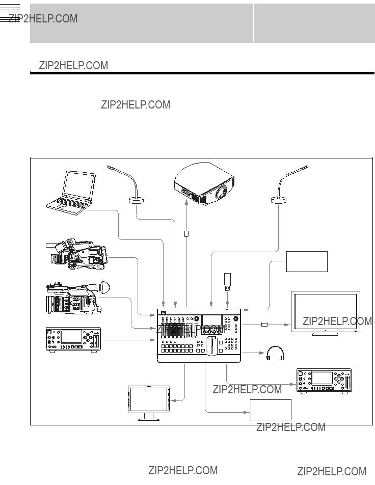
System configuration example: Live recording / production system (HD system)
For details on configurations for SD or 3D systems, see ???System Configuration Examples??? (c Advanced Settings).

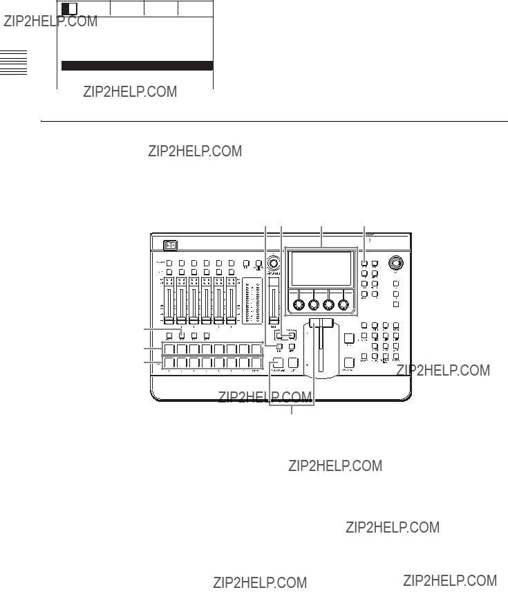
Names and Functions of Parts
Front Panel
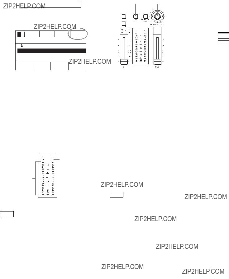
1 Audio Control Block
aACCESS/PFL
(page
bCH ON (channel on) buttons (page
dMONITOR SEL (monitor select) button
eMONITOR LEVEL adjustment knob (page
gInput signal indicator (page
Names and Functions of Parts
Overview 1 Chapter
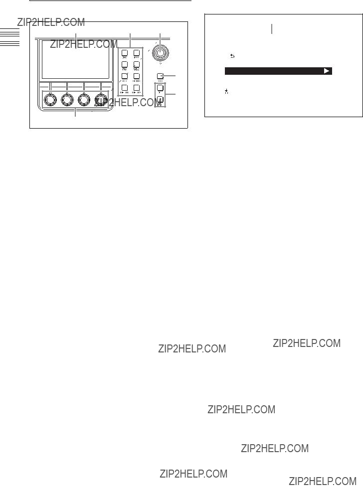
2 Menu Control Block
aMenu display
bMenu selection buttons
Display a menu that corresponds with the button pressed.
Displays the [Key] menu. (c Advanced Settings)
???EFF (effect) button
Displays the [Effect] menu. (c Advanced Settings)
???FM (frame memory) button
Displays the [Frame Memory] menu. (c Advanced Settings)
???MISC (miscellaneous) button
Displays the [Misc] menu. (c Advanced Settings)
???FILE button
Displays the [File] menu. (c Advanced Settings)
???SETUP button (pages
Displays the [Setup] menu. (c Advanced Settings)
???MENU1 and 2 buttons (for future expansion)
dPOS (position) button (c Advanced Settings) eF1 and F2 buttons (for future expansion)
Viewing the menu screen
aEffect pattern area (page
Displays the effect pattern icon and number currently selected for the effect transition.
bTransition rate area (page
Displays the transition rate of the current effect transition.
dAudio monitor area (page
eMenu name area
Left: Displays the name of the current menu.
Right: Displays the item number of the currently selected menu item or a message (c Advanced Settings).
fItems area
Displays the menu items.
gParameters area
Displays the parameter names and setting values.
Menu operations
When you press a menu selection button or an ACCESS/ PFL button, setting items and values appear in the parameters area at the bottom of the screen. You can use the corresponding adjustment knobs to perform adjustments and selections.
Basic adjustment knob operations
Items area
Turn the V1 knob left or right to move the cursor up or down.
If the B icon appears for an item, pressing the V1 knob moves to the sub menu of that item.
Parameters area
Turn the V2 to V4 knobs left or right to increase, decrease, or cycle through setting values.
You can make incremental adjustments to parameters in the [Effect] menu, [Key] menu (excluding some parameters in the [Resizer] menu), and the [Misc] menu that include decimal number values by turning the knobs while pressing them.
If an action (saving, applying of setting values, etc.) is associated with the respective item, pressing the knob performs this action.
3
aBus delegation buttons
(c Advanced Settings)
???BKGD (background) button (page
???KEY button (pages
???AUX 1 and 2 (auxiliary) buttons
(c Advanced Settings)
bPGM (program)
cPST/KEY (preset/key)
4 Transition Control Block
aTransition type selection buttons
???MIX button (pages
???EFF (effect) button (pages
bNext transition selection buttons
???BKGD (background) button (page
???KEY button (pages
cFTB
When you press the FTB button, the current program output image will fade out to a black screen. When you press the FTB button again, the original image will fade in from the black screen.
dAUTO TRANS
Overview 1 Chapter
Names and Functions of Parts
Overview 1 Chapter
hKEY TRANS (key transition) button
(c Advanced Settings)
Using the next transition selection buttons
Turn on (i.e., light) the buttons by pressing them to specify which part of the video is switched at the next transition.
When the AUX 1 or AUX 2 button is selected (i.e., lit) in the bus delegation buttons, the next transition is fixed at BKGD.
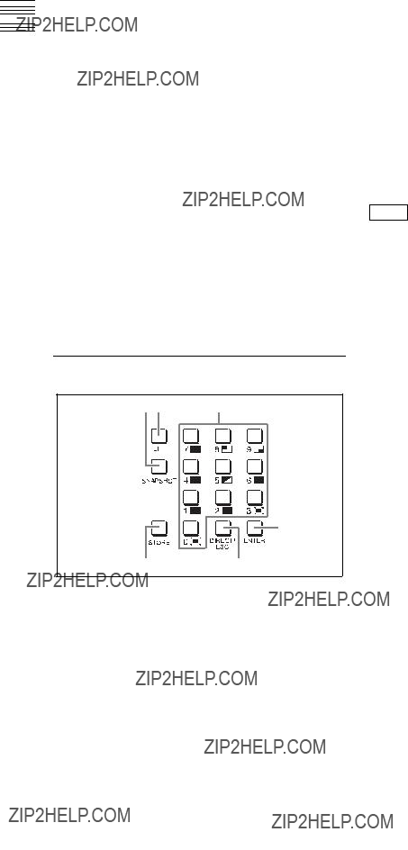
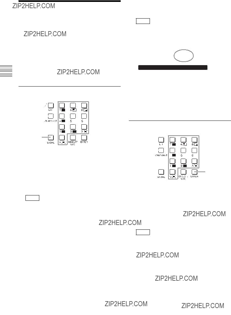
5 Numeric Keypad Block
12 3
4
56
aSNAPSHOT button (page
cNumeric buttons (0 to 9) (page
Entering numeric values
The numeric buttons are used to enter numeric values for operations such as specifying effect pattern numbers and saving or recalling snapshots.
1 Press the EFF button or SNAPSHOT button to light it.
(When specifying an effect pattern number, be sure to turn off the DIRECT/ESC button.)
2 Press the numeric buttons (0 to 9) to enter the numeric value.
The entered value appears in white at the top of the menu screen.
3 Press the ENTER button to confirm.
The numeric value appears in orange after it is confirmed.
Tip
If you press the DIRECT/ESC button before pressing the ENTER button after entering the numeric value, the value will be canceled.

Rear Panel
Connect a commercially available
bUSB connector
Connect a USB flash drive here.
cAC IN (power input) connector (page
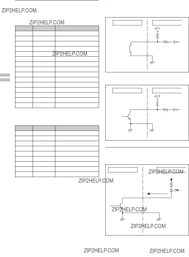
dTALLY/GPI connector
eREMOTE connector
fGround connector
Connect the system grounding wire here.
1 Audio Output Block
aHEADPHONES connector (standard stereo phone) (page
bMON OUT (monitor output) L and R connectors (TRS phone) (page
cMIX OUT (mix output) L and R connectors (phono jack) (c Advanced Settings)
dAUX OUT (auxiliary output) 1 and 2 connectors (TRS phone)
(c Advanced Settings)
ePGM OUT (program output) L and R connectors (XLR, male) (page
2 Audio Input Block
aLINE IN (line input) 7 and 8 connectors (phono jack) (page
bMIC/LINE IN (microphone/line input) 3 to 6 connectors (TRS phone) (page
cMIC/LINE IN (microphone/line input) 1 and 2 connectors (XLR, female/TRS phone combo)
These do not supply power (e.g., for condenser microphones).
Names and Functions of Parts

aVIDEO OUT AUX (video output auxiliary) connector (BNC type) (c Advanced Settings)
This output is used for confirming video.
b
???MULTI VIEWER connector (page
???AUX (auxiliary) connector
(c Advanced Settings)
Outputs 1080i/59.94, 1080i/50, 720p/59.94, and 720p/50 signals.
cSDI OUT (SDI output) connectors (BNC type)
???MULTI VIEWER connector (page
???AUX (auxiliary) 1 and 2 connectors
(c Advanced Settings)
???PGM (program) connector (page
4 Reference Signal Input/Output
Block
1
2
aREF OUT (reference signal output) connector (BNC type) (c Advanced Settings)
bREF IN (reference signal input) connectors (BNC type)
Input an external reference sync signal here. One of the connectors can be used as a
connector. If you will not be using

PreparationsChapter2
Connecting Devices
Connect each device to the rear panel of the unit.
Connection example: HD system
Preparations 2 Chapter
Preparations 2 Chapter
Notes
???When you are using a reference signal generator, and do not want to perform
signal input to one of the REF IN connectors of the unit, attach a 75 ?? terminator to the other connector (see page
???When the unit is connected to a device that cannot input external reference signals, you can enable synchronization by enabling the frame synchronizer function of the SDI input connector connected to the device (default: enabled). For details on configuration, see the ???Operating Instructions (c Advanced Settings).??? This is always enabled for the VIDEO IN 1 to 3 connectors.
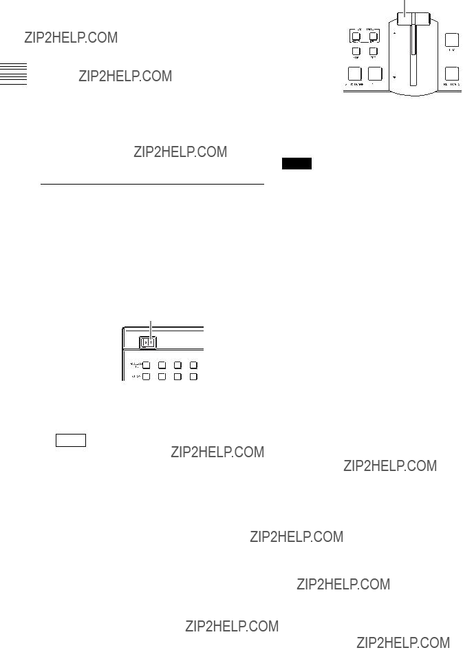
Turning the Unit On/Off
Turning the unit on
1 Connect the power cord (sold separately) to the AC IN connector on the rear panel of the unit, and connect the other end of the cord to an AC power supply.
2 Set the power switch to the ? position.
Power switch
The unit turns on and starts up.
After startup is complete, a menu screen appears in the menu display and the unit is ready for operations.
Tip
The [Misc] (miscellaneous) menu appears after startup is complete.
3 Raise or lower the fader lever all the way up or down.
Fader lever
Turning the unit off
Set the power switch to the a position.
Note
When you turn off the unit, the configurations for the current effects, keys, and setup are not saved. To save the current configurations, perform [Startup Define] in the [Setup] menu.
For details on this operation, see ???Saving Settings??? (page

Configuring System
Settings
Configure the system mode, system date and time, and other system settings in the menu control block.
For details on operations, see ???Menu operations??? (page
Configuring the Signal Format and
Aspect Ratio
Specify the image signal format and aspect ratio to be used by the unit.
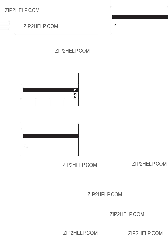
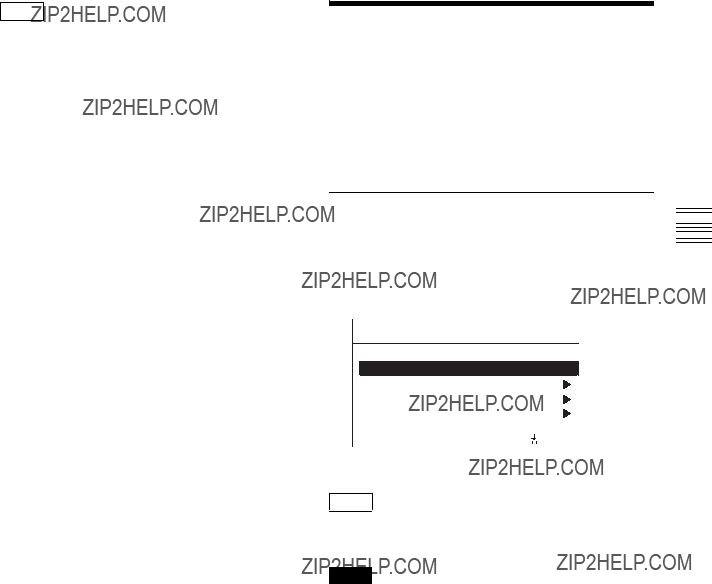
1 Press the SETUP button to display the [Setup] menu.
2 Turn the V1 knob to select [System], and press the knob.
Startup Define
System
Audio
Video (Input)
S e l e c t
 Enter
Enter
3 Turn the V1 knob to select [System Format], and select the signal format and aspect ratio with the respective knobs.
Notes on setting values 108059: 1080i/59.94 (HD mode) 108050: 1080i/50 (HD mode) 720p59: 720p/59.94 (HD mode) 720p50: 720p/50 (HD mode) 480i59: 480i/59.94 (SD mode) 576i50: 576i/50 (SD mode) Test1: Used for tests.1)
Test2: Used for tests.
Test3: Used for tests.
1)When [Test1] is selected while VGA signals (640 ?? 480/ 59.94p, 60p) are input to HDMI IN 1 to 3, and you select HDMI inputs 1 to 3 using the PGM
Note
Under normal circumstances, do not use the Test1 to Test3 settings as they are intended for tests. Functioning and performance are not guaranteed if you use Test1 to Test3.
4 Press the V3 or V4 knobs.
A confirmation message appears.
5 Press the V3 knob.
OK
The confirmation message disappears.
6 Turn off the unit and turn it on again.
The unit will restart with the specified signal format and aspect ratio applied.
Preparations 2 Chapter
Preparations 2 Chapter
Notes
???When the signal format is set to an HD mode, the 4:3 aspect ratio cannot be selected.
???To save effects, keys, and other setup configurations, perform [Startup Define] in the [Setup] menu before turning off the unit (see page
???If you want to configure other settings that require a system restart, configure all of the settings before restarting the unit.
Configuring the Date and Time
Configure the unit???s internal clock.
1 Press the SETUP button to display the [Setup] menu.
2 Turn the V1 knob to select [System], and press the knob.
Startup Define
System
Audio
Video (Input)
S e l e c t
 Enter
Enter
3 Turn the V1 knob to select [Date], and set the date with the respective knobs.
4 Press the V2, V3, or V4 knobs.
5 Turn the V1 knob to select [Time], and set the clock with the respective knobs.
6 Press the V3 or V4 knobs.

Configuring Video Signal
Settings
Configure settings for handling video signals on the unit.
Assigning Video Signals to the
Assign the video signals that are input to the video input connectors on the rear panel of the unit and the unit???s internal signals to
Only signals of the format that is specified under [System Format] in the [Setup] menu can be input for SDI 1 to 4, HDMI 1 to 3, and VIDEO 1 to 3.
1 Press the SETUP button to display the [Setup] menu.
2 Turn the V1 knob to select [Video (XPT)], and press the knob.
Audio
Video (Input)
Video (XPT)
Video (Output)
S e l e c t
 Enter
Enter
3 Turn the V1 knob to select the number of the
Notes on setting values
Black: Black video
SDI1 to 4: Video input from the SDI IN 1 to 4 connectors
DVI: Video input from the
H/V1 to 3: Video input from the HDMI IN 1 to 3 connectors or VIDEO IN 1 to 3 connectors
ColBg: Color background video
FM: Frame memory video
PGM: Program video output
4 Repeat step 3 for assignments to other buttons.
Preparations 2 Chapter

Preparations 2 Chapter
Tip
The following assignments are set under factory default settings.
Configuring the Format of the Signal Input to the
To use DVI video inputs, configure the format of the signal input to the
1 Press the SETUP button to display the [Setup] menu.
2 Turn the V1 knob to select [Video (Input)], and press the knob.
Audio
Video (Input)
Video (XPT)
Video (Output)
S e l e c t
 Enter
Enter
3 Turn the V1 knob to select [DVI], turn the V3 knob to select the signal format, and press the knob.
Notes on setting values
XGA: Analog, 1024 ?? 768/60
SXGA: Analog, 1280 ?? 1024/60
WXGA: Analog, 1280 ?? 768/60
HDTV50: Digital, 1080p/50
HDTV60: Digital, 1080p/60
Note
Digital signals are not accepted (i.e., not supported) in 720p/59.94, 720p/50, 480i/59.94, or 576i/50 mode.
Configuring Audio Signal
Settings
Configure settings for handling audio signals on the unit.
Assigning Audio Input Signals to the Channel Faders
Assign the audio signals that are input to the audio input connectors on the rear panel of the unit to the channel faders (1 to 6).
Assigning separate audio to the left and right channels (L/ R) of a fader creates a stereo fader, while assigning the same audio to the left and right channels creates a monaural fader.
Audio input signals
1 Press the SETUP button to display the [Setup] menu.
2 Turn the V1 knob to select [Audio], and press the knob.
Startup Define
System
Audio
Video (Input)
S e l e c t
 Enter
Enter
3 Turn the V1 knob to select the channel fader number ([Audio Input Assign 1] to [Audio Input Assign 6]) to which you want to assign the audio signal, and select the audio signals for L and R with the respective knobs.
4 Repeat step 3 for assignments to other channel faders.
Tip
The following assignments are set under factory default settings.
Preparations 2 Chapter

Preparations 2 Chapter
Configuring the Mic/Line Levels for Audio Inputs
Adjustment of mic/line levels is necessary when the peak indicators light red, or when the input signal indicators do not light while audio signal input exists.
Peak indicator
Input signal indicator
When the peak indicators light red
A channel fader???s peak indicator will light red if the audio signal input is too loud. In this case, since the analog mic/ line level exceeds the input level of the currently selected line, use the following procedure to adjust it.
1 Press the SETUP button to display the [Setup] menu.
2 Turn the V1 knob to select [Audio], and press the knob.
Startup Define
System
Audio
Video (Input)
S e l e c t
 Enter
Enter
3 Turn the V1 knob to select the number of the MIC/ LINE IN connector ([MIC/LINE 1 Level] to [MIC/ LINE 6 Level]) for which you want to configure the mic/line level, and turn the V4 knob to select the level.
4 Repeat step 3 to configure the levels for the other MIC/ LINE IN connectors.
Setting example:
If a peak indicator lights at the default setting of
When the input signal indicators do not light
When the input signal indicators do not light even when audio signals are being input, the reference values for the mic/line levels are not being met. In such cases, perform the previous peak indicator procedure, and configure the lower mic/line levels for the respective channels.
Setting example:
If an input signal indicator does not light at the default setting of

Configuring Multi Viewer
Settings
The Multi Viewer allows you to display multiple video inputs, program video outputs, and preview video outputs simultaneously on a monitor connected to the unit. A
(The numbers indicate the number assignments for each
Multi Viewer output example:
Red frames indicate the
Red frame
Note
If a frame memory key is on air, the red frame appears in the
When using the Multi Viewer, specify the video output for each
1 Press the SETUP button to display the [Setup] menu.
2 Turn the V1 knob to select [Multi Viewer], and press the knob.
Video (Misc)
Multi Viewer
GPI/Tally
Information
S e l e c t
 Enter
Enter
3 Turn the V1 knob to select [Viewer Mode], and turn the V4 knob to select the
4 Turn the V1 knob to select the
Preparations 2 Chapter

Preparations 2 Chapter
Notes on setting values
Black: Black video
SDI1 to 4: Video input from the SDI IN 1 to 4 connectors
DVI: Video input from the
H/V1 to 3: Video input from the HDMI IN 1 to 3 connectors or VIDEO IN 1 to 3 connectors
ColBg: Color background video
PGM: Program video output
PVW: Preview video output
Aux1PG: Program video output of the Aux1 bus
Aux1PV: Preview video output of the Aux1 bus
Aux2PG: Program video output of the Aux2 bus
Aux2PV: Preview video output of the Aux2 bus
5 Repeat step 4 to configure the other
Tip
The following video signals are assigned to each

Basic Operations
Switching Video
Switch between video signals that are input to the unit, compose images, and output programs from the PGM output connector.
This section describes simple operations for switching video and applying effects while switching.
Frequently used effects can be saved as ???snapshots??? and recalled when necessary. For details, see ???Snapshots??? (page
This is the most basic form of switching. Switching between video A and video B occurs instantly without added effects.
AB
You can cut between videos by pressing a PGM
1 In the
The button you pressed lights red, and the video is output as the program output.
Chapter3
PGM
the current program video output.
2 Determine the next video to be used for program output, and press the corresponding PGM
The program video switches.
Checking the Preview Video before Switching with the CUT Button
Preview the next video that will be used for the program output before switching.
1 In the
The PGM
2 Press the PST/KEY
The PST/KEY
Switching Video
Operations Basic 3 Chapter
3 Press the CUT button in the transition control block.
The program video interchanges with the preview video.
The lit PGM
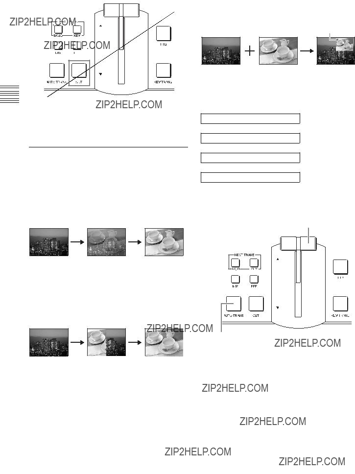
Applying Effects while Switching (Mix/Effect)
Instead of an instantaneous cut, you can gradually switch from one video to another through the various effects.
Transition into the next video by gradually overlapping the existing image.
Effect
You can use Wipe, NAM
With this effect, the next video for output replaces the current program video output as if wiping it away.
Example: Frame In/Out (page
With this effect, the next video is superimposed as a frame within the current program video output and gradually expands to replace the current video.
Superimposed frame
Multiple patterns may be available for certain effects. For details on the different patterns, see ???Effect Pattern List??? (page
Basic operation flow
Select the video for program output.
r
Select the next video for output.
r
Select an effect (mix/effect).
r
Execute the transition.
To execute the transition
Press the AUTO TRANS button in the transition control block, or operate the fader lever.
Fader lever
AUTO TRANS button
AUTO TRANS button (automatic execution)
The video switches automatically at the current speed (transition rate) setting.
You can change the transition rate under [Transition Rate (1/2)] in the [Misc] menu. For details on configuration, see ???Configuring the Transition Rate??? (page

Keypad (Direct Selection)
3 Press the MIX button in the transition control block.
The following effect patterns are
These buttons make it easy for you to apply effects.
Operations Basic 3 Chapter
You can change the rate at which a video switches over (i.e., transition rate) when the AUTO TRANS button is used to execute a transition.
1 Press the MISC button to display the [Misc] menu.
2 Turn the V1 knob to select [Transition Rate (1/2)], and configure the transition rate with the V2 knob.
1 Press the PGM
2 Press the PST/KEY
Switching Video

3 Select an effect in the numeric keypad block.
13
1 Press the EFF button to light it.
Specifying effects by pattern number
Perform the following to specify effects by entering effect pattern numbers.
For details on pattern numbers, see ???Effect Pattern List??? (page
1 Press the EFF button in the numeric keypad block to light it.
2 If the DIRECT/ESC button is lit, press the button to turn it off.
3 Use the numeric buttons (0 to 9) to enter the pattern number.
The pattern number entered appears at the top left of the menu screen.
4 Press the ENTER button.
The pattern icon of the number entered appears, and the effect pattern number changes to an orange display.
Tip
If you press the DIRECT/ESC button before pressing the ENTER button after entering the pattern number, the entry will be canceled and revert to the original pattern number.
Composing Images with Keys
Keying is a function in which part of the background image is replaced by another image or superimposed text. The following keys can be used with this unit to compose video.
Based on the brightness (luminance) of the key source1), key fill1) image B is cut out and superimposed on image A (i.e., the background).
In this composition example, the same image is selected as the key source and key fill.
1)The signal for cutting out the background is called a key source, and the signal for filling the cutout portion is called a key fill.
Linear key
This is a type of luminance key with a reduced variability in gain that allows more precise adjustment.
For details on operations, see ???Making Detailed Adjustments to the Linear Key??? (c Advanced Settings).
A particular color (chroma) component is removed from image B, and image B is superimposed on image A (i.e., the background). Typically, a subject is shot in front of a blue screen and the portions of the background that contain blue components are later removed, leaving only the subject to be superimposed.

Composing Images with Luminance Keys
8
If necessary, you can also configure the clip value (brightness), gain value, and key transparency.
For details on configuration, see ???Making Detailed Adjustments to the Luminance Key??? (c Advanced Settings).
8 Execute the transition.
The image of the PST/KEY
You can also configure the duration for video composition (transition rate). For details on configuration, see the ???Configuring the Transition Rate??? (page
Luminance key settings can be saved as ???snapshots??? and recalled when necessary. For details, see ???Snapshots??? (page
Operations Basic 3 Chapter
Selecting the key fill and key source separately
Perform the following between step 7 and 8 of the previous procedure.
1Turn the V1 knob to select [Key Fill/Src Select], and turn the V3 knob to select [Split].
Rate SS Mon
2Press the PST/KEY
Basic 3 Chapter
Operations
Composing Images with Chroma Keys
This section describes how to perform ???auto chroma key??? where you specify a portion of the foreground video (e.g., a blue background color) and use it as a reference signal for creating the chroma key image through automatic adjustment.
You can also adjust chroma keys manually (manual chroma key). For details, see ???Making Detailed Adjustments to the Chroma Key??? (c Advanced Settings).
1 Press the KEY bus delegation button.
2 Press the PGM
3 Press the PST/KEY
12
4
5
Press the KEY next transition selection button.
The selected image in its ???key on??? state is used for PVW output.
Press the MIX button or EFF button.
6 Press the KEY button in the menu control block to display the [Key] menu.
7 Turn the V1 knob to select [Key Type Select], and turn the V4 knob to select [Chr].
8 Turn the V1 knob to select [Key Fill/Src Select], and turn the V3 knob to select [Self].
9 Turn the V1 knob to select [Chromakey Auto Adj], and press the knob.
The menu changes to the [Auto Chromakey] menu for automatic chroma key adjustment.
10Turn the V1 knob to select [Sample Mark], and press the V4 knob.
Auto chroma key mode is enabled, and a white sample mark appears in the PVW image.

 Sample mark
Tip
To disable auto chroma key mode, press the V4 knob again.
11Turn the V1 knob to select [Sample Mark Adjust], and turn the respective knobs to move the sample mark to specify the color to remove (i.e., the reference signal for the chroma key).
You can adjust the size and position of the sample mark using the following knob operations.
1) The setting range will vary depending on the size setting.
Operations Basic 3 Chapter

Operations Basic 3 Chapter
12Turn the V1 knob to select [Auto Adjust Execute], and press the V4 knob.
Auto chroma keying is executed using the color specified with the sample mark as a reference signal, and the composed image is output in the PVW area.
Tip
After the auto chroma keying is executed, the sample mark disappears automatically.
13Execute the transition.
The image of the PST/KEY
You can also configure the duration for video composition (transition rate). For details on configuration, see the ???Configuring the Transition Rate??? (page
Chroma key settings can be saved as ???snapshots??? and recalled when necessary. For details, see ???Snapshots??? (page
Mixing Audio
Mix audio that is input to the unit, and output the final audio (i.e., program output) from the PGM OUT connector of the audio output block.
Input signals must be assigned to the channel faders (1 to 6) in the audio control block beforehand. For details on configuration, see ???Assigning Audio Input Signals to the Channel Faders??? (page
1
1 In the audio control block, press the CH ON buttons for the channels to which the audio signals you want to mix are assigned to light them.
The button lights green or turns off with each press.
CH ON button status
2 Adjust the audio levels using each channel fader to perform mixing.
3 Use the program fader to adjust the audio level of the program output.
If the peak indicators light red or the input signal indicators do not light, see ???Configuring the Mic/Line Levels for Audio Inputs??? (page
Switching audio for monitoring
Press the MONITOR SEL button to select [PGM].
The button lights orange for a moment and the audio for monitoring switches in the following sequence with each press.
PGM t AUX1 t AUX2 t MIX
R
The current selection appears at the top right of the menu screen.
Audio for monitoring
PGM: Audio output from the PGM OUT L and R
connectors
AUX1: Audio output from the AUX OUT 1 connector
AUX2: Audio output from the AUX OUT 2 connector
MIX: Audio output from the MIX OUT L and R
connectors
Adjusting audio levels for monitoring
Use the MONITOR LEVEL adjustment knob and the DIM button to adjust the level of the audio that is output to devices connected to the MON OUT L and R connectors and the HEADPHONES connector.
MONITOR LEVEL adjustment knob
Turn the knob to perform adjustment of the audio level for monitoring.
DIM button
Pressing the button lights it orange and enables the dimmer function, which lowers the monitor level 20 dB. Pressing the button again disables the dimmer function and returns the original monitor level.
Operations Basic 3 Chapter
Viewing the audio level meters
The audio level meters display the levels of the audio selected with the MONITOR SEL button within a 0 dB to
Over level display
Lights red when the level reaches 0 dB.
Each level lights green as it is exceeded.
 The lowest level,
Tips
???Peak hold is performed.
???During PFL
Monitoring the Audio of a Particular
Channel Only
Use the
Hold down the ACCESS/PFL button for the channel you want to monitor for at least 0.5 seconds. While the button is held down, the audio for that channel is monitored.
When you release the ACCESS/PFL button, the monitoring is ended.
Tips
???If you press another ACCESS/PFL button for at least 0.5 second during PFL, the sound of the subsequently specified channel is added.
???This does not affect the program output, AUX output, or MIX output.
Mixing Audio
Operations Basic 3 Chapter
Snapshots
The snapshot function allows you to save effect and key settings for specific scenes. By saving frequently used settings as snapshots, you can quickly recall settings when necessary. Up to 20 snapshots can be saved.
The following information is stored in a snapshot.
???
???Backgrounds/keys
???Effect patterns
???Key setting status
???Transition status
Saving Snapshots
1


 2
2
3
1 Press the SNAPSHOT button in the numeric keypad block to light it.
2 Use the numeric buttons to enter the number (1 to 20) under which to save the snapshot.
The number entered appears as the snapshot number in the menu screen.
Tip
If a snapshot is not currently registered to the number entered, ???E??? (empty) will appear to the left of the number.
3 Press the STORE button.
The snapshot is registered.
Tip
If you enter a number that is already in use, the previous snapshot will be overwritten.
Example: When registered to number 8
Snapshots can be exported to and imported from USB flash drive. For details on operations, see ???Importing Snapshots??? (c Advanced Settings).
Recalling Snapshots
1


 2
2
3
1 Press the SNAPSHOT button in the numeric keypad block to light it.
2 Use the numeric buttons to enter the number of the snapshot to recall.
The number entered appears as the snapshot number in the menu screen.
Tip
If a snapshot is not currently registered to the number entered, ???E??? (empty) will appear to the left of the number.
3 Press the ENTER button.
The snapshot is recalled.
Tip
To recall a snapshot without changing the
Saving and Selecting
Settings
You can save the current settings for effects, keys, and setup.
You can also select whether to start up the unit with the saved settings or with the factory default settings.
Saving Settings
1 Press the SETUP button to display the [Setup] menu.
2 Turn the V1 knob to select [Startup Define], and press the V4 knob.
The effect, key, and setup settings are saved.
Tip
When settings are saved, the [Startup Mode] automatically changes to [User].
Note
The current settings will be lost if the unit is turned off without saving.
Operations Basic 3 Chapter

Operations Basic 3 Chapter
Selecting the Settings Recalled at
Startup
1 Press the SETUP button to display the [Setup] menu.
2 Turn the V1 knob to select [System], and press the knob.
Startup Define
System
Audio
Video (Input)
S e l e c t
 Enter
Enter
3 Turn the V1 knob to select [Startup Mode], turn the V4 knob to select the mode, and press the knob.
Notes on setting values
Fact: Factory default settings
User: Saved settings

Appendix
Effect Pattern List
Wipe
Mix
900 MIX
Squeeze
Appendix
Defocus1)
1702
1) Can only be used for BKGD transitions.

Troubleshooting
Please verify the problem again. If the problem persists, contact your local Sony representative.


Supported input formats
??? HD/SD system
1) WXGA (1280 ?? 768) supports only the following formats.
??? 3D system (Single, Dual Stream)
Supported output formats
??? HD/SD system
??? 3D system (Single, Dual Stream)
1) MV: MULTI VIEWER
Audio signals
Audio input
Analog input 1 and 2
XLR+TRS combo (2) (MIC/LINE 1 and 2), male
Reference input level:
Analog input 3 to 6
TRS phone (4) (MIC/LINE 3 to 6) Reference input level:
+4 dBu, input impedance: 3.3 k?? or more
Analog input 7 and 8
Phono jack (2) (LINE 7 and 8) Reference input level:
input impedance: 10 k?? or more
Audio output
Analog output 1 and 2
Headphones output
Standard stereo PHONE (1)
Max. output: 25 mW ?? 2 (16 ?? load)
Other interfaces
Supplied accessories
Operating Instructions (Volume I Basic Operation) (Japanese and English, 1 each) (this document)
Warranty (1)
Optional accessories
1 AC power code (for USA and Canada)
125 V, 10 A, 2.4 m (7 ft. 10 1/2 in.) Part number:
1 AC power code (for Europe)
250 V, 10 A, 2.5 m (8 ft. 2 1/2 in.) Part number:
1 AC power code (for China)
250 V, 10 A, 1.83 m (6 ft. 1/2 in.) Part number:
2 Holder, Plug (Black)
Part number:
Design and specifications are subject to change without notice.
???Always make a test recording, and verify that it was recorded successfully.
SONY WILL NOT BE LIABLE FOR DAMAGES OF
ANY KIND INCLUDING, BUT NOT LIMITED TO,
COMPENSATION OR REIMBURSEMENT ON
ACCOUNT OF FAILURE OF THIS UNIT OR ITS
RECORDING MEDIA, EXTERNAL STORAGE
SYSTEMS OR ANY OTHER MEDIA OR STORAGE
SYSTEMS TO RECORD CONTENT OF ANY TYPE.
???Always verify that the unit is operating properly before use. SONY WILL NOT BE LIABLE FOR
DAMAGES OF ANY KIND INCLUDING, BUT
NOT LIMITED TO, COMPENSATION OR
REIMBURSEMENT ON ACCOUNT OF THE LOSS
OF PRESENT OR PROSPECTIVE PROFITS DUE
TO FAILURE OF THIS UNIT, EITHER DURING
THE WARRANTY PERIOD OR AFTER
EXPIRATION OF THE WARRANTY, OR FOR
ANY OTHER REASON WHATSOEVER.
Appendix
Specifications

Index
Numerics
3D Mode
3D System
A
ACCESS/PFL Button
Incremental Adjustment
Audio
Audio Channel Menu
Input Trim
PGM Assign
Audio Level Meters
Audio Input Assign
Audio Output Delay
Output Level
SDI OUT AUX Assign
SDI OUT MULTI VIEWER Assign
SDI OUT PGM Assign
Audio Monitor
Auto Adjust Execute
Auto Adjust Execute
AUX OUT Assign
B
Border Adjust
Border Matte Adjust
Bus Delegation
AUX 1 and 2 Buttons
BKGD Button
KEY Button
C
D
DME Wipe Modify Menu
Crop H
Crop V
Positioner
Positioner Adjust
Size
DVI Input Signals
DVI OUT AUX Assign
DVI OUT MULTI VIEWER
Assign
E
EFF Button
Effect Menu
DME Wipe Adjust
DME Wipe Bkgd Color
DME Wipe Edge
DME Wipe Edge Color
Effect Transition
Wipe Adjust
Wipe Edge
Wipe Edge Color
Effect Transition
Equalizer
Equalizer High
Equalizer Low
Equalizer Mid
Export
Export Config
Export Snapshot
Exporting
Configuration Data
Frame Memory
Snapshot
F
Fade To Black
FILE Button
File Menu
Export Config
Export Snapshot
Import Config
Import Snapshot
USB Memory Format
Fine Key
Fine Key Adjust H
Index
Index

Index
M
Manual Chromakey Menu
Chr Key Adjust
Chr Key Window
Chr Key Window Adj
Color Cancel
Color Cancel Adjust
Menu
EFF Button
FILE Button
KEY Button
MISC Button
SETUP Button
Message List
MIC/LINE Level
MISC Button
Misc Menu
Color BKGD
Port Enable
Transition Rate
MIX OUT Assign
Multi
Multi Adjust
N
Next Transition Selection Button

O
On Air Source
Oscillator
Output Level
P
Pan
PGM Assign
Port Enable
POS Button
Positioner
Positioner Adjust
R
REF OUT Phase
Resizer
Resizer Menu
Aspect
Location
Rotation
Rotation Mode
Rotation
Rotation Adjust
Rotation Mode
S
Sample Mark
Sample Mark Adjust
SDI
SDI OUT AUX Assign
SDI OUT MULTI VIEWER
Assign
SDI OUT PGM Assign
Select
Setup
Setup Menu
Audio
GPI/Tally
Information
Install
System
Video (Input)
Video (Misc)
Video (Output)
Video (XPT)
SHIFT
Size
Startup Mode
System Configuration Example
3D System
SD System
System Format
System Menu
3D Mode
Date
LCD Backlight
REF OUT Phase
Startup Mode
System Format
System Reference
Time
System Reference
T
Tally Output
Transition Indicator
Transition Rate
Transition Type
Transition Type Selection Button
U
USB Memory Format
V
VIDEO
Video (Input) Menu
DVI
HDMI
SDI
VIDEO
Video (Misc) Menu
Fade To Black
Switch Timing
Video (Output) Menu
DVI OUT AUX Assign
DVI OUT MULTI VIEWER
Assign
SDI OUT AUX Assign
SDI OUT MULTI VIEWER
Assign
SDI OUT PGM Assign
VIDEO
Video (XPT) Menu
XPT Assign
XPT Shift Mode
Video Switching
W
Wipe
Wipe Adjust
Wipe Edge
Wipe Edge Color
Wipe Modify Menu
Aspect
Multi
Multi Adjust
Positioner
Positioner Adjust
Rotation
Rotation Adjust
Wipe Patterns
X
XPT Assign
Index
Index
The material contained in this manual consists of information that is the property of Sony Corporation and is intended solely for use by the purchasers of the equipment described in this manual.
Sony Corporation expressly prohibits the duplication of any portion of this manual or the use thereof for any purpose other than the operation or maintenance of the equipment described in this manual without the express written permission of Sony Corporation.
Trademarks
HDMI, the HDMI logo and
Other products or system names appearing in this document are trademarks or registered trademarks of their respective owners.
Further, the ?? or ??? symbols are not used in the text.

Sony Corporation
Printed in China
