Multi Format
Compact Switcher
Operating Instructions (Volume II Advanced Settings)
Before operating the unit, please read this manual thoroughly and retain it for future reference.
Software Version 1.00
?? 2011 Sony Corporation
Multi Format
Compact Switcher
Operating Instructions (Volume II Advanced Settings)
Before operating the unit, please read this manual thoroughly and retain it for future reference.
Software Version 1.00
?? 2011 Sony Corporation

Table of Contents
(this manual)

Table of Contents
(Volume I Basic Operation)
Chapitre 1 Overview
Introduction
Names and Functions of Parts
Chapitre 2 Preparations
Connecting Devices
Configuring System Settings
Configuring Video Signal Settings
Configuring Audio Signal Settings
Configuring Multi Viewer Settings
Chapitre 3 Basic Operations
Switching Video
Composing Images with Keys
Mixing Audio
Snapshots
Saving and Selecting Settings
Appendix
Effect Pattern List
Troubleshooting
Maintenance
Specifications
Index

About This Manual
This manual describes how to make adjustments and settings to enable you to use the advanced features of this unit.
For the basic operating procedures of the unit, see to ???Operating Instructions (Volume I Basic Operation).???
How to View This Manual
About setting values
The setting values shown in bold are the factory default settings.
Examples:
About references
References to the Operating Instructions (Volume I Basic Operation) are indicated by the c mark as follows.
Example 1:
Channel faders (c Basic Operation: ???Names and Functions of Parts???)
Example 2:
For details, see ???Effect Pattern List??? (c Basic Operation).
To find information on a specific topic
See ???Index??? (page
The index indicates whether the information can be found in ???Volume I Basic Operation??? or ???Volume II Advanced Settings??? and the corresponding page numbers.
Overview
Introduction
Chapter1
Overview 1 Chapter
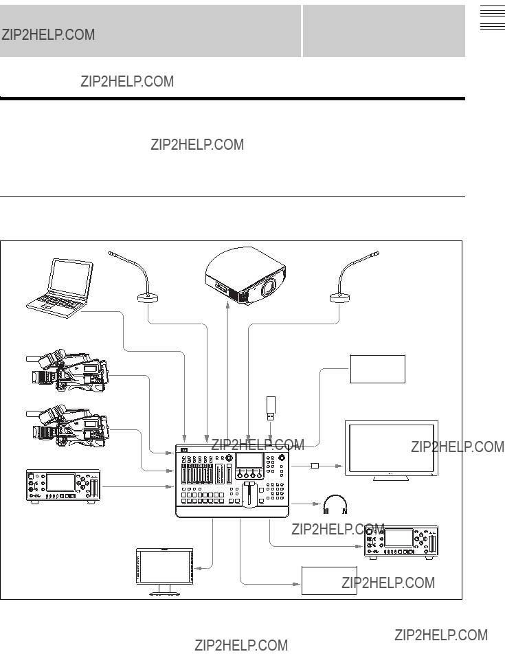
The unit allows you to adjust and set video effects, transitions, and audio in detail to perform more sophisticated switching. You can also perform 3D video switching, and use the frame memory function to write one screen of the input video to memory so that you can use it as input material.
System Configuration Examples
Example 1: When SD system

For details on configurations for 3D systems, see ???Chapter 6: 3D System??? (page

Overview
This unit allows you to apply various effects when switching video, and compose images using keys. Adjustments and configurations during video switching are performed from the following menus.
In addition, this unit includes three video composition blocks, M/E (Mix/Effect), Aux1, and Aux2. By using Aux1 or Aux2, you can mix video (PGM) created with M/ E (Mix/Effect) with another video.
For details, see ???Bus Delegation??? (page
Setting the Transition
Type
You can specify the transition type that is used when you perform effect transitions.
You can select any of the following transition types. Wipe: Use a wipe to switch from the current output image
to a new image.
NAM
For the first half of the transition, the current image is maintained at 100% and NAM is gradually performed for the new image. At the halfway point, NAM is performed for both images which are maintained at 100%. In the second half, the new image is maintained at 100% and NAM is performed while the current image is gradually reduced.
DME (Digital Multi Effects): Use DME effects to switch the image currently being output in a manner that appears as if it is being wiped (DME wipe).
Switching Video 2 Chapter

Switching Video 2 Chapter
General Transition Settings ([Misc] menu)
You can set the transition rate and the color background (ColBg) with the items in the [Misc] menu. Press the MISC button in the menu control block to display the [Misc] menu.
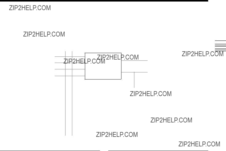
Bus Delegation
This unit includes three video composition blocks, M/E (Mix/Effect), Aux1, and Aux2. Each block includes four or two buses and can execute transitions.
However, Aux1 is dedicated to Aux1 PGM bus and Aux1 PST bus mixing, Aux2 is dedicated to Aux2 PGM bus and Aux2 PST bus mixing, and wipes, keys, and other effects cannot be added to either.
PGM Bus
Chapter
PST Bus
Preview
M/E
Key Fill Bus(Mix/Effect)
Program
Key Source Bus
Switching Video 2
Using the Bus Delegation Buttons
Turn on (i.e., light) one of the following buttons by pressing it to select the control objects for the
To select a key source
Press a PST/KEY
Mixing Video Created with M/E (Mix/ Effect) with Other Video
By using Aux1 or Aux2, you can mix video (PGM) created with M/E (Mix/Effect) with another video.
This section describes the procedure for using Aux1 as an example.
Preliminary settings
1 Select the Aux1 program as the program video output.
Settings menu: [Setup] menu > [Video (Output)] menu (page
2 Set Aux1 as the reference signal for the
Settings menu: [Setup] menu > [GPI/Tally] menu > [On Air Source] (page

Switching Video 2 Chapter
Mixing operation
1
2
3 Select the signal you want to mix in the PST/KEY
4 Execute the transition using the fader lever, CUT button, or AUTO TRANS button.
Tip
Aux1 and Aux2 settings are not stored in snapshots.
Setting Wipes
A wipe is a transition effect that switches to the next video by applying an effect that removes the program output video in a manner that appears as it is being wiped off with the video to be output next.
With this unit, you can make the following settings.
???Selecting the Pattern and Direction for Wipes (page
???Making Detailed Adjustments to Wipe Patterns (page
???Adding the Edge to the Wipe Pattern (page
This section describes wipe effects and basic operations for wipes.
Wipe settings are made in the [Effect] menu.
For details on the menu item, see ???Details on [Effect] Menu??? (page
Tip
The [Effect] menu does not appear in 3D mode.
Basic Operations for Wipe
Select the video for program output.
r
Select the next video for output.
r
Press the EFF transition type selection button.
r
Set the transition type to [Wipe].
r
Select the pattern and direction for the wipe.
r
Make detailed adjustments to the wipe pattern if necessary.
r
Execute the transition.
Selecting the Pattern and Direction for Wipes
A wipe can be set to proceed in either the normal wipe direction (normal) or reverse wipe direction (reverse). You can also specify normal and reverse to be switched each time a transition finishes (normal/reverse).
Selecting the wipe pattern
You can select the wipe pattern using one of the following three methods.
???Select from the patterns assigned to the numeric buttons (direct selection).
For details, see ???Selecting Effects with the Numeric Keypad (Direct Selection)??? (c Basic Operation)
??? Enter the pattern number with the numeric buttons.
For details, see ???Specifying effects by pattern number??? (c Basic Operation).
??? Specify the pattern number in the [Effect] menu.
Specifying the pattern number in the [Effect] menu
Settings menu: [Wipe Adjust] (page
For details on the wipe pattern numbers, see ???Effect Pattern List??? (c Basic Operation).
Setting the wipe position
The wipe position can be set in the [Wipe Modify] menu or with the
Setting the rotation method of a wipe pattern
You can select from the following three rotation methods for wipe patterns.
Angle
Performs the wipe with the pattern inclined at a fixed angle.
Speed
Rotates the pattern at a fixed speed during the transition.
Making Detailed Adjustments to Wipe Patterns
You can set the position of a wipe pattern and apply various variations and modifiers in the [Wipe Modify] menu.
To display the [Wipe Modify] menu
Display the [Effect] menu, turn the V1 knob to select [Wipe Adjust], and press this knob.
Setting Wipes

Setting the aspect ratio of a wipe pattern
You can freely change the aspect ratio of a wipe pattern.
Aspect Adjustment OffAspect Adjustment On
Furthermore, you can select from the following four methods for placing the patterns.
1:All of the patterns are oriented the same way
2:Even numbered rows are moved in the horizontal direction
3:Even numbered columns and even numbered rows are reversed
4:Even numbered columns and even numbered rows are reversed and even numbered rows are moved in the horizontal direction
Settings menu: [Wipe Modify] menu > [Multi]
Adding the Edge to the Wipe Pattern
You can add a border around the pattern (border), defocus the edge around the pattern (soft), and defocus an added edge of border (soft border).
The edge color can also be adjusted.
Border: You can adjust the width of the border.
Soft Edge: You can adjust the defocus condition for the edge.
Soft Border: You can adjust the width of the border and the defocus condition for the edge of the border.
Settings menu: [Wipe Edge] (page

Setting DME Wipes
DME wipes are effects that use DME (digital multi effects) to switch the image currently being output in a manner that appears as if it is being wiped.
With this unit, you can make the following settings.
???Selecting the Pattern and Direction for DME Wipes (page
???Making Detailed Adjustments to DME Wipe Patterns (page
???Adding an Edge to a DME Wipe Pattern (page
???Adjusting the Background Color of a DME Wipe (page
This section describes DME wipe effects and basic operations for DME wipes.
DME wipe settings are made in the [Effect] menu.
For details on the menu item, see ???Details on [Effect] Menu??? (page
Basic Operations for DME Wipe
Select the video for program output.
r
Select the next video for output.
r
Press the EFF transition type selection button.
r
Set the transition type to [DME].
r
Select the pattern and direction for the DME wipe.
r
Make detailed adjustments to the DME wipe pattern if necessary.
r
Execute the transition.
Selecting the Pattern and Direction for DME Wipes
For details on the pattern and direction for DME wipes, see ???Selecting the Pattern and Direction for Wipes??? (page
Making Detailed Adjustments to DME Wipe Patterns
You can adjust the position of a DME wipe pattern, adjust the size of the
To display the [DME Wipe Modify] menu
Display the [Effect] menu, turn the V1 knob to select [DME Wipe Adjust], and press this knob.
Setting the DME wipe position
The wipe position can be set in the [DME Wipe Modify] menu or with the
Settings menu: [DME Wipe Modify] menu > [Positioner] (page
To set the position with the
Press the POS button in the menu control block so that it lights up, and then adjust the position by controlling the
Adjusting the size of the
You can adjust the size of the
Settings menu: [DME Wipe Modify] menu > [Size]
Cutting (cropping) the edge of an image
You can crop portions of the image that are unnecessary.
Note
The crop function is not available in the following cases.
???When the mosaic or defocus effect pattern is selected
???When the KEY next transition selection button is selected
Settings menu: [DME Wipe Modify] menu > [Crop H]
Switching Video 2 Chapter
Setting DME Wipes

Switching Video 2 Chapter
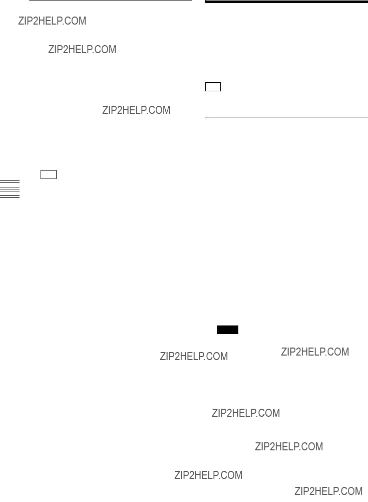
The cropping process when the transition is executed is as follows.
Last 5%
t: Transition execution time
y: Amount of change of transition and crop
Cut: Cropping is maintained during transition execution and then removed at the point in time that the transition ends.
Last 5%: Cropping is maintained as is until the transition progresses to 95% and then removed during the remaining 5%.
Linear: Cropping is linearly removed from the start of the transition in accordance with the progression of the transition.
Adding an Edge to a DME Wipe Pattern
With a DME wipe, you can add a border around the pattern (border) and defocus the edge of an added border (soft border).
The edge color and background color can also be adjusted.
For details on how to add an edge, see ???Adding the Edge to the Wipe Pattern??? (page
Settings menu: [DME Wipe Edge], [DME Wipe Edge Color] (page
Adjusting the Background Color of a
DME Wipe
You can adjust the background color of a DME wipe.
Settings menu: [DME Wipe Bkgd Color] (page
Tips
???The background color of the DME wipe can only be used for Flip Tumble DME wipe patterns.
???The background color of the DME wipe is shared with the edge color of the wipe pattern.

Details on [Effect] Menu
[Effect] Menu
Press the EFF button in the menu control block to display the [Effect] menu.
Switching Video 2 Chapter

Switching Video 2 Chapter
[Wipe Modify] Menu
Display the [Wipe Modify] menu by pressing the V1 knob while [Wipe Adjust] is selected.

Switching Video 2 Chapter

Switching Video 2 Chapter
[DME Wipe Modify] Menu
Display the [DME Wipe Modify] menu by pressing the V1 knob while [DME Wipe Adjust] is selected.
The crop function is not available in the following cases.
???When the 1701 (Mosaic) or 1702 (Defocus) effect pattern is selected
???When the KEY next transition selection button is selected

Setting Keys
A key is a function for cutting out the background image and then inserting an image or text in that portion. The signal for cutting out the background is called a key source, the signal for filling the cutout portion is called a key fill, and the block for processing a key is called a keyer.
This section describes how to make detailed adjustments for keys.
With this unit, you can make the following settings for keys.
???Basic Operations for Keys (page
???Setting Key Transitions (page
???Selecting the Pattern and Direction for Key Wipes (page
???Making Detailed Adjustments to Key Wipe Patterns (page
???Setting Key DME Wipes (page
???Making Detailed Adjustments to Key DME Wipe Patterns (page
???Selecting Key Types (page
???Making Detailed Adjustments to the Luminance Key (page
???Making Detailed Adjustments to the Linear Key (page
???Making Detailed Adjustments to the Chroma Key (page
???Setting the Key Fill and Key Source (page
???Setting a Mask for a Key (page
???Adding an Edge to a Key (page
???Adjusting the Size and Position of the Key (page
For the basic operating procedures of the luminance key and chroma key, see ???Composing Images with Keys??? (c Basic Operation).
Make the key and the key transition settings in the [Key] menu.
For details on the [Key] menu item, see ???Details on [Key] Menu??? (page
Tip
In 3D mode, the [Key] menu is not displayed.
Basic Operations for Keys
Use the following procedure to perform basic operations for keys.
Material selection
r
Transition configuration
r
Key configuration
r
Transition execution
Depending on where you want to perform the key transition, perform one of the following two variations for basic key operations.
???Effect transition (select KEY next transition button)
???Key transition (page
Effect transition
Material selection
Press the KEY bus delegation button.
r
Select the video for program output.
r
Select the key material (i.e., the image to be superimposed on the program video output).
Transition configuration j
Press the KEY next transition selection button to light it.
r
Press the MIX button or EFF button.
r
Set the transition type for the effect transition.1)
r
Select the pattern and direction for the wipe or DME wipe if necessary.1)
1) Use the [Effect] menu.
Select the key type.
r
Make detailed adjustments to the key if necessary.
Switching Video 2 Chapter
Setting Keys

Execute the transition using the fader lever, CUT button, or AUTO TRANS button.
Make detailed adjustments to the key if necessary.
Execute the transition using the KEY TRANS button.
Setting Key Transitions
Set the key transition rate and key transition type for when a key transition is performed.
You can select any of the following transition types. Cut: Quickly insert (cut in) or remove (cut out) the key. Mix: Gradually insert (fade in) or remove (fade out) the
key.
Wipe: Use the wipe to cut out the background and then embed a key.
DME (Digital Multi Effects): Use a DME effect and apply the same effect as the DME wipe to the key (key DME wipe).
Selecting the Pattern and Direction for Key Wipes
You can cut out the background from a wipe pattern selected for a key transition and then embed a key.
Settings menu: [Key Wipe Modify] (page
For details on the wipe directions, see ???Selecting the Pattern and Direction for Wipes??? (page
For details on the wipe pattern numbers, see ???Effect Pattern List??? (c Basic Operation).
Making Detailed Adjustments to Key Wipe Patterns
You can set the position of a wipe pattern, and apply various variations and modifiers in [Key Wipe].
To display the [Key Wipe] menu
Display the [Key] menu, turn the V1 knob to select [Key Wipe], and press this knob.
The setting items in the [Key Wipe Modify] menu are the same as those of [Wipe Modify] in the [Effect] menu. For details on the setting items, see the corresponding sections of ???Making Detailed Adjustments to Wipe Patterns??? (page
Setting Key DME Wipes
For a key, you can make the same settings as with DME wipe.
Settings menu: [Key DME Wipe] (page
For details on the DME wipe directions, see ???Selecting the Pattern and Direction for Wipes??? (page
For details on the wipe pattern numbers, see ???Effect Pattern List??? (c Basic Operation).
Making Detailed Adjustments to Key DME Wipe Patterns
You can adjust the position of a key DME wipe pattern and adjust the size of a
To display the [Key DME Wipe Modify] menu
Display the [Key] menu, turn the V1 knob to select [Key DME Wipe], and press this knob.
The setting items that can be configured in the [Key DME Wipe Modify] menu are the same as those of the [DME Wipe Modify] menu for a DME wipe (except for the crop item). See the corresponding sections of ???Making Detailed Adjustments to DME Wipe Patterns??? (page
Selecting Key Types
Select the key types to cut off the images. You can select any of the following key types.
Lum (luminance key) / Lin (linear key): Use these when inserting titles or logos onto the image.
Use brightness signals such as those for black and white text as the key source.
Tip
Linear keys have a reduced variability in gain that allows more precise adjustment when compared to luminance keys.
Chr (chroma key): Use this when combining images of people with a background image, for example. Create the key source from a particular color within the input image.
Settings menu: [Key Type Select] (page
Making Detailed Adjustments to the Luminance Key
You can make detailed adjustments for the cutout condition of the background, the key density, and other settings for composing video with luminance keys.
Settings menu: [Lum Key Adjust (1/2)] (page
Making Detailed Adjustments to the Linear Key
You can make detailed adjustments for the cutout condition of the background, the key density, and other settings for composing video with linear keys.
Settings menu: [Lin Key Adjust (1/2)] (page
Making Detailed Adjustments to the Chroma Key
When, for example, you want to
For details on automatic chroma key adjustment, see ???Composing Images with Chroma Keys??? (c Basic Operation).
To display the [Manual Chromakey] menu
Display the [Key] menu, turn the V1 knob to select [Chromakey Manual Adj], and press this knob.
For details on the [Manual Chromakey] menu, see ???[Manual Chromakey] Menu??? (page
Setting the Key Fill and Key Source
Select the signal to use for the key fill and the signal selection mode to use for the key source.
Settings menu: [Key Fill/Src Select] (page
Key source selection modes
Self: Selects the signal of the key source bus as the key source.
If the chroma key is selected as the key type, select [Self].
Auto: Automatically selects the signal of the key fill bus and the paired signal assigned to a cross point button as the key source.
Split: Allows you to select the key source bus signal separately from the key fill bus signal.
For details on selection, see ???Selecting the key fill and key source separately??? (c Basic Operation).
Switching Video 2 Chapter
Setting Keys

Switching Video 2 Chapter
The key fill and key source pairs selected when [Auto] is selected are as follows.
Signals other than the above Same signal as key fill
1)If you perform keying with white video as the key source, the key fill video will fill the entire screen.
Key fill selection modes
Bus: Signal selected with a cross point button
Matte: Signal generated with the color matte generator within the unit (you can adjust the color under [Key Fill Mat Adjust])
Setting a Mask for a Key
Key mask is a function for masking a portion of the key signal.
Settings menu: [Key Mask] (page
Adding an Edge to a Key
You can add a border to the edge of the key (border) and defocus the edge of the key (soft).
Note
When you add a border to a key, the positions of the key fill and key source will move downward.
Setting modifiers for the key edge
Turn drop mode on or off and set the type of modifier.
???If you turn drop mode on, the position of the key fill and key source will move downward, regardless of whether borders are added. If you do not want to move the position of the key in response to whether key border is turned on or off, turn drop mode on.
???You can select any of the following modifiers.
NormalBorder
Normal: The state in which a border around the key is not added.
Border: Allows you to add a border around the key and adjust the width and border density.
Settings menu: [Key Edge Type] (page
Adjusting the Size and Position of
the Key
Under the [Resizer] menu, you can apply effects, such as reducing, enlarging, moving, and changing the aspect ratio, to the created key portion in a similar manner as DME (resize function).
Notes
???If a resize effect is applied to the key, there will be a
???Of the DME wipe, key DME wipe, and resize functions, only one can be used at any one time.
To enable the resize function
Display the [Key] menu, turn the V1 knob to select [Resizer], and turn the V4 knob to select [On]. (See page
To display the [Resizer] menu
Display the [Key] menu, turn the V1 knob to select [Resizer], and press this knob.
For details on the [Resizer] menu, see ???[Resizer] Menu??? (page

Details on [Key] Menu
[Key] Menu
Press the KEY button in the menu control block to display the [Key] menu.
Switching Video 2 Chapter

Switching Video 2 Chapter

Switching Video 2 Chapter

Switching Video 2 Chapter

Switching Video 2 Chapter
[Auto Chromakey] Menu
Display the [Auto Chromakey] menu by pressing the V1 knob while [Chromakey Auto Adj] (page

Switching Video 2 Chapter

[Key Wipe Modify] Menu
Display the [Key Wipe Modify] menu by pressing the V1 knob while [Key Wipe] (page
Switching Video 2 Chapter

Switching Video 2 Chapter
[Key DME Wipe Modify] Menu
Display the [Key DME Wipe Modify] menu by pressing the V1 knob while [Key DME Wipe] (page
Overview
You can adjust the audio input in detail, set the audio levels, and specify the connectors to use for audio output for each audio channel.
Adjust and set the audio from the [Audio Channel] menu for each audio channel.
To display the [Audio Channel] menu
Press the ACCESS/PFL button in the same column as the channel fader assigned to the audio channel you want to adjust.
ACCESS/PFL buttons
For details on assigning an input signal to each channel fader, see ???Assigning Audio Input Signals to the Channel Faders??? (c Basic Operation).
Mixing Audio 3 Chapter
Details on [Audio Channel] Menu

Mixing Audio 3 Chapter

Mixing Audio 3 Chapter

Memory Frame and Freezing Image Input 4 Chapter
Input freeze is a function that allows you to freeze images from individual input signals.
Frame memory is a function that allows you to freeze images and then write it to the memory of the unit so that you can use it as input material.
Images that are stored in frame memory can be used as the video input signals (FM) of the cross point buttons (PGM buttons and PST/KEY buttons).
Tip
Input freeze and frame memory are not available in 3D mode (the [Frame Memory] menu is not displayed).
1 Press the FM button in the menu control block to display the [Frame Memory] menu, and turn the V1 knob to select [Input Freeze].
2 Turn the V3 knob to select the input signal, turn the V4 knob to select [On], and press the V4 knob at the timing you want to freeze.
The input image is frozen.
Tip
If you want to freeze an image again, select [Off], press the V4 knob, and then select [On] again.

Selecting Frame Memory for Use as Frame Memory Video (FM)
Display the [Frame Memory] menu, turn the V1 knob to select [Select], and turn the V4 knob to select the frame memory to which the image you want to use as the frame memory video is saved.
Frame Memory 1 to 12 are indicated as ???FM1,??? ???FM2,??? ...
???FM12.???
Saving Images to Frame Memory
Select the frame memory to which to save (Frame Memory 1 to 12), select the input signal to be used as the source, and then freeze the input image to write it to memory.
1 Display the [Frame Memory] menu, turn the V1 knob to select [Frame Memory Freeze], and then press the knob.
The [Frame Memory Freeze] menu appears.
2 Turn the V1 knob to select the frame memory to which to save the image ([Frame Memory 1] to [Frame Memory 12]), turn V2 and V3 knobs to select the source images, turn the V4 knob to select [On], and press the V4 knob.
The input image is saved to memory.
Tips
???If the [Store] parameter is set to [Off], the input video of the frame memory is output.
???If [Src K] is set to [Black], an all white signal is assigned to the key source image.
3 Press the FM menu selection button to exit the [Frame Memory Freeze] menu.
Note
The frame memory ([Frame Memory 1] to [Frame Memory 12]) selected with the V1 knob in the [Frame Memory Freeze] menu will be automatically selected to the FM of the video input signal, and this will be reflected in the selection status of [Select] in the [Frame Memory] menu.
Memory Frame and Freezing Image Input 4 Chapter

Memory Frame and Freezing Image Input 4 Chapter
Importing and Exporting
Images
You can use a USB flash drive to import images to the unit as frame memory, and export the frame memory saved in the unit.
Importing Images
File formats supported for import
???TGA
???TIFF
???BMP
Notes
???Enter up to 25
???If an image is too large, the protruding portions will be cut. If an image is too small, the missing portions will be filled with black.
???Import operations are not guaranteed for TGA and TIFF files that include layer information.
1 Copy the images you want to import to the following folder on a USB flash drive, and then insert the USB flash drive into the USB connector of the unit.
Folder name: \Sony\MCS\FM
2 Display the [Frame Memory] menu, turn the V1 knob to select [Import], and press this knob.
The data in the USB flash drive is read and the files that can be imported are displayed.
3 Turn the V1 knob to select the first file to import, turn each knob to specify the frame memory and the number of files to import, and press the V4 knob to start importing.
When the V4 knob is pressed, the specified number of files are imported.
Tips
???If you import TGA files or TIFF files that include alpha channels, a frame memory that includes a key source will be created.
???You can import
???Compressed TIFF files cannot be imported.
???If you import BMP files, or TGA or TIFF files that do not include alpha channels, a frame memory with an
???If a frame memory is registered to the specified frame memory number, it will be overwritten by the imported image.
Export Frame Memory
You can export the frame memory stored in the unit to a USB flash drive.
1 Insert the USB flash drive into the USB connector of the unit.
2 Display the [Frame Memory] menu and turn the V1 knob to select [Export].
3 Turn each knob to select the frame memory to export, and then press the V4 knob to start exporting.
When the V4 knob is pressed, the specified number of frame memory is exported.
???Only BMP format files can be exported. Alpha channels cannot be added.
???The folder to which the files are exported and the file names are as shown below.
Folder name: \Sony\MCS\FM
File name:
(# is the frame memory number [01 to 12])

Importing and Exporting
Configuration Data
You can export configuration data in which various settings of the unit have been saved to a USB flash drive, and import saved configuration data to the unit.
Tip
Configuration data contains various settings of the unit. When you want to, for example, restore previous settings, you can easily make the settings by importing the configuration data. We recommend that you save the configuration data such as when you change the settings.
Exporting Configuration Data
1 Insert the USB flash drive into the USB connector of the unit.
2 Press the FILE button in the menu control block to display the [File] menu, turn the V1 knob to select [Export Config], and press the V4 knob to start exporting.
Tip
The folder to which the files are exported is as shown below.
Folder name:
Note
The following settings are not saved under configuration data.
Front panel buttons
???ACCESS/PFL (1 to 6)
???DIM
???MONITOR SEL
???CH ON (1 to 6)
???Bus delegation buttons (BKGD, KEY, AUX 1, AUX 2)
???Menu selection buttons
???Numeric keypad buttons (EFF, SNAPSHOT, DIRECT/ ESC)
Menus
Miscellaneous
??? Frame memory video
Files Exporting and Importing 5 Chapter
Files Exporting and Importing 5 Chapter
Importing Configuration Data
1 Insert the USB flash drive that stores the configuration data you want to restore into the USB connector of the unit.
2 Display the [File] menu, turn the V1 knob to select [Import Config], and press this knob.
The data in the USB flash drive is read and the configuration data that can be imported is displayed.
3 Turn the V1 knob to select the configuration data to import, and press the V4 knob to start importing.
When importing is complete, a message prompting you to restart the unit appears.
4 Press the V3 knob (OK), and then turn off the unit and turn it on again.
Tip
When you import configuration data, the startup mode will automatically change to [User].
For details on the startup mode, see ???Startup Mode??? (page
Importing and Exporting
Snapshots
You can export the snapshots stored in the unit to a USB flash drive, and import the snapshots stored in the USB flash drive to the unit.
Tip
Snapshots cannot be imported or exported in 3D mode.
Exporting Snapshots
1 Insert the USB flash drive into the USB connector of the unit.
2 Display the [File] menu and turn the V1 knob to select [Export Snapshot], turn each knob to specify the files to export, and press the V4 knob to start exporting.
When the V4 knob is pressed, the specified number of snapshots are exported.
The folder to which the files are exported and the file names are as shown below.
Folder name: \Sony\MCS\SNAPSHOT
File name:
Note
When exporting snapshots, make sure that the number of files in the folder does not exceed 99.

Importing Snapshots
1 Insert the USB flash drive that stores the snapshots you want to import into the USB connector of the unit.
2 Display the [File] menu, turn the V1 knob to select [Import Snapshot], and then press the knob.
The data in the USB flash drive is read and the snapshots that can be imported are displayed.
Tip
Snapshot files are displayed in order, starting with the oldest.
3 Turn the V1 knob to select the snapshot to import, turn each knob to specify the snapshots to import, and press the V4 knob to start importing.
When the V4 knob is pressed, the specified number of snapshots are imported.
If a snapshot is already stored to the specified snapshot number, it will be overwritten by the imported snapshot.
Formatting a USB Flash
Drive
1 Insert the USB flash drive into the USB connector of the unit.
2 Display the [File] menu, turn the V1 knob to select [USB Memory Format], and press the V4 knob to start formatting.
Tip
The following folders are created when formatting is performed.
Folder name:\Sony\MCS\CONFIG \Sony\MCS\FM \Sony\MCS\SNAPSHOT
Files Exporting and Importing 5 Chapter
Formatting a USB Flash Drive

3D System
Chapter6
???The connectors that can be used for 3D video input and the cross point buttons to which video signals can be assigned are fixed as shown below.
???The connectors to which 3D video output signals can be assigned are fixed as shown below.
???Use a reference signal to synchronize the images from the 3D video input device and this unit.
???The TALLY/GPI connector will be dedicated to TALLY. The TALLY will be fixed at IN1 (SDI IN 1, IN 2) and IN2 (SDI IN 3, IN 4).
Making the Necessary
Settings
Make the settings for operating the unit in a 3D system in the [Setup] menu.
Display the [Setup] menu by pressing the SETUP button in the menu control block.
Setting the Signal Format and Video
Size
1 Display the [Setup] menu, select [System] menu > [System Format], and use the corresponding knobs to make each of the following settings.
Tip
The [Aspect] of the video is fixed at 16:9.
For details on the setting, see ???Configuring the Signal Format and Aspect Ratio??? (c Basic Operation).
2 Press the V3 or V4 knob.
A message prompting you to restart the unit appears.
3 Press the V3 knob (OK).
Turning 3D Mode On
1 Display the [Setup] menu, select [System] menu > [3D Mode], turn the V4 knob to select [On].
2 Press the V4 knob.
A message prompting you to restart the unit appears.
3 Press the V3 knob (OK), and then turn off the unit and turn it on again.
Tips
???In 3D mode, the BKGD bus delegation button will be lit, and the KEY, AUX 1, and AUX 2 buttons will be disabled.
???Next transition is fixed at BKGD.
???Transition types will be fixed at MIX.
???The FTB and KEY TRANS buttons in the transition control block will be disabled.
???The numeric keypad block will be disabled.
???In the menu control block, only the MISC, FILE, and SETUP buttons will be enabled.
In addition, menus will be restricted as follows.
[Misc] menu
[Setup] menu
System 3D 6 Chapter

[File] menu
???The following data will not be saved by the [Startup Define] operation in the [Setup] menu. These settings will return to default values at each startup.
???PGM bus
???PST bus
???Effect transition rate: 30
Confirming 3D Video Output
3D video input is assigned to the cross point buttons (PGM buttons and PST/KEY buttons) 1 and 2.
Press cross point buttons 1 and 2 and confirm that 3D video is output.
System 3D 6 Chapter

Enabling/Disabling Operation from External Devices
Enable or disable the GPI port which is used for operation from external devices.
1 Display the [Misc] menu, turn the V1 knob to select [Port Enable], and use the V3 knob to make the setting.
Connecting with External Devices
Set up a connection with an external device in [GPI/Tally] of the [Setup] menu.
Tip
In 3D mode, [GPI/Tally] is not displayed.
For details on the [GPI/Tally] menu items, see ???Details on [GPI/Tally] Menu??? (page
For details on the pin assignment of the TALLY/GPI connector, see ???TALLY/ GPI connector??? (c Basic Operation).
Setting GPI Inputs
Set the operation and trigger type of the GPI input contacts.
Settings menu: [Setup] menu > [GPI/Tally] menu > [GPI Input 1] to [GPI Input 4] (page
You can select from the following operations. NotUse: No operation
CT: Cut
AT: Auto Transition
KeyCT: Key Cut
KeyAT: Key Auto Transition
Aux1CT: Aux1 Cut
Aux1AT: Aux1 Auto Transition
Aux2CT: Aux2 Cut
Aux2AT: Aux2 Auto Transition
SS1 to SS20: Snapshot Recall (1 to 20)
You can select from the following trigger types. NotUse: The input pulse is ignored.
Rise: The trigger is applied at the rising edge of the input pulse.
Fall: The trigger is applied at the falling edge of the input pulse.
Any: The trigger is applied when the input pulse is inverted.
Setting GPI Outputs/Tallies
Set the GPI outputs or tallies.
Settings menu: [Setup] menu > [GPI/Tally] menu > [GPI Output/Tally 1] to [GPI Output/Tally 8] (page
You can select from the following trigger types. NotUse: The output is fixed at a high level.
Rise: The trigger causes the output to decrease to a low level, and that status will continue for a certain duration (1 to 2 frames).
Devices External Controlling 7 Chapter

Fall: The trigger causes the output to decrease to a high level, and that status will continue for a certain duration (1 to 2 frames).
Any: Every time the trigger is activated, the output???s high and low levels change alternately.
If the GPI outputs are used as tallies, the relationship between Tally 1 to 8 and the input signals is as follows.
Devices External Controlling 7 Chapter
Details on [GPI/Tally] Menu
To display the [GPI/Tally] menu, display the [Setup] menu and press the V1 knob while [GPI/Tally] is selected.

Devices External Controlling 7 Chapter

Devices External Controlling 7 Chapter

Overview
Set up the overall system in the [Setup] menu.
The [Setup] menu contains the following items.
To display the [Setup] menu
Press the SETUP button in the menu control block.
To select a menu item
Display the [Setup] menu and then turn the V1 knob to select a menu item.
System Setup (System)
Make system related settings in the items of the [Setup] menu > [System] menu.
Supported input reference signals
You can use any of the following signals as the input reference signal for the unit.
Menu) ([Setup] Setup 8 Chapter

Menu) ([Setup] Setup 8 Chapter
Details on [System] Menu

Audio Setup (Audio)
Assign audio signal inputs to channel faders and make audio related settings in the items of the [Setup] menu > [Audio] menu.
SDI output embedded audio and audio signal combinations
The following table shows the possible combinations for output.
Tip
PGM and MIX are handled as a pair.
???When PGM/MIX is assigned to either L or R, the same assignment is made to the other automatically. For example, if L is assigned to
???If one of L and R is then assigned to other than PGM/MIX, the other is automatically set to ???None.???
Details on [Audio] Menu
Menu) ([Setup] Setup 8 Chapter

Menu) ([Setup] Setup 8 Chapter
Video Input Setup (Video (Input))
Make video input related settings in the items of the [Setup] menu > [Video (Input)] menu.
About DVI input signals
???Set the resolution of the DVI signal to be input to one of the following in accordance with the setting of the signal format of the unit (page
Tip
Although signals with resolutions other than 1920 ?? 1080 may be accepted when DVI input signals are set to digital, operation is not guaranteed.
???The image size of the DVI input signals will be adjusted to fit the screen of the unit???s signal format while maintaining its aspect ratio.
Details on [Video (Input)] Menu
Menu) ([Setup] Setup 8 Chapter

Assigning Video Input Signals to the Cross Point Buttons (Video (XPT))
Assign video signals to the cross point buttons (PGM buttons and PST/KEY buttons) in the items of the [Setup] menu > [Video (XPT)] menu.
For details on the setting procedure, see ???Assigning Video Signals to the
Tip
In 3D mode, this menu is not displayed.
Using the Shift Button Function
By using the cross point button 8/SHIFT as the Shift button, you can assign a total of 14 materials (seven to cross buttons 1 to 7, and seven to cross buttons 1 to 7 + Shift button (cross point button 8/SHIFT)).
Settings menu: [XPT Shift Mode] (page
Numbers are assigned to the cross buttons as shown below in accordance with whether or not the Shift button function is on or off.
Shift button function: Off
Shift button function: On (shift mode)
The following table shows the factory default settings for assignments.
Menu) ([Setup] Setup 8 Chapter
Details on [Video (XPT)] Menu

Video Output Setup (Video (Output))
Set the video output signal to assign to each video output connector in the items of the [Setup] menu > [Video (Output)] menu.
Tip
In 3D mode, this menu is not displayed.
Details on [Video (Output)] Menu
Menu) ([Setup] Setup 8 Chapter

Setup of Other Video Related Items (Video (Misc))
Make other settings related to videos in the items of the [Setup] menu > [Video (Misc)] menu.
Details on [Video (Misc)] Menu
1 Copy the software to be installed to the USB flash
Displaying Various drive and then insert the USB flash drive into the USB connector of the unit.
Information (Information)
Tip
Menu) ([Setup] Setup 8 Chapter
You can confirm various information on the application software and the firmware in the items of [Setup] menu > [Information].
Installing Application Software and Firmware (Install)
Install application software and firmware onto the unit from [Setup] menu > [Install].
Tip
It is not possible to individually select which software to install. All of the application software and firmware are installed together at one time.
Copy the software to be installed to the following folder.
Folder name: \Sony\MCS\INSTALL
2 Display the [Setup] menu > [Install] menu and then press the V4 knob to start the installation.
When installation is complete, a message prompting you to restart the unit appears. Confirm that no errors have occurred (i.e., ???E??? is not displayed).
Tip
For details on the message that appears at installation completion, see ???Message List??? (page
3 Press the V3 knob (OK), and then turn off the unit and turn it on again.
4 Check the version information of the application software and firmware under [Information] in the [Setup] menu.
Appendix
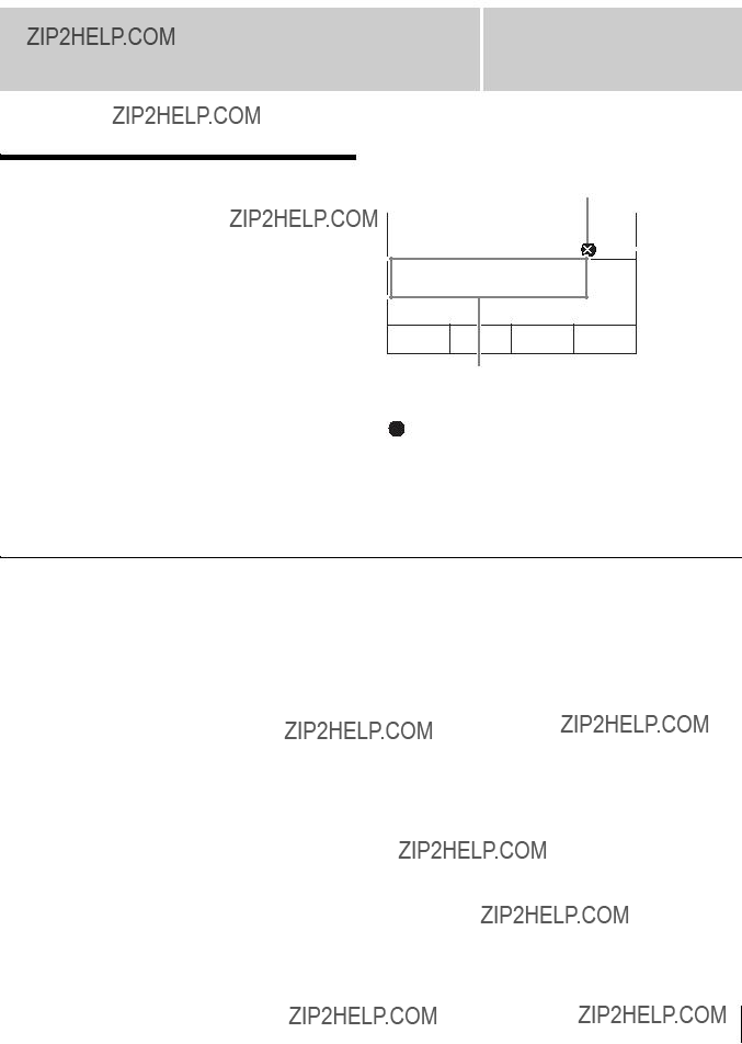
Message List
When a problem occurs on the unit during operation, the following types of messages appear. Before contacting your local Sony representative, view the following lists and check the possible solutions. If the problem persists, write down the message number that appears and contact your local Sony representative.
Message example:
Message type
USB memory is not recognized.
Confirm the USB memory.
Select
 Enter
Enter
Message
The following message types exist.
 (Error): Indicates an inability to continue operation, malfunction, or other severe error.
 (Warning): Indicates that problems may occur if you continue operation.
 (Information): Indicates a notification.
Errors
Message List

Warnings

Information
Appendix
Message List

Index
Index
Numerics
8/SHIFT
A
ACCESS/PFL Button
Incremental Adjustment
Aspect Ratio
Audio
Audio Channel Menu
Input Trim
PGM Assign
Audio Level Meters
Audio Output Delay
SDI OUT MULTI VIEWER Assign
SDI OUT PGM Assign
Audio Monitor
Auto Adjust Execute
Auto Adjust Execute
AUTO TRANS Button
B
BKGD Button
Bus Delegation Button
AUX 1 and 2 Buttons
BKGD Button
KEY Button
C
D

M
Menu
Operations
Viewing
Menu Control Block
Menu Selection Button
EFF Button
FILE Button
FM Button
KEY Button
MENU1 and 2 Buttons
MISC Button
SETUP Button
MENU1 and 2 Buttons
MIC/LINE Level
MISC Button
Mix
MIX Button
MONITOR LEVEL Adjustment
Knob
MONITOR SEL Button
Mosaic
Multi Viewer
N
NAM
Next Transition Selection Button
BKGD Button
Index
Index

Index
O
P
Peak Indicator
PFL
PGM
Pin Configurations
PinP
Positioner
Preview Video
Program Fader
Program Video
PST/KEY
R
Reference Signal Input/Output
Block
S
Sample Mark
Sample Mark Adjust
Saving Settings
SDI OUT AUX Assign
SDI OUT PGM Assign
SETUP Button
Multi Viewer
Startup Define
Signal Assign
Signal Format
Slide
Snapshot
Recalling
Saving
SNAPSHOT Button
Specifications
Squeeze
Startup Define
STORE Button
System Configuration Example
HD System
System Format
T
Tally Input
Time
Transition Control Block
Transition Indicator
Transition Rate
Transition Rate Area
Transition Type Selection Button
EFF Button
MIX Button
Troubleshooting
The material contained in this manual consists of information that is the property of Sony Corporation and is intended solely for use by the purchasers of the equipment described in this manual.
Sony Corporation expressly prohibits the duplication of any portion of this manual or the use thereof for any purpose other than the operation or maintenance of the equipment described in this manual without the express written permission of Sony Corporation.
Trademarks
HDMI, the HDMI logo, and
Other products or system names appearing in this document are trademarks or registered trademarks of their respective owners.
Further, the ?? or ??? symbols are not used in the text.

Sony Corporation