C9000 Series
Color LED Page Printer
Service Manual
ODA
C9000 Series
Color LED Page Printer
Service Manual
ODA
Document Revision History

PREFACE
This maintenance manual provides procedures and techniques for the troubleshooting, maintenance, and repair of C9000.
This manual is written for maintenance personnel, but it should always be accompanied with the C9000 User???s Manual for procedures for handling and operating C9000. For repairing each component of C9000, see the Troubleshooting manual.
[Notices]
The contents of this manual are subject to change without prior notice.
Although reasonable efforts have been taken in the preparation of this manual to assure its accuracy, this manual may still contain some errors and omissions. OKI will not be liable for any damage caused or alleged to be caused, by the customer or any other person using this maintenance manual to repair, modify, or alter C9000 in any manner.
[Warning]
Many parts of C9000 are very sensitive and can be easily damaged by improper servicing. We strongly suggest that C9000 be serviced by OKI???s authorized technical service engineers.

2.7Transfer Control Responds to Environmental Changes
3.3.4Control panel Assy/ Control panel bezel/ LED control PWB/ Toner sensor/

1.SPECIFICATIONS
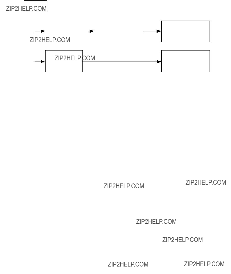
1.1Basic System Configuration
The basic system configuration of C9000 is illustrated in Figure 1.1.
LED Head

Figure 1.1

1.2Printer Engine Specifications
The inside of the printer is composed of the followings:
???Electrophotographic Processor
???Paper Paths
???Controller Block (CU and PU)
???Operator Panel
???Power Units
Figure
Figure 1.2
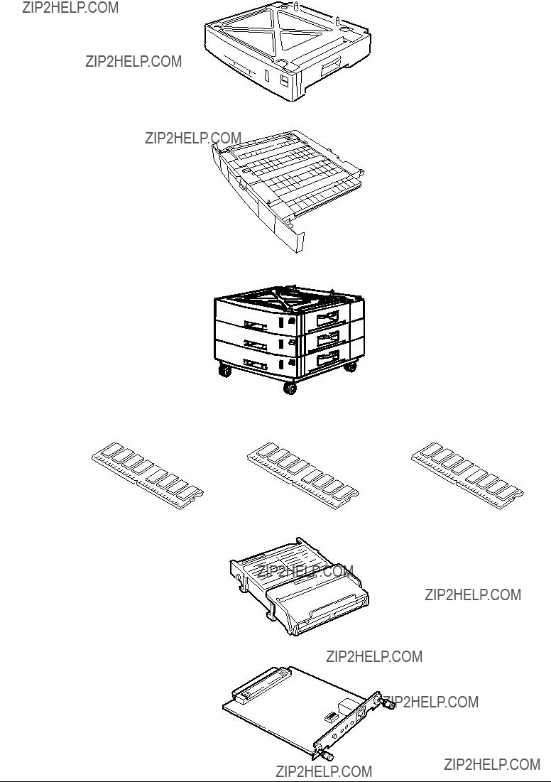
1.3Option Configuration
The followings are available as options on C9000.
(1)2nd Tray/ 3rd Tray
(2)Duplex Unit
(3)
(4)Expansion Memory 64/128/256MB
(5) Internal Hard Disk
(6)Ethernet Board

1.4Specifications
(4)Print Speed Color: 21 pages per minute (Transparency: 5 pages per minute)
Monochrome: 26 pages per minute (Transparency: 15 pages per minute)
Postal Card, Label, Thick Paper: 10 pages per minute
(5) Resolution 600 ??? 600 DPI / 600 x 1200 DPI (C9200 series) & 1200 x 1200 DPI (C9400 series)
(6)Power Input 100VAC ?? 10%

(12) Temperatures and Relative Humidities
Temperature
Humidity
(13 Printer Life 1,000,000 pages (on a A4 basis) or five years
2.OPERATION DESCRIPTION
C9000, a tandem color electrophotographic page printer, adopts technologies such as
Figure
Fan 0 (power eject)
Edge Side
Removed-
DUP
DUP Front Clutch DUP Rear Clutch
Figure 2.1

2.1Main Control Board
Figure
2.0V Regulator
Figure 2.2

(1)CPU
The CPU is
(2)Secondary Cache SRAM
SRAM is included as a secondary cache of the CPU on the board.
(3)ROM
The ROM is inserted into the three
(4)RAM
The RAM is inserted into the four
SDRAM DIMM Specifications:
Configuration: Without parity and ECC. Requires the SPD information. Number of chips contained = 8 or 16.
(5)EEPROM
The EEPROM (16Kb), an
(6)Flash ROM
A
(7)Memory Control LSI (CI)
A
(8)Interface Control LSI (C2)
A BGA package ASIC made by Toshiba, which controls the PU command I/F, operator panel I/F, IDE I/F, Centronics I/F, USB I/F, PCI I/F, EEPROM and SPD (SDRAM DIMM) I/F.
(9)IDE HDD
An IDE connector is
(10)PCI Bus Option
Two PCI I/F slots are provided for option board use. The bus, which uses an Oki Data original connector, can accept an Ethernet board.
(11)Host Interface
Standard: Centronics
Additional Board: (connected to PCI BUS) Ethernet Board
2.2Engine Control Board (K73 PWB)

 Fan control
 Cover front/upper open
 Stacker full
 Test switch
 (Power supply cooling)
Paper Feed System Sensors 
(Paper Feed, Paper Registration and Eject Sensors)
MT Sensor (Stage position and paper empty)
Cassette 1 Sensor (Paper empty and near empty)
Shutter, clutch, belt and fuser checks
Cassette size
Figure 2.3
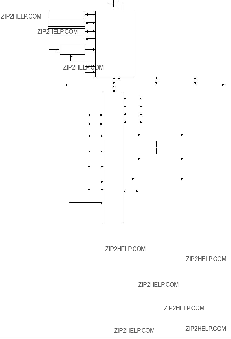
The engine control block (PU) is controlled by the engine control board (K73 PWB) which consists of a CPU (MSM66Q577), general LSI chip, flash ROM, EEPROM, pulse motor drivers, and video memory (see Figure 2.3).
(1)CPU
This, a
(2)General LSI
This LSI

(3)Flash ROM
8 megabits of flash ROM
(4)EEPROM
4 kilobits of EEPROM
(5)Pulse Motor Driver
The pulse motor driver (A2918, A2919, A3955) drives nine pulse motors to revolve the EP and carry media.
(6)SRAM
This SRAM
2.3Power Units
There is a
(1)
This circuit generates the following voltages:
(2)
This circuit generates the following 34V or more voltages, which are required for electropho- tographic process, according to control sequences from the control board.

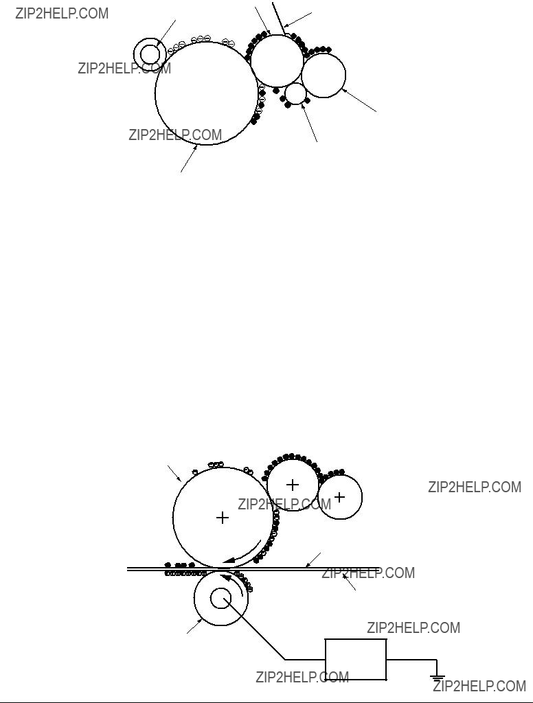
2.4Mechanical Processes
Figure 2.4 shows the mechanical processes of the printer.
x 4 K Y M C
Figure 2.4

2.4.1Electrophotographic process
(1)Electrophotographic process
The following is the outline of electrophotographic process:
1Charging
DC voltage is applied to the charging roller and the surface of the OPC drum is negatively and evenly charged.
2Exposure
The LED head, under image signals, emits light to the negatively charged surface of the OPC drum. The radiated portions of the drum surface attenuate in negative charge according to the intensity of the light and, based on the surface potentials, a latent electrostatic image is formed on the drum surface.
3Development
Negatively charged toner contacts the OPC drum and, by electrostatic force, adheres to the latent electrostatic image to form a clear image on the drum surface.
4Transfer
Paper is placed on the surface of the OPC drum, and positively, or opposite to the polarity of the toner, charged by the transfer roller on its back to transfer the toner image to the paper.
5Cleaning
The cleaning blade removes residual toner from the OPC drum after the transfer.
6Fusing
The toner image on the paper is fused into place through the application of heat and pressure to it.

(2)Charging
Negative DC voltage is applied to the charging roller contacting the surface of the OPC drum.
Power
Unit
Charging roller
OPC drum
(3)Exposure
The negatively charged surface of the OPC drum is radiated with light from the LED head. The negative charge of the radiated portions of the drum surface attenuates in response to the intensity of the light and a latent electrostatic image responsive to the potentials of the surface is formed on the drum surface.
LED head
LED head
(4)Developing
By the adhesion of toner to the latent electrostatic image on the drum surface, the image is changed to a toner image. The developing is processed at the contact part between the OPC drum and the developing roller.
1 The sponge roller causes toner to adhere to the developing roller. The toner becomes negatively charged.
Sponge roller
Developing roller
OPC drum
2The developing blade removes excess toner from the developing roller and a thin layer of remaining toner is formed on the developing roller.
3The toner is drawn by the latent electrostatic image at the contact portion between the OPC drum and the developing roller.
The latent electrostatic image on the drum surface is made visible with the toner.
(5)Transferring
The transfer roller, which is made of conductive sponge, presses paper against the surface of the OPC drum and brings the paper into intimate contact with the drum surface.
The paper is placed on the drum surface and positively (opposite to the charge of the toner) charged by the transfer roller on its back.
Applying positive high voltage from the power supply to the transfer roller moves the positive charge induced by the transfer roller to the paper surface at the contact portion between the transfer roller and the paper, the paper surface drawing the negatively charged toner from the drum surface.
OPC drum
Paper
Carrier belt
Transfer roller
Power unit
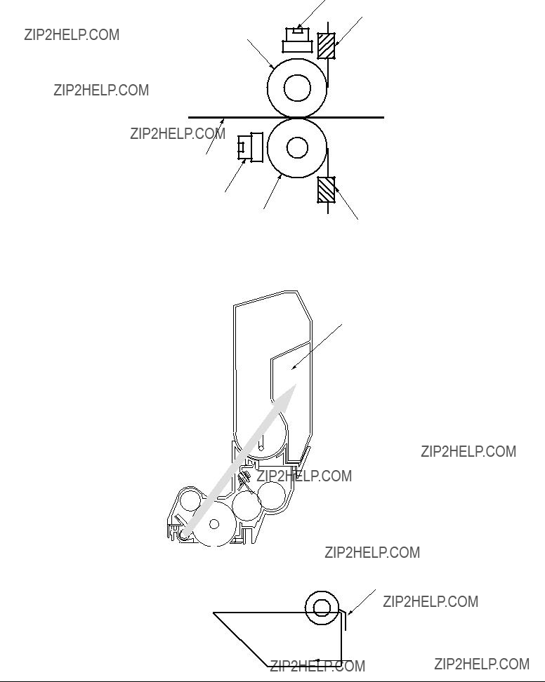
(6)Fusing
When passed between the heat roller and the backup roller, the toner image transferred to the paper is fused into place by the application of heat and pressure to it.
The Teflon coated heat roller is heated by the
Thermostat
Thermistor
Heat roller
Paper
Thermostat
Backup roller
Thermistor
(7)Cleaning
Waste toner area
(8) Cleaning
Residual toner on the transfer belt is scraped with the cleaning blade and collected in the waste toner box of the transfer belt unit.
Waste toner box
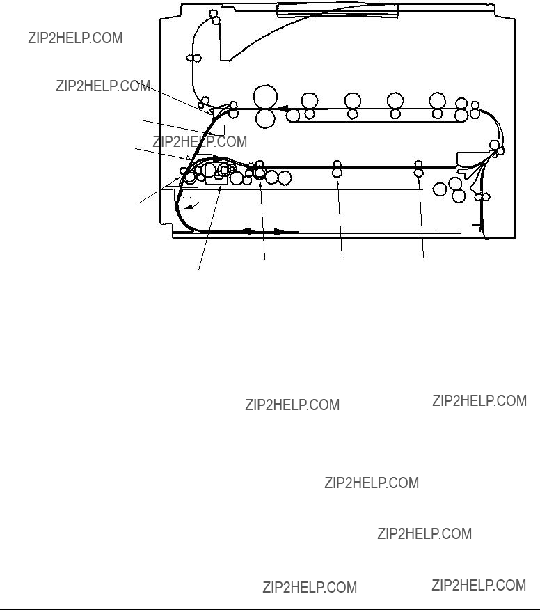
2.4.2Paper running process
Figure 2.5 shows how paper moves in the C9000.
Fuser
Eject roller
Backup roller
Cassette 1
Cassette 2
Cassette 3
Cassette 4
Cassette 5


 Multipurpose tray


 Registration roller Assy (A)
Cleaning blade
Transfer roller


 Feed roller
Figure 2.5 Paper Route

(1)Paper Loading from 1st Tray
1.The paper loading motor runs (CCW), the paper loading clutch is engaged and, until the entrance cassette sensor is turned on, paper is advanced (the on/off operations of the paper loading clutch control the pickup roller).
2.After the paper turns the entrance cassette sensor on, the paper is forwarded a further fixed length and touches the registration roller Assy (A) (this corrects paper skew).
3.The electromagnetic clutch is engaged and the paper is carried onto the carrier belt.
Entrance sensor
Entrance belt sensor
Electromagnetic clutch
Entrance cassette sensor
Registration roller Assy (A)
Feed roller
Electromagnetic clutch
Pickup roller
Loading sensor
Paper
Retard roller
Loading motor 


Figure 2.6

(2)Paper Loading from Option Tray
1.The paper loading motor runs (CW), the paper loading clutch is engaged and, until the carrier sensor on a tray which sits atop a loading tray is turned on, paper is advanced.
2.After the paper turns the carrier sensor on, the paper is forwarded a further fixed length and touches the carrier roller (this corrects paper skew).
3.The carrier clutch is thrown in and the paper is fed into the main body.
Pinch roller
Carrier roller
Carrier clutch 
Carrier sensor
Retard roller
Paper loading motor 
Figure 2.7

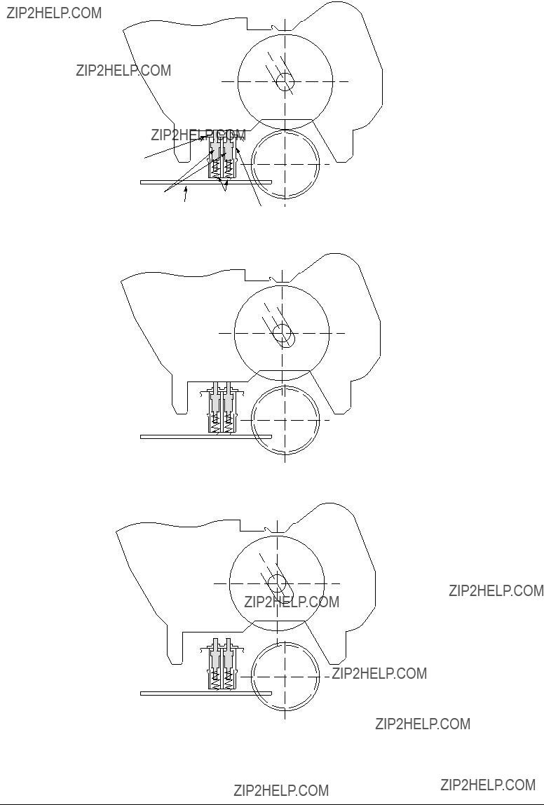
(3)Paper Loading from Multipurpose Tray (MT)
1.The release lever usually pushes down the hopping plate to a position to turn the micro SW on (Figure
2.The running of the motor in the (a) direction drives the MT feed roller, causing the cam to turn. The cam pushes the release lever and the hopping plate picks up paper sent out by the MT feed roller (Figure
3.After the front edge of the paper turns the entrance sensor on, the paper is forwarded a fixed length. The paper stops when its front edge reaches the registration roller Assy (B).
4.Concurrently, the cam pushes down the hopping plate. The release lever that has been placed in its original position by the spring locks the hopping plate (Figure
5.After the completion of the paper feed operation, the registration motor runs in the direction of the arrow (b) to drive the registration roller Assy (B), where the
Oneway clutch gear (2)
MT feed roller
Entrance sensor
Paper
Entrance belt sensor
b a 
Registration roller Assy(B)
Oneway clutch gear (1)
Registration motor
Figure 2.8
Spring
Relerse lever

(4)Carrier Belt
1.The running of the carrier belt motor in the direction of the arrow (a) drives the carrier belt. The belt unit sits with one carrier roller immediately below each color???s drum, and the carrier belt between them. By the application of a fixed voltage, the carrier belt and carrier roller feed paper on the carrier belt into the fuser unit, transferring a toner image from each color???s drum.
Drum
 Carrier belt
KYMC
Carrier (transfer) roller
Carrier (transfer) belt motor
Figure 2.9

(5)Driving and
1.The I/D unit driving and
The drum gear engages with the driving gear and starts revolving to transfer an image on the drum to running paper, where the
2.With the running of the main motor in the direction of the arrow (b), the lever 1 pushes up the I/D unit via the lever 2. After the
The drum gear is not engaged with the driving gear and does not revolve.
3.When the two pins of the
The installation of the I/D unit can also be verified by recognizing the off state of the up-
I/D unit
Drum
Lever 2
Plate
Figure
Figure

(6)Fuser Unit and Paper Ejection
1.A
In response to the running of the heat motor in the direction of the arrow (a), the heat roller turns. This roller fuses a toner image to paper by heat and pressure.
2.At the same time, the four eject rollers move to eject the paper.
3.The paper separator solenoid switches the path back and forth between the route to the
Eject rollers
Fuser unit
 a
a
Fuser motor
Figure 2.11
(7)Duplex Unit
1.When the duplex unit receives an instruction from the printer to print on both sides of a sheet of paper, the solenoid opens the separator after the completion of one side printing of a sheet of paper sent from the tray. The path is switched to that to the duplex unit.
At this time, as the roller (1) turns in the direction of the arrow ???a,???the paper is retracted on the rear of the cassette.
2.When fixed time has elapsed after the front edge of the paper passes through the duplex- in sensor, the rollers reverse and the roller (1) turns in the direction of the arrow ???b???to feed the paper into the duplex unit. After that, the paper passes through the rollers (2), (3) and (4), and ejected with the other side printed, and fed again into the printer.
Separator
Solenoid
 a
a
Motor
Figure 2.12

2.5Sensor
2.5.1Paper related sensors
Driving roller
Belt cleaning blade Registration roller B
Pinch roller 1 Registration roller A
Duplex front sensor
Entrance MT sensor
1st feed roller
Entrance cassette sensor
Auxiliary roller
Duplex rear sensor
Duplex feed roller
Duplex roller
2nd feed roller
Carrier sensor
2.5.2Other sensors
1 Paper Empty sensor
This sensor checks whether the paper cassette is empty.
2Paper Near sensor
This sensor checks whether the paper cassette is near empty.
3MPF Paper Empty sensor
This sensor checks whether the front feeder has paper.
4MPF Hopping switch
This microswitch checks whether the front feeder table is in the up position or in the down position.
5Stacker Full sensor
This sensor checks whether the stacker is full.
6Paper Size switch
This sensor detects the size of paper in the paper cassette.
7EP Up/Down sensor (one for each of colors, Y, M, C and K)
This sensor checks whether the I/D unit is in the up position or in the down position.
8Toner K, Y, M and C sensors
By measuring the time interval between regular opening movements of each sensor???s lever, the sensor checks whether its toner cartridge is empty.
9Temperature sensor
See Section 2.6 (Transfer Control Responds to Environmental Changes)
0Humidity sensor
See Section 2.6 (Transfer Control Responds to Environmental Changes)
AOHP sensor
This sensor detects the presence or the absence of transparencies.
BAlignment sensor
When color misalignment has been corrected, this sensor reads the alignment pattern printed at the right and left ends of the transfer belt (see Section 2.13).

2.6Color Misalignment Correction
C9000 is equipped with multiple LED heads, which can result in color misalignment. The mechanically induced color misalignment is automatically corrected as follows:
(1)Color alignment to be corrected
1 Color misalignment in
3 Color misalignment in
(2)Correcting
Printing the preset color misalignment detection pattern on the belt and, by a reflection sensor, reading the printed pattern detects each color???s misalignment value to determine its correction value. The correction value is used to change each color???s (Cyan, Magenta and Yellow) writing timing in comparison with that of Black.
2.7Transfer Control Responds to Environmental Changes (Room Temperatures and Relative Humidities)
C9000 measures room temperature and relative humidity using a room temperature sensor and humidity sensor, and calculates an optimum transfer voltage under its measurement environment to perform

2.8Paper Jam Detection
C9000 detects paper jams after
Paper Ejection
Paper eject sensor
Duplex Entry
Duplex rear sensor
Duplex Rear Sensor
Duplex Input
Cassette 5

2.9Cover Opening
When the top cover of the printer is open, the cover open microswitch turns opens to cut off the high- voltage power supply, and outputs which are not less than 32V. At the same time, the CPU receives CVOPN signals indicating the status of the microswitch and performs cover open operations.
 P7, 6
P7, 6
HVOLT (16P)
detect circuit
Front cover microswitch


 +32V Duplex (16P)
Duplex unit

2.10Toner Low Detection
???Structure
This device consists of the stirring gear which revolves at a constant speed, the stirring bar, and the magnet on the stirring bar. The stirring bar turns in synchronization with the protrusion of the stirring gear.
???Detection
A toner low condition is detected by measuring the contact time between the sensor lever magnet and the stirring bar.
Toner low sensor
Sensor lever A
Toner Full Condition
???The stirring bar turns in synchronization with the stirring gear.
???Since the opposite side is in toner, the stirring bar turns by the force of the stirring gear even when the stirring magnet is placed in its highest position.
Toner Low Condition
???The stirring bar reaches its highest position, then falls to its lowest position under its own weight because of the absence of toner resistance on the opposite side. In this situation,
Sensor lever B
Toner cartridge
Stirring bar
Toner low sensor
Sensor lever A
Sensor lever B
Toner cartridge
Stirring bar

Toner Full Condition (At
t1
T=2.3
Toner Low Condition (At
t1
T=2.3
???When the toner low condition is detected 20 consecutive times, toner low is detected.
(The toner low message is displayed when about 1000 A4 sheets at 5% density have been printed after toner low had been detected.)
The detection is not performed until toner low occurs after the detection of toner low.
???When the toner full condition is detected 10 consecutive times, toner low is removed.
???When the toner sensor remains unchanged for more than 15 cycles of 2.3 seconds, the toner sensor alarm is activated.
???The toner sensor does not perform the detection while the drum motor is not running.
* 16ppm is the print speed at

2.11 Paper Size Detection
Via the cam tied to the paper guide of the paper cassette, the four tab pieces are driven according to the set position of the paper guide.
Upon installation of the paper cassette, the microswitch detects the condition of the tab pieces and the paper size is recognized.

2.12 Operation at
2.12.1
(1)Initial test
The following checks are automatically performed at
(a)ROM check
(b)RAM check
(c)EEPROM check
(d)Flash ROM check
(2)ROM check
The ROM is checked by calculating a HASH value.
(3)RAM check
(a)Checking is conducted by RAM type.
(b)The order of mounted RAMs is checked.
(c)The RAM in each slot is checked by
(4)EEPROM Check
Specific data stored at the fixed EEPROM address is checked.
(5)Flash ROM Check
The flash ROM format is checked. Unformatted ROM is formatted after the
(6)Option Unit Check
Checking whether the option units (including a HDD, NIC, option trays and the duplex unit) are equipped with the printer is performed.

2.13 Color Misalignment Detection
These operations are performed at
LED head
CMYK
ID
CMYK
Transfer belt
Belt running direction
Color alignment sensors L and R
Cleaning blade
Transfer Belt
Color alignment sensor R
Belt running direction
Color alignment sensor L
(Bottom View)
Cleaning blade

2.14 Version Read of Periodically Replaced Units
The condition (new or used) of the I/D, fuser unit and belt unit are determined by an internal fuse within the units. When the unit is powered on or the upper cover is opened and closed, the printer scans for consumables fuses. If a conducting fuse is found, that unit's counter is reset and the fuse is opened. The life counters of the consumables are checked at each power on and each closing of the upper cover. Once a fuse is opened the consumable is judged used.
2.15 Life Counter for Replaceable Units
Each life of the periodically replaced units - I/D, fuse unit and belt unit is counted as shown in the following table:
2.16 Toner Consumption Detection
The used toner amount is detected by counting the number of dots printed.
The counting starts after
When the equivalent of pages of 1K on A4 and 5% duty is reached after that,
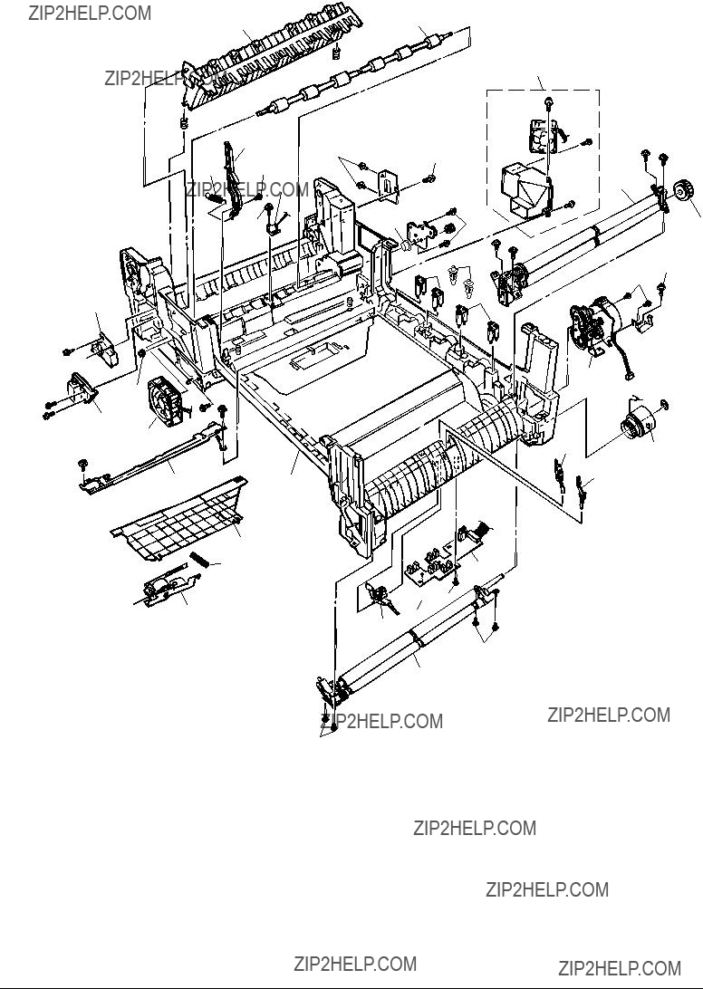
3.PARTS REPLACEMENT
This section describes the procedure for replacing the parts, assemblies and units in the field. The replacing procedure is given for detachment. To attach, use the reverse procedure.
3.1Precautions in Replacing Parts
(1)Before replacing the parts, be sure to remove the AC cable and the interface cable.
(a)To remove the AC cable, always use the following procedure. 1 Flip the power switch of the printer off (to ???O???).
2 Pull the AC inlet plug of the AC cable out of the AC receptable. 3 Remove the AC cable and the interface cable from the printer.
(b)To connect the printer again, always use the following procedure. 1 Connect the AC cable and the interface cable to the printer. 2 Insert the AC inlet plug into the AC receptacle.
3 Flip the power switch of the printer on (to ???I???).
(2)Do not disassemble the printer so long as it operates properly.
(3)Minimize the disassembly. Do not detach parts other than those shown in the replacing procedure.
(4)For maintenance applications, use designated tools.
(5)Follow the order instructed to disassemble the printer. Incorrect order may damage the parts.
(6)Small parts such as screws and collars tend to get lost, so temporarily replace them in their original positions.
(7)When handling ICs and circuit boards such as microprocessors, ROMs and RAMs, do not use gloves that are likely to have static.
(8)Do not place the printed circuit boards directly on the printer or the floor.

[Maintenance Tools]
Table
Table

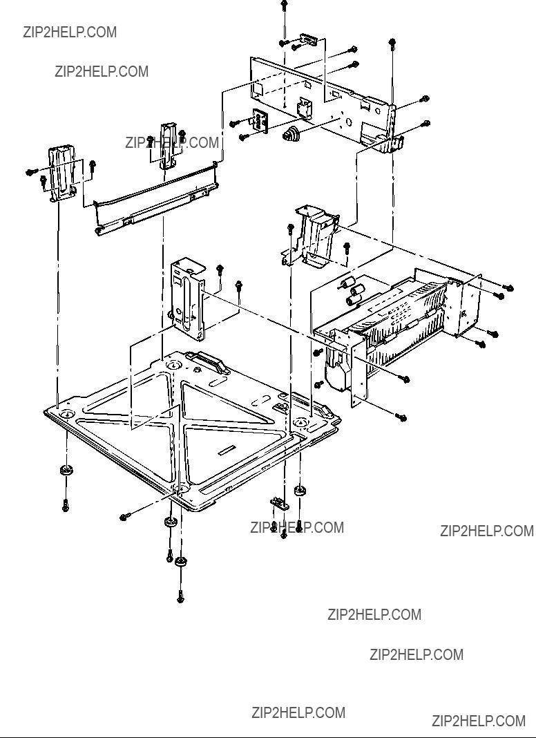
3.2Parts Layout
Figure 3.1

[Top Cover Assy]
Figure 3.2
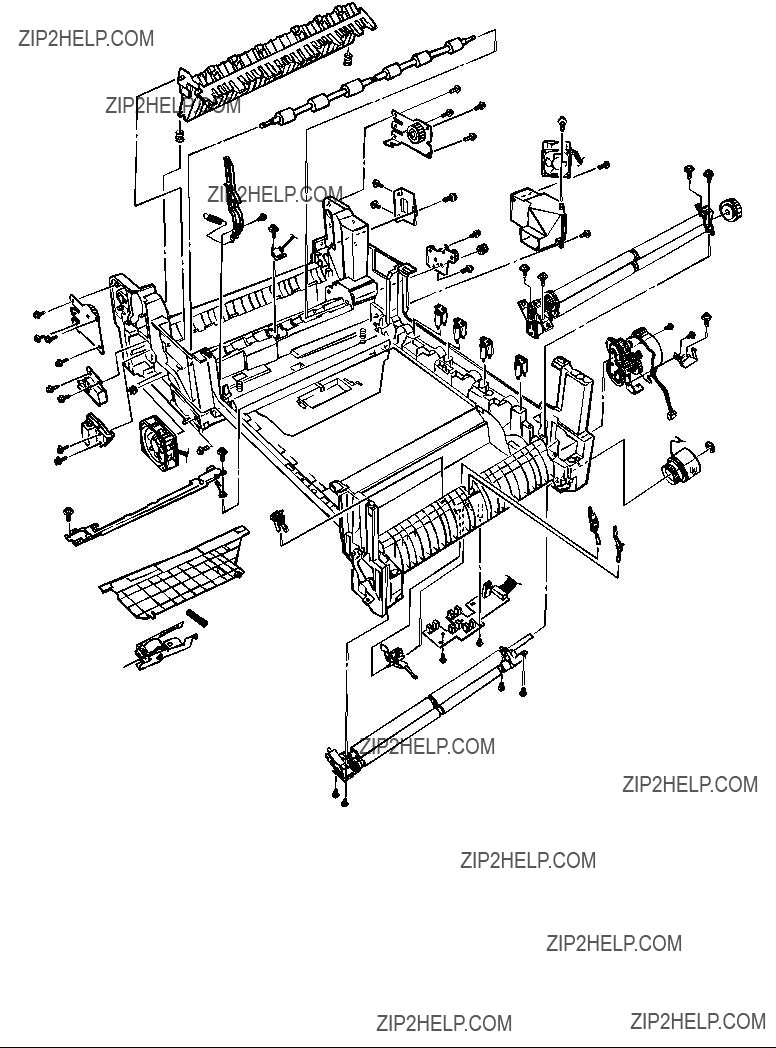
[Printer
Figure 3.3

[Printer
Figure 3.4
[Cassette Guide Assy (L), (R)]
Figure 3.5


[Duplex Unit]
D
C
B
A
D
C
E
B
E

 A
A
Figure 3.6

3.3Replacing Parts
This section describes how to replace the parts and assemblies illustrated below.
40841302
Fuser Latching Handle (L) (3.3.29) 41628301
Fuser Latching Handle Spring (3.3.29) 40841601
Entrance Sensor Actuator #1 (3.3.24) 41578501
Entrance Sensor Actuator #2 (3.3.26) 40841801
Entrance Sensor Actuator #3 (3.3.26) 41621801
Registration Shutter Solenoid Assy 41488801
Registration Shutter 41589401
Registration Shutter Spring 41641701
Fuser Driver
Fuser Exit Roller (3.3.27)
Fuser Exit Roller Bushing (L) (3.3.27)
Fuser Exit Roller Bushing (R) (3.3.27) 41189701 ??? 4
Drum Contact Assy (3.3.14) 41258301
Entrance Sensor PWB (3.3.25) 41491001
Color Registration Sensor Assy (3.3.19) 41073601
Exit Sensor Assy (3.3.28) 41483701
Main Motor FAN Assy (3.3.27)
40861001 ??? 8
LED Assy Spring (3.3.2) 41257902
LED Control PWB (Y71) (3.3.4) 41349801
Stack Full Sensor (3.3.4) 41349301 ??? 4
Eject Roller (3.3.4) 41484501
Control Panel Assy (3.3.4) 2381005P0015
Control Panel Tape Harness (3.3.4) 41514101
LED Harness K 41514102
LED Harness Y 41514103
LED Harness M 41514104
LED Harness C 41328402
Top Cover Handle (3.3.5) 41277602
Top Cover Latch (3.3.5) 40861401 ??? 2
Top Cover Latch Spring (3.3.5) 41484701
Eject Guide Assy (3.3.6)
3.3.1Top cover
(1)Open the top cover Assy.
(2)Remove the nine screws 1 to detach the top cover 2.
2
 1
1

 1
1
1

3.3.2LED Assy/ LED Assy spring
(1)Open the top cove 1.
(2)Remove the three cables, and unhook the LED Assy 2at the two places to demount it (The two springs 3 become detached together with the LED Assy 2).
(3)Detach the LED connector 4.
When assembling, attach the LED connector 4 to the LED head and insert the flat cable.
1
3
3
2
4
4

3.3.3Top cover unit
(1)Remove the top cover (see section 3.3.1).
(2)Remove the rear cover (see section 3.3.12).
(3)Remove the front cover (see section 3.3.11).
(4)Remove the electrical chassis (see section 3.3.21).
(5)Unscrew the screws 1 and 2 to remove the limiters (F) 3 and (R) 4.
(6)Remove the inner shaft 5, then the top cover unit 8 (The inner springs 6 and 7 become detached).
8
6
2
1

3

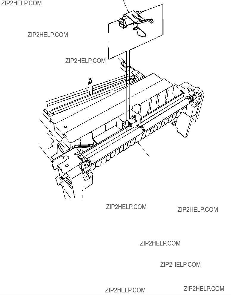
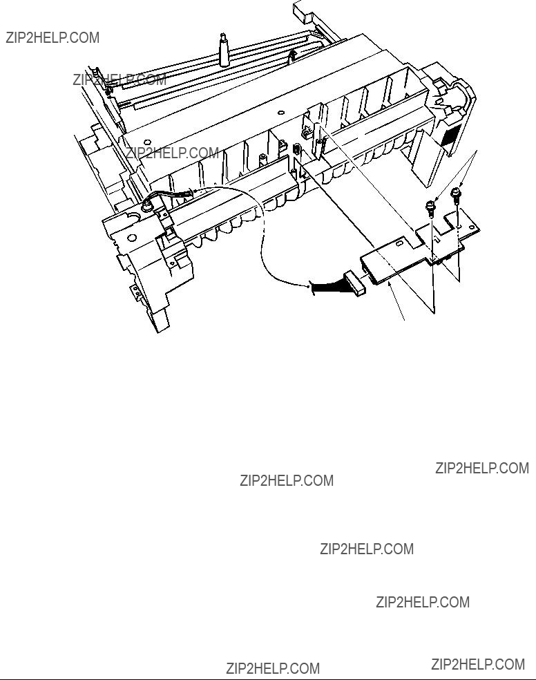
3.3.4Control panel Assy/ Control panel bezel/ LED control PWB/ Toner sensor/ Stack full sensor/ Control panel tape harness/ Eject roller
(1)Detach the control panel bezel 1.
(2)Remove the screws 2 to demount the control panel 3.
(3)Detach the control panel tape harness 4.
(4)Remove the screws 6, unhook the connector 7 and demount the LED control PWB 8.
(5)Unscrew the screws 9 to remove the plate 0.
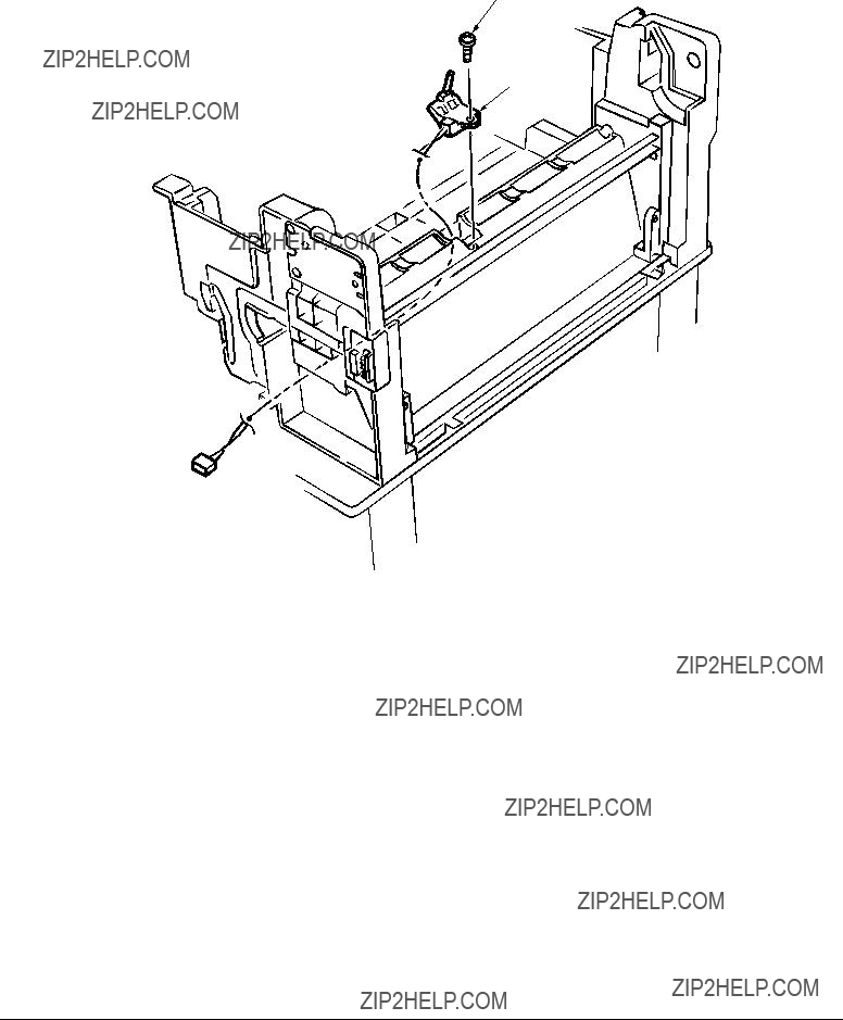
(6)Disengage the claw to demount the toner sensor A.
(7)Demount the stacker full sensor B.
(8)Unscrew the eject sensor bracket C, D.
1
9 9 


0
3.3.5Top cover handle/ Top cover latch/ Top cover latch spring
(1)Remove the two screws 1 to detach the top cover handle 2 and disengage the top cover latch 3 (The two top cover latch springs 4 become detached).
1
4
1
4

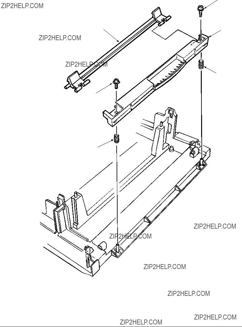
3.3.6Eject guide Assy
(1)Remove the seven screws 1 to detach the eject guide Assy 2.
2

3.3.7Cassette Assy/ Blind cover/ Side cover R Assy
(1)Detach the cassette Assy 1.
(2)Disengage the blind cover 2 at the two places to detach it.
(3)Unscrew the two screws to remove the stopper 4.
(4)Disengage the claw on the left support of the side cover R to detach the side cover R.
4 5
5
2
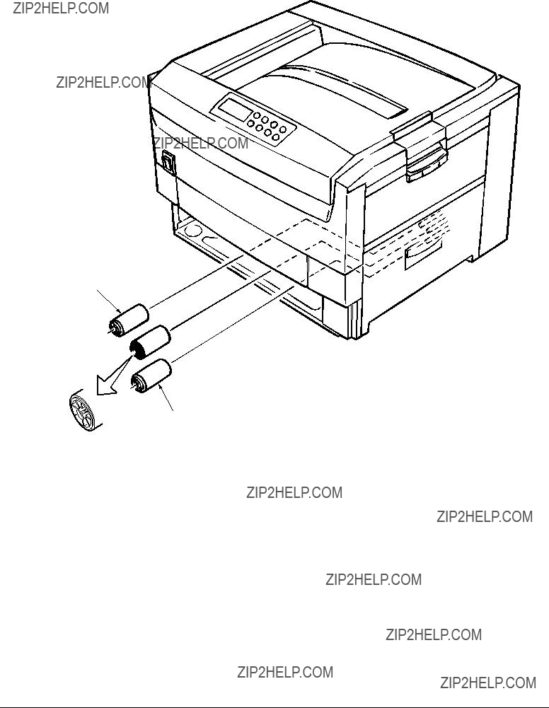
3.3.8Feed rollers
(1)Remove the cassette.
(2)Unlatch and demount the feed rollers 1.
1
1


1

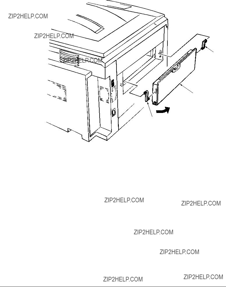
3.3.9Left side cover
(1)Remove the four screws 1 to detach the left side cover 2.
2
 1
1


 1
1
3.3.10
(1)Open the
2
1
2
3.3.11Front cover
(1)Open the top cover 1.
(2)Disengage the claws and remove the blind cover 2.
(3)Unscrew the six screws 4 to detach the front cover 3.
1
4
4
4
4

 3 4
3 4
2

3.3.12Rear cover
(1)Open the top cover 1,
(2)Remove the five screws 3 and 4 to detach the rear cover 2.
4
3
3
1
2

3.3.13Multipurpose tray Assy/ Multipurpose tray cover Assy/ Links/ Multipurpose tray top cover/ Multipurpose tray drive gear
(1)Remove the rear cover (see section 3.3.12).
(2)Remove the front cover (see section 3.3.11).
(3)Unscrew the three screws 1 to detach the multipurpose tray top cover 2.
(4)Unscrew the two screws 3 and remove the connector to detach the multipurpose tray 4.
(5)Disengage 4 and 5 to detach the multipurpose tray cover Assy 5 (the links 7 become detached).
(6)Unhook and detach the multipurpose tray drive gear 8.
1
4  6
6
5


 3
3
3.3.14Drum contact Assys
(1)Insert a flatblade screwdriver between the printer case and the drum contact Assy 1 to demount the drum contact Assy.
1

3.3.15Registration roller Assy (A)/ Registration drive gear (A)
(1)Remove the front cover (see section 3.3.11).
(2)Remove the rear cover (see section 3.3.12).
(3)Remove the multipurpose tray (see section 3.3.13).
(4)Unscrew the four screws 1 to demount the registration roller Assy (A) 2.
(5)Remove the E ring 3 to detach the registration gear (A) 4.
1
4 3
2
1

3.3.16Registration roller Assy (B)
(1)Remove the cassette Assy.
(2)Remove the front cover (see section 3.3.11).
(3)Remove the rear cover (see section 3.3.12).
(4)Remove the electrical chassis (see section 3.3.21).
(5)Remove the registration clutch (see section 3.3.17).
(6)Remove the printer chassis (see section 3.3.23).
(7)Unscrew the four screws and pull out the registration Assy (B) 2 in the arrow direction.
1
2
1


 1
1

3.3.17Registration clutch, Registration motor Assy
(1)Remove the left side cover (see section 3.3.9).
(2)Remove the electrical chassis (see section 3.3.21).
(3)Remove the connector and the E ring 1, then screws 3and 4, and then the earth plate 5.
(4)Remove the connector and unscrew the two screws 6to demount the registration motor Assy
7.


 5
5 

 4
4
6
2
1

3.3.18Cooling fan
(1)Unhook the connector 1, and remove the screws 2 and the cooling fan 3.
1
 2
2
 3
3
air direction

3.3.19Color registration sensor Assy
(1)Remove the two screws 1and the three connectors to demount the color registration sensor Assy 2.
(2)Remove the earth plate B 3.
1
1 2
1
 2 3
2 3
4

3.3.20Duplex guide Assy
(1)Unlatch and demount the duplex guide Assy 1.
(2)Remove the springs 2.
1
2
2
Main chassis (L side)
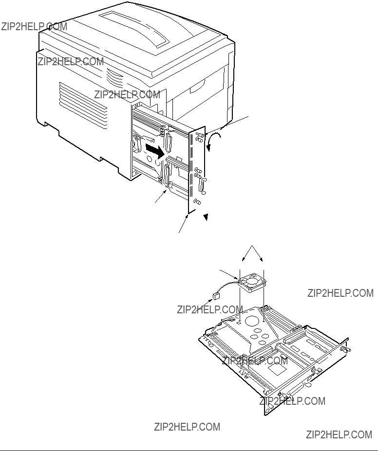
3.3.21Electrical chassis/ Electrical chassis cooling fan
(1)Unscrew the five screws 1 and two screws 2 to remove the plate A 3.
(2)Unscrew the
(3)Remove the printer engine controller PWB (see section 3.3.22).
(4)Unscrew the eleven screws 6 to detach the electrical chassis 7.
(5)Unscrew the two screws 8 to demount the electrical chassis cooling fan 9.
1
1
1 2 3 
 air direction
86
6 5
4

3.3.22Printer engine controller PWB
(1)Remove the rear cover (see section 3.3.12).
(2)Remove the electrical chassis and the electrical cooling fan (see section 3.3.21).
(3)Remove the five screws 1 and all the connectors to demount the printer engine controller PWB 2.
2
1
 1
1

3.3.23Printer unit chassis
(1)Unscrew the screw 1 and remove the AC switch Assy 2.
(2)Remove the four black screws 3 and six screws 4 to detach the printer unit chassis 5.
3
3
 4
4
3 


 5
5
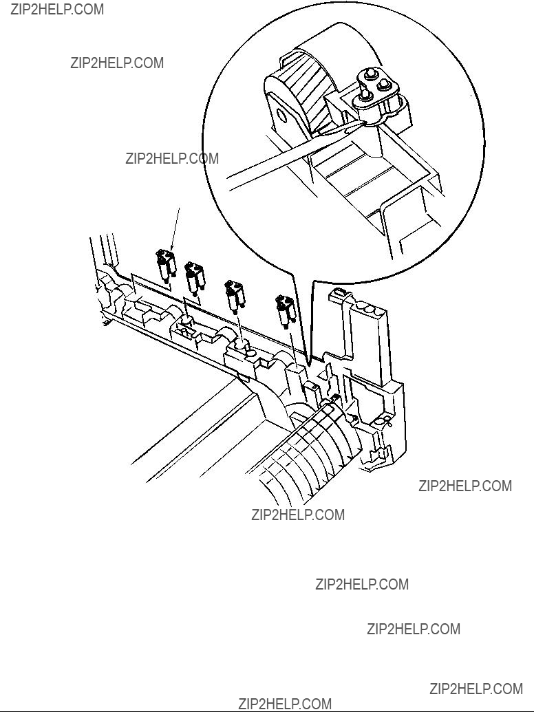
3.3.24Entrance cassette sensor actuator
(1)Remove the printer unit chassis (see section 3.3.23).
(2)Turn over the main chassis.
(3)Remove the two clamps with tweezers to demount the entrance cassette sensor actuator 1.
1
Main chassis
3.3.25Entrance sensor PWB
(1)Remove the registration roller Assy (B) (see section 3.3.16).
(2)Remove the two screws 1 to demount the entrance sensor PWB 2.
 1
1
2

3.3.26Entrance MT sensor actuator and Entrance belt sensor actuator
(1)Remove the entrance sensor PWB (R71) (see section 3.3.25).
(2)Unlatch and detach the entrance MT sensor actuator 1.
(3)Unlatch and detach the entrance belt actuator 2.
2

 1
1

3.3.27Main motor fan/ Fuser eject roller
(1)Unscrew the two screws 1 to remove the fan Assy 2.
(2)Unscrew the fuser eject roller contact 4.
(3)Remove the fuser drive gear 5.
(4)Unscrew the fuser drive gear Assy 8.
(5)Remove the screws and washers 0 to demount the fan A.
(6)Unlatch and detach the fuser eject roller bearing (L) B and fuser eject roller C.
9
0
A
C
 9 0
9 0
B
8
5

1
1
3.3.28Eject sensor Assy
(1)Remove the fuser eject roller (see section 3.3.27).
(2)Remove the screw 1 and connector 2 to demount the (red/blue) eject sensor Assy 2.
1
2

3.3.29Fuser latching handle (L)
(1)Remove the latching handle spring 1.
(2)Unscrew the fuser latching handle (L) 3.
3
1
2
3.3.30Belt motor Assy
(1)Remove the fuser latching handle (R) (see section 3.3.32).
(2)Unscrew the two screws 1 to detach the two connector 2.
(3)Demount the belt motor Assy 3.
1
1

 3 2
3 2


3.3.31Fuser latching handle (R)
(1)Remove the printer unit chassis (see section 3.3.23).
(2)Remove the E ring 1.
(3)Remove the fuser latching handle spring 2 to detach the fuser latching handle (R) 3.
3
1 


 2
2

3.3.32Main motor Assy
(1)Remove the belt motor Assy (see section 3.3.30).
(2)Remove all the connectors.
(3)Remove the two screws 1 to demount the main motor Assy 2.
1
1
2

3.3.33Contact Assy/ Side plate Assy
(1)Remove the printer unit chassis (see section 3.3.23).
(2)Remove the four screws 1 to detach the side plate Assy 2.
(3)Remove the three screws 3 to detach the contact Assy 4.
23
1


4

3.3.34Low voltage power supply
(1)Remove the printer unit chassis (see section 3.3.23).
(2)Unhook the connector 1.
(3)Remove the eight screws 2 to demount the low voltage power supply 5.
1 2 7 8
3
2


6
5
 2
2
0


 0 0
0 0 


A
9
3.3.35High voltage power supply
(1)Remove the contact Assy (see section 3.3.33).
(2)Unhook the connector of the high voltage power supply 2.
(3)Remove the two screws 1to detach the high voltage power supply 2and the tape harness
3.
1
3
1
2

3.3.36Main feed Assy
(1)Remove the printer unit chassis (see section 3.3.23).
(2)Remove the low voltage power supply and high voltage power supply (see sections 3.3.34 and 3.3.35).
(3)Unscrew the five screws 1 to remove the lower plate 2.
(4)Unscrew the six screws 3 to demount the main feed Assy 4.
(5)Unscrew the screws 5 to detach the cable and then the PCB size board 6.
(6)Unscrew the screw 7 to detach the duplex connector 8.
(7)Unscrew the screws 9 to detach the second tray connector 0.
1
1
2
8 
7 


 6
6


5


 0 4
0 4
9


 3
3
 3
3
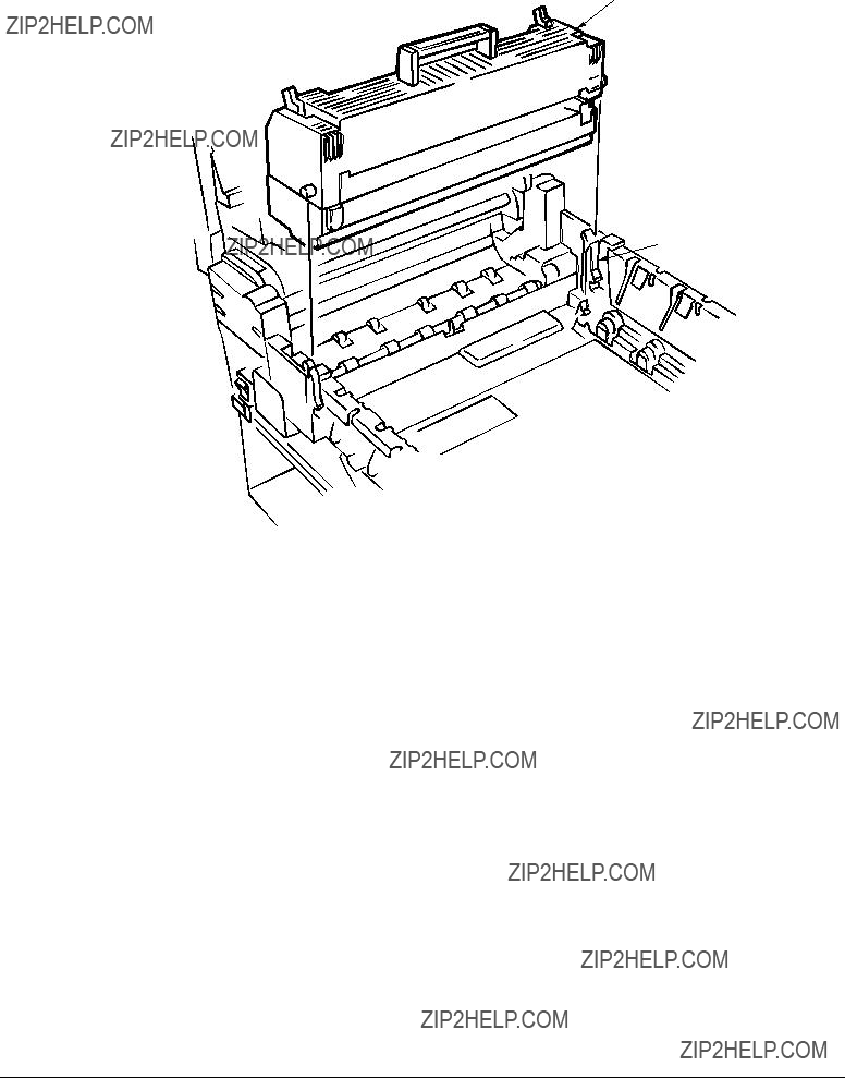
3.3.37Fuser unit
(1)Open the top cover 1.
(2)Push the right and left fuser levers (blue) 2in the arrow direction to detach the fuser unit 3.
3
2

3.3.38Belt unit
(1)Open the top cover 1.
(2)Remove the I/D unit.
(3)Push the lever (blue) 2in the arrow direction, raise the handle (blue) and detach the belt unit
3.
3
1

2 
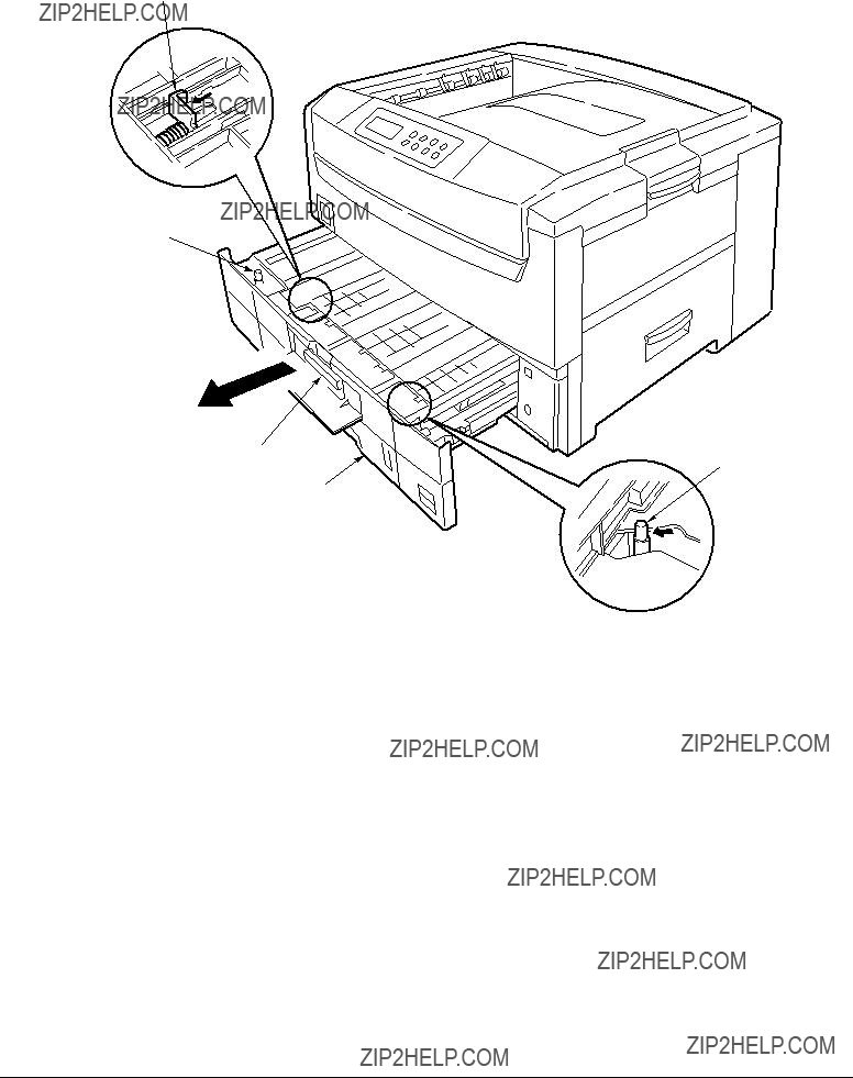
3.3.39Duplex unit
(1)Remove the cassette Assy, the front cover and the front cover inner buffle.
(2)Unlatch the rear at the right and left and pull the duplex unit 1 toward the front.
4
5
1
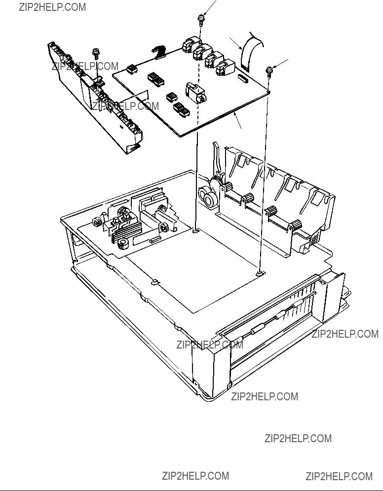
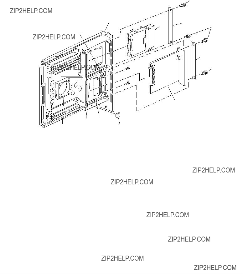
3.3.40CU Assy
(1)Pulling out Control Board
1.Loosen the two screws 1.
2.Pull the control board 2 out.
3.Place the control board 2 on a flat table.
(2)Detaching Fan
1.Remove the connector 3.
2.Remove the two screws 4.
3.Detach the fan 5.
1
2


1 4
5 

3
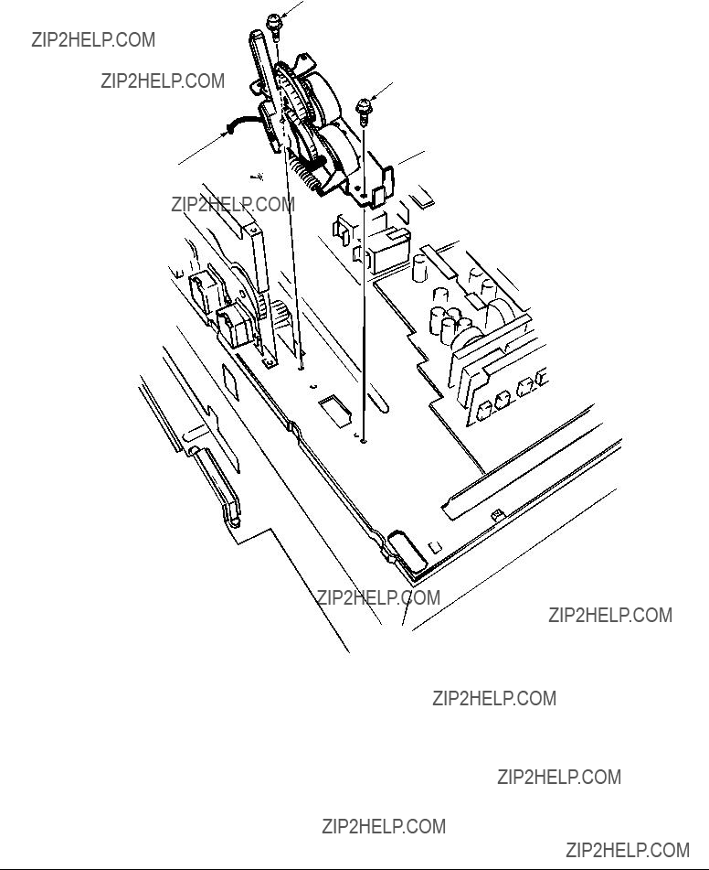
(3)Demounting CRM Board
1.Remove the three screws 6 to detach the fan bracket 7.
2.Remove the four screws 8 to detach the plate support 9 and the guide rail 0.
3.Remove the two screws A to detach the guide rail B.
4.Remove the two screws C and three screws D, then demount the CRM board E.
6
7
8
6
E


 8
8
D
0
9 8
D
B
8
C
8

4.ADJUSTMENT
Adjustments are carried out by key operations on the operator panel.
The maintenance menu is included in the general menu of this printer. Choose the maintenance menu for adjustment.
4.1Maintenance Menu and Its Functions
The general menu has the category, MAINTENANCE MENU.
The items adjustable in this menu are shown below.
Maintenance Menu

4.2Short Plug Settings
The CRM board has five short plugs that can be set as follows:
Short Plug (WE1,3, 5 and 7)
Sets flash ROM DIMM to connect WE signals.
The
Short Plug (DIMM2)
Sets the banks of ROM DIMM Slot B.
4.3Printing Singly Using
Menu Map Printing
Prints the program versions, controller block, and other printer configuration and settings. Operation: (Press of Switch)
Without HDD: ???0?????? ???3?????? ???3???
With HDD: ???0?????? ???0?????? ???3?????? ???3???
File List Printing
Prints a list of files stored on a HDD or in ROM.
Operation: (Press of Switch)
Without HDD: ???0?????? ???3?????? ???1?????? ???3???
With HDD: ???0?????? ???0?????? ???3?????? ???1?????? ???3???
Font List Printing (PCL)
Prints a list of PCL fonts.
Operation: (Press of Switch)
Without HDD: ???0?????? ???3?????? ???1?????? ???1?????? ???3???
With HDD: ???0?????? ???0?????? ???3?????? ???1?????? ???1?????? ???3???
Font List Printing (PS)
Prints a list of PS fonts.
Operation: (Press of Switch)
Without HDD: ???0?????? ???3?????? ???1?????? ???1?????? ???1?????? ???3???
With HDD: ???0?????? ???0?????? ???3?????? ???1?????? ???1?????? ???1?????? ???3???
Demo Printing
Prints the demo patterns for destinations.
Operation: (Press of Switch)
Without HDD: ???0?????? ???3?????? ???1?????? ???1?????? ???1?????? ???1?????? ???3???
With HDD: ???0?????? ???0?????? ???3?????? ???1?????? ???1?????? ???1?????? ???1?????? ???3???
Ethernet Board
When equipped with an Ethernet board, the printer runs diagnostic checks on itself by holding the SW on the Ethernet board down for two seconds or more, and prints the results.

4.4Adjustment after Part Replacement
Adjustment to be implemented after each part replacement is described below.
Adjustment and correction of color registration are always required for each part replacement.
*Note: When the EEPROM of the PU (K73 Board) is replaced to a new one, color balance must be adjusted.

4.5Color Balance Adjustment
Color balance has been adjusted appropriately when a printer is shipped from the plant. However, it may be out of the appropriate balance during use. In such a case, color balance should be modified.
Note: Density of each color depends on each other. Therefore, adjustment must be repeated several times to reach the correct color balance.
(1)Set letter paper in the tray specified on the operator panel.
(2)Press )several times to display [COLOR MENU].
(3)Press 1or 5to display [COLOR BALANCE CORRECTION/PATTERN PRINT].
(4)Press 3to start test printing.
(5)Press 1to display [COLOR BALANCE CORRECTION/RESET].
(6)Choose the number of the color closest to the [(] part on the test pattern.
If the selected color is [00], the color balance is correct and no adjustment is required. If it is not [00], the color balance should be adjusted in the procedures below.
(7)Press 2or 6several times to display the value selected in Step (6).
(8)Press 3to start test printing.
(9)Repeat the steps (6)~(8) to approximate the color at the [(] part on the test pattern to [00] as much as possible.
(10)Press 4to display [ON LINE].


4.6EEPROM Replacement after CRM Board and K73 Board Replacement
When replacing the CRM Board or K73 Board, the EEPROM must be removed and
If the EEPROM used by the user is broken and not suitable for further use, the EEPROM on the new board may be used.

5.REGULAR MAINTENANCE
5.1Consumables to be Regulary Replaced
It is recommended that a user should replace the consumables below according to the replacement standard. (If not replaced, print quality is not assured or it may result in a failure.)
The above consumables replacement may be performed by a user.
5.2Cleaning
The inside and outside of this printer should be cleaned with a hand vacuum cleaner, if necessary.
Note: Do not touch the Image drum terminal, LED lens array and LED head connectors.
5.3Cleaning of LED Lens Array
When a longitudinal white band or stripes (that is, void or light printing) appear on a printed paper surface, the LED lens array should be cleaned.
Note: The LED head cleaner must be used to clean the LED lens array. (The LED head cleaner is included in the Toner cartridge box.)
White band, white stripes (Void or light printing)
5.4Cleaning of
When papers are not fed normally, the
Note: Clean it with a soft cloth and alcohol. Be cautious not to damage the roller surface.

6.TROUBLESHOOTING PROCEDURES
6.1Tips for Troubleshooting
(1)Check the basic check points covered in the user???s manual.
(2)Gather as much information on the problem from the customer as possible.
(3)Perform inspections in conditions close to those in which the problem had occurred.
6.2Check Points before Correcting Image Problems
(1)Is the printer being run in proper ambient conditions?
(2)Have the consumables toner and image drum cartridges been replaced properly?
(3)Is the paper normal? See paper specifications section.
(4)Has the image drum cartridge been loaded properly?
6.3Tips for Correcting Image Problems
(1)Do not touch, or bring foreign matter into contact with the image drum surface.
(2)Do not expose the image drum to direct sunlight.
(3)Keep hands off the fuser unit as it is heated during operation.
(4)Do not expose the image drum to light for longer than 3 minutes at room temperature.
6.4Preparation for Troubleshooting
(1)Operator panel display
The failure status of this printer is indicated on the LCD (liquid crystal display) of the Operator panel.
Take the proper corrective action according to the message displayed on the LCD.
6.5Troubleshooting Flow
If a problem should develop in this printer, troubleshoot in the following procedure.
Problem
Image problem (and a problem that does not result in LCD message indication.)
Perform troubleshooting with the troubleshooting flow chart. See 6.5.2.
Perform troubleshooting with the troubleshooting flow chart. See 6.5.3.
6.5.1LCD Message List
The printer indicates a Service Call Error message on the LCD as shown below, detecting an unrecoverable error.
Service Call nnn : Error
Note: nnn is an error code.
When the Service Call message is displayed, the error information corresponding to the error code appears on the lower line of the LCD. The meaning and solutions of each error code are listed in the Table
Table

Table

Table

Table

Table

6.5.2LCD message troubleshooting
(1)LCD Message
The message on the LCD (liquid crystal display) tells the problem situation of the printer. Implement the appropriate troubleshooting base on the message.
Note: When replacing the engine board (L73 PWB), demount the EEPROM chip from the old board and remount it on the new one.

1The printer does not work normally after turned on.
???Turn off the printer, wait a few seconds, then turn it on again.
??? Is 


 displayed on the LCD (for about 1 second)?
???
??? Yes
???
??? Yes
No Check the connection of the POWER connector, or replace the
Replace the engine board.
Are the following voltages supplied to the PU connector of the main board?

???Does the jam occur soon after the printer is turned on?
???
??? Yes
???
??? No
??? Yes
Check the signal cable connection, or replace the engine board (K73 PWB).
Does the paper jam occur immediately after the paper is fed?
Does the paper reach the entrance cassette sensor or the entrance MT sensor? Yes Go to A .
???
??? No
???
??? No
Yes
???
??? No
No
???
??? Yes
No
???
??? Yes
Replace the feed roller or the Retard Pad assy in the paper tray.
Is the feed motor rotating?
Replace the feed roller.
Is the resistance of the feed motor at the rated value (approx. 7.9 or 8.4 ??? )? Replace the feed motor.
Is +32V supplied to the POWER connector Pins 7~10 on the engine board? Replace the
Check gear engagement and cable connection, or replace the engine board.

???Does the paper jam occur immediately after the printer is powered on?
???
??? No
???
??? No
??? No
Replace the multipurpose tray assembly.
Does the registration motor rotate properly?
Is +32V supplied to the POWER connector Pins 7~10 on the engine board? No Replace the

???Does the paper jam occur immediately after the printer is powered on?
??? Yes Is the paper jammed at the entrance belt sensor? Yes Remove the jammed paper.
???
???
A No Does the lever of the write sensor work right?
No Replace the lever of the write sensor.
???
??? No
???
Does the paper jam occur immediately after paper is fed? Yes Does the paper reach the write sensor?
Yes Go to A.
???Does the paper jam occur immediately after the printer is powered on?
???
??? No
??? No
Dose the heat motor rotate properly?
Is the resistance of the heat motor at the rated value (approx. 7.9 ??? )? No Replace the heat motor.
???
??? Yes
??? No
Does the paper separator operate normally?
Does the paper separator solenoid work normally?
No Check the cable connection, or replace the solenoid or the engine board.

???Does the paper jam occur immediately after the printer is turned on?
???Yes Is the DUPLEX motor rotating?
No Replace the DUPLEX motor.
???
??? Yes Check gear engagement or replace the DUPLEX board (V73 PWB). Replace the DUPLEX unit.

3Paper Size Error
???Is paper in the specified size used?

4Image Drum Unit (IDU) Up/Down Error
???Turn off the printer, wait a few seconds, then turn it on again.
???Does each drum unit rotate properly while printing?
PWB), or replace the engine board.

5Fuser Unit Error
???Does the fuser error occur immediately after the printer is turned on?
A
??? Yes Does the heat roller thermistor have a open or short circuit? (See Figure 6.1.) (at room temperature 0 ?? C~ 43 ?? C, approx. 190 ~ 980 ??? )
Yes Replace the fuser unit.
???
??? No Does the
Yes Replace the fuser unit.
Does the fuser error occur about 3 min. after the printer is turned on? Go to A .
???
??? No
???
??? No
No
???
??? Yes
Replace the fuser unit.
Does AC voltage appear between CN1 connector Pin 1 and Pin3 of the
Replace the
Replace the fuser unit.
Halogen Lamp
Heat Roller Thermistor
Bottom part of Fuser Unit
Figure 6.1

6Fan Motor Error
???Does the fan of the

6.5.3Image troubleshooting
When the printout images are not satisfactory as shown below, follow the troubleshooting procedures given in this section.
Figure 6.2

1Light or blurred images or images in inappropriate color tone on the whole printout area
(Figure 6.2- A )
???
??????
???
???
???
???
???
???
Is toner low? (Is the message "Toner Low" displayed?)
Notes: 1. When replacing the engine board (K73 PWB), demount the EEPROM chip from the old engine board and remount it on the new one.
2. In case the EEPROM chip is not replaced, see Item (2) in Sec. 6.5.2.

2Dark background (Figure 6.2- B )
???Was each ID exposed to external light for a long time?

3Blank paper (Figure 6.2- C )
???Is each LED head assembly connected to the junction board (Y71 PWB) and Engine board (K73 PWB)correctly?
No Check the cable connection the LED assembly with the junction board (Y71 PWB) and engine board.
???
??? Yes Is +3.8V supplied to the following POWER connector pins on the junction board (Y71 PWB)? +3.8V: Pin 1, 2, 3, 4, 5, 6, 7, 8
??? Yes Is +3.8V supplied to the following cable connector pins between the junction board (Y71 PWB) and each LED head assembly?
YPOW connector Pin 3 : LED head assembly yellow
MPOW connector Pin 3 : LED head assembly magenta
CPOW connector Pin 3 : LED head assembly cyan
BPOW connector Pin 3 : LED head assembly black No Replace the junction board (Y71 PWB).
???
??? Yes
???
??? No
No
???
??? Yes
Check the cable connection, or replace the LED head assembly.
Is +32V supplied to the POWER connector pins of the engine board (K73 PWB)? +32V: Pin 7, 8, 9, 10
Check the cable connection, or replace the
Is +32V supplied to the HVOLT connector Pin 5 of the engine board (K73 PWB)?
Notes: 1. When replacing the engine board (K73 PWB), demount the EEPROM chip from the old engine board and remount it on the new one.
2. In case the EEPROM chip is not replaced, see Item (2) in Sec. 6.5.2.
4Band/stripes in black or color in the longitudinal direction (Figure 6.2- D )
???Is each LED head assembly connected to the junction board (Y71 PWB) correctly?
No
???
??? Yes
Yes
???
??? No
Yes
???
??? No
No
???
??? Yes
Yes
???
??? No
No
???
??? Yes
Connect the LED head assembly to the junction board correctly.
Check the cable connection, or replace the LED head assembly. Recovered?
End
Check the cable connection, or replace the junction board (Y71 PWB). Recovered?
End
Is the engine board (K73 PWB) connected with the junction board (Y71 PWB) correctly?
Connect the engine board with the junction board correctly.
Check the cable connection, or replace the engine board (K73 PWB). Recovered?
End
Is each ID terminal connected to the contact assembly correctly? (See Figure 6.3.)
Connect the ID terminals with the contact assembly correctly.
Replace the ID unit.
Notes: 1. When replacing the engine board (K73 PWB), demount the EEPROM chip from the old engine board and remount it on the new one.
2. In case the EEPROM chip is not replaced, see Item (2) in Sec. 6.5.2.

5 Band/stripes in white or irregular color in the longitudinal direction (Figure 6.2- F )
???Is each LED head lens contaminated?
???
??? Yes
Notes:
Replace the ID unit.
1.When replacing the engine board (K73 PWB), demount the EEPROM chip from the old engine board and remount it on the new one.
2.In case the EEPROM chip is not replaced, see Item (2) in Sec. 6.5.2.

6 Poor fusing (Images are blurred or peeled off when touched with a hand.)
???Is the specified paper used?
Notes: 1. When replacing the engine board (K73 PWB), demount the EEPROM chip from the old engine board and remount it on the new one.
2. In case the EEPROM chip is not replaced, see Item (2) in Sec. 6.5.2.

7Cyclical printout defects (Figure 6.2- E )
Note: After replacement of the ID unit, fuser unit or belt cassette unit, the corresponding counter will be reset.

8Missing characters
???Is the LED head lens contaminated?
Notes: 1. When replacing the engine board (K73 PWB), demount the EEPROM chip from the old engine board and remount it on the new one.
2. In case the EEPROM chip is not replaced, see Item (2) in Sec. 6.5.2.

9Color Misalignment
???Are any of the following gears broken? (Gear assy of ID unit, Multipurpose Tray, belt unit and belt motor)
Notes: 1. When replacing the engine board (K73 PWB), demount the EEPROM chip from the old engine board and remount it on the new one.
2. In case the EEPROM chip is not replaced, see Item (2) in Sec. 6.5.2.

0 Printout colors different from the original
???Are the LED head lens contaminated?
Notes: 1. When replacing the engine board (K73 PWB), demount the EEPROM chip from the old engine board and remount it on the new one.
2. In case the EEPROM chip is not replaced, see Item (2) in Sec. 6.5.2.

Ground
Charge Roller
Developing Roller
Toner Supply Roller
Figure 6.3

2.Rev 41388601TH
/ 129

2.Rev 41388601TH
/ 130
2.Rev 41388601TH
/ 131
Brown
4

2.Rev 41388601TH
-
+
1
Red
2
Black
0 V
1
Red
+32 V
3
Yellow
2
Black
/ 132
0 V

2.Rev 41388601TH
/ 133
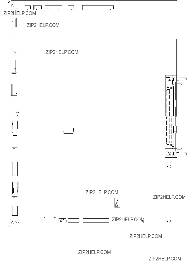
7.2Parts Layout on Boards
(1)Print Engine Controller PWB (K73)
ID
BELTHET
REG
TR10P
BELTSNS
JODEN
OPTN
CUIF

(2)Main Controller PWB: CRM
USB
CENT

(3)LED Control PWB
(4)Duplex Control PWB (V73- PWB)
(5)Control Panel PWB (X71- PWB)

(6)
JODEN
(7)Entrance Sensor PWB (R71- PWB)
INSNS2 INSNS1
FSNS
(8)Paper Size Sensing PWB PXC (B73- PWB)
CN11
(9)Sensor PWB
LIFT
CN1
HOP
(10) Option I/F PWB
MAIN1
SAVIF

8.PARTS LIST
25
22
24
21
21
8
21
21
 9
9
19
1
19
2
3
19
Figure

10
19

16
19
17 C
B
17 

C
C
17
A
C
B
18
A
 18
18
Figure
38
39
44
32
Figure
Table
Main Assembly

Table

Table

1
5
13
12
14
18
15
3
18
3
4
11
17
6
8 16
3


7
16
3

10
3


2
3
3 9
2
2
2
Figure

Table
Top Cover Assembly
12
22
7
39
20
39


23
21
42
8  13
13
10
11
9
39
16
6
185
17
19
 39 39
39 39
39
3
Figure

37 

 36
36
34
37
Figure

Table
Printer Unit Chassis

Table

11
11
11
11
12
12
12
7
Figure
12
13
12
2
6
5
2
2
12
12
12
13
12
15
16
13
Figure
18
12 12
3
4

Table
Paper Tray Guide

3
3
3
3
3
3
3
3
4
2
 3
3
3 D
C
B
A

 4
4
4
D
C
3
4
 4
4
E 3
B4
3
A
E
Figure

Table
Duplex Unit

23
24
1
7
25 7


7
9
 7
7
19
Figure

12
12
12
2
6
5
2
16
12
12
18*
4
12
3 *
13
* These parts are not attached to the lowest tray.
Figure

High Capacity Tray Unit, 2nd/3rd Tray Unit