i.LINK INTERFACE BOARD
INSTALLATION MANUAL 1st Edition
i.LINK INTERFACE BOARD
INSTALLATION MANUAL 1st Edition
! WARNING
This manual is intended for qualified service personnel only.
To reduce the risk of electric shock, fire or injury, do not perform any servicing other than that contained in the operating instructions unless you are qualified to do so. Refer all servicing to qualified service personnel.
! WARNUNG
Die Anleitung ist nur f??r qualifiziertes Fachpersonal bestimmt.
Alle Wartungsarbeiten d??rfen nur von qualifiziertem Fachpersonal ausgef??hrt werden. Um die Gefahr eines elektrischen Schlages, Feuergefahr und Verletzungen zu vermeiden, sind bei Wartungsarbeiten strikt die Angaben in der Anleitung zu befolgen. Andere als die angegeben Wartungsarbeiten d??rfen nur von Personen ausgef??hrt werden, die eine spezielle Bef??higung dazu besitzen.
! AVERTISSEMENT
Ce manual est destin?? uniquement aux personnes comp??tentes en charge de l???entretien. Afin de r??duire les risques de d??charge ??lectrique, d???incendie ou de blessure n???effectuer que les r??parations indiqu??es dans le mode d???emploi ?? moins d?????tre qualifi?? pour en effectuer d???autres. Pour toute r??paration faire appel ?? une personne comp??tente uniquement.
i.LINK and  are trademarks and indicate that this product is in agreement with
For the customers in the USA
This equipment has been tested and found to comply with the limits for a Class A digital device, pursuant to Part 15 of the FCC Rules. These limits are designed to provide reasonable protection against harmful interference when the equipment is operated in a commercial environment. This equipment generates, uses, and can radiate radio frequency energy and, if not installed and used in accordance with the instruction manual, may cause harmful interference to radio communications. Operation of this equipment in a residential area is likely to cause harmful interference in which case the user will be required to correct the interference at his own expense.
You are cautioned that any changes or modifications not expressly approved in this manual could void your authority to operate this equipment.
The shielded interface cable recommended in this manual must be used with this equipment in order to comply with the limits for a digital device pursuant to Subpart B of Part 15 of FCC Rules.
The device complies with part 15 of the FCC Rules. Operation is subject to the following two conditions: (1) this device may not cause harmful interference, and (2) this device must accept any interference received, including ineterference that may cause undesired operation.
For customers in Canada
This Class A digital apparatus complies with Canadian
Pour les utilisateurs au Canada
Cet appareil num??rique de la classe A est conforme ?? la norme
For the customers in Europe
This product with the CE marking complies with the EMC Directive (89/336/EEC) issued by the Commission of the European Community.
Compliance with this directive implies conformity to the following European standards:
???
???
E1 (residential), E2 (commercial and light industrial), E3 (urban outdoors) and E4 (controlled EMC environment, ex. TV studio).
Pour les clients europ??ens
Ce produit portant la marque CE est conforme ?? la Directive sur la compatibilit?? ??lectromagn??tique (EMC) (89/336/CEE) ??mise par la Commission de la Communaut?? Europ??enne.
La conformit?? ?? cette directive implique la conformit?? aux normes europ??ennes suivantes:
???
???
F??r Kunden in Europa
Dieses Produkt besitzt die
???
???
(St??rfestigkeit),
f??r die folgenden elektromagnetischen Umgebungen: E1 (Wohnbereich), E2 (kommerzieller und in beschr??nktem Ma??e industrieller Bereich), E3 (Stadtbereich im Freien) und E4 (kontrollierter EMV- Bereich, z.B. Fernsehstudio)
Section 1
Installation
The i.LINK interface board
In addition,
Beside this Installation Manual, the following manuals are prepared for
.Operation Manual
This manual is necessary for practical application and operation of
.Operation Guide (Supplied with
This manual serves as a quick reference.
.
This manual describes the information that premises the component service (periodic inspection, , periodic maintenance, diagnostics, parts replacement, adjustments, parts list, block diagrams, schematic diagrams, board layouts and others) to be used by system and maintenance engineers.
If this manual required, please contact your local Sony Sales Office/Service Center.
Procedure is different when installing
. To install
. To install
n
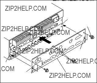
Before starting installation, be sure to turn off the POWER switch and disconnect the power cord. Then start the following procedures.

1.Remove the six M3 case stopper screws.
2.Remove the rear panel. n
Store the removed rear panel in a safe place so as not to lose it.
3.Insert the connector (CN601) on the
First, insert the connector (CN401) on the
4.Fix the
n
When tightening the screws, tighten the screws PWH2 x5 first of all screws.
CN401
CN601
IF panel
5.Insert the
6.Strongly push the connector panel both from the right and the left sides of the
7.Install the supplied rear panel for
n
Tighten the screws in the state that the two dowels are aligned with the holes (a) and (b) on the rear panel as shown in the figure.

1.Remove the six M3 case stopper screws.
2.Remove the rear panel. n
Store the removed rear panel in a safe place so as not to lose it.
3.Pull out the
4.Insert the connector (CN601) on the
First, insert the connector (CN401) on the
5.Fix the
n
When tightening the screws, tighten the screws PWH2 x5 first of all screws.
6.Insert the
7.Strongly push the connector panel both from the right and the left sides of the
8.Install the supplied rear panel for
n
Tighten the screws in the state that the two dowels are aligned with the holes (a) and (b) on the rear panel as shown in the figure.
Dowel
M3 case stopper screws

The material contained in this manual consists of information that is the property of Sony Corporation. Sony Corporation expressly prohibits the duplication of any portion of this manual or the use thereof for any purpose other than the operation or maintenance of the equipment described in this manual without the express written permission of Sony Corporation.
Le mat??riel contenu dans ce manuel consiste en informations qui sont la propri??t?? de Sony Corporation. Sony Corporation interdit formellement la copie de quelque partie que ce soit de ce manuel ou son emploi pour tout autre but que des op??rations ou entretiens de l?????quipement ?? moins d???une permission ??crite de Sony Corporation.
Das in dieser Anleitung enthaltene Material besteht aus Informationen, die Eigentum der Sony Corporation sind. Die Sony Corporation untersagt ausdr??cklich die Vervielf??ltigung jeglicher Teile dieser Anleitung oder den Gebrauch derselben f??r irgendeinen anderen Zweck als die Bedienung oder Wartung der in dieser Anleitung beschriebenen Ausr??stung ohne ausdr??ckliche schriftliche Erlaubnis der Sony Corporation.