ROUTING SWITCHER SYSTEM
DIGITAL VIDEO ROUTING SWITCHER
MULTI BIT RATE ROUTING SWITCHER
INSTALLATION MANUAL FOR SYSTEM SETUP 1st Edition (Revised 5)
ROUTING SWITCHER SYSTEM
DIGITAL VIDEO ROUTING SWITCHER
MULTI BIT RATE ROUTING SWITCHER
INSTALLATION MANUAL FOR SYSTEM SETUP 1st Edition (Revised 5)
IBM and AT are registered trademarks of International Business Machines, Inc. Windows is a registered trademark of Microsoft Corporation.
Windows NT is a trademark of Microsoft Corporation. Intel 80486SX is a trademark of Intel Corporation.
ROUTING SWITCHER SYSTEM (E)
Table of Contents
Manual Structure
2. Functions
5. System Settings
7.Change Information on

Manual Structure
Purpose of this manual
This is the Installation Manual (software) for the Sony routing switcher system (it is described as ???router system??? in this manual).
It contains information on the initial settings of the software when installing the units making up the digital router system.
This manual is intended for system and service engineers. But operators can also refer to it when setting and changing the system.
This manual is supplied with the following switchers.
Refer to installation manual and/or maintenance manual supplied with each unit for information on installing the hardware.
Contents
The following is a summary of the sections for understanding the contents of this manual.
1. System Overview
This section outlines the basic structure of the digital router system and control mechanism using the
2. Functions
This section explains the main functions of the digital router system.
3. Control Terminal
This section explains the key operation and image display of the control terminal.
Also describes how to use the personal computer as the control terminal.
4. Setup Procedure
This section explains the basic setting of
5. System Settings
This section explains the setting menus of the primary station and the secondary station and how to set each item in the menus, in detail.
Also it explains how to backup the table data.
6. Confirmation of Function
This section explains the error messages and how to check the operations of the system after completing setting.
7.Change Information on
Describes the change information accompanied with addition of functions and specification change.

Related manuals
In addition to this installation manual for system setup, the following manuals are also available for the main units making up the system.
(1)
.Operation Manual
(supplied with the
This manual explains the notes on operating, specifications, locations and functions.
.Installation Manual (Hardware)
(supplied with the
This manual contains information on setting up the hardware when installing.
.Maintenance Manual Part 1
(supplied with the
This manual contains information on the periodic maintenance and servicing information necessary for the principal block and board replacement.
.Maintenance Manual Part 2
(not supplied with the
This manual contains detailed information on the maintenance and servicing and their parts (adjustment, board layout, schematic diagram, detailed parts list and so on).
If this manual is required, please contact to Sony???s service organization.
.Protocol Manual
(not supplied with the
This manual contains information on the protocols used for controlling the routing switcher system.
The following manuals are available for protocols used to support.
Please contact to Sony???s service organization to obtain a copy of the manual.
ROUTING SWITCHER SYSTEM PROTOCOL AND SPECIFICATIONS (Sony cart protocol)
.
(not supplied with the
This manual contains technical outlines of a digital routing switcher system primary consisting of
If this manual is required, please contact to Sony???s service organization.
*1 : Common with
(2)
.Operation Manual (supplied with each unit)
This manual explains the notes on operating, specifications, locations and functions of each unit.
.Maintenance Manual (supplied with each unit)
This manual contains information on the installation, maintenance, and servicing of the unit and its parts (replacement, block diagram, adjustment, board layout, schematic diagram, detailed parts list and so on).
(3)
.Operation and Maintenance Manual (supplied with each unit)
This manual contains information on the proper operation and application of the unit, installation, maintenance, and servicing of the unit and its parts (replace- ment, block diagram, adjustment, board layout, schematic diagram, detailed parts list and so on).
(4)
.Operation Manual (supplied with each unit)
This manual explains the notes on operating, specifications, locations and functions of each unit.
.Installation Manual (supplied with each unit)
This manual contains information on setting up the hardware when installing each unit.
.Maintenance Manual (not supplied with each unit)
This manual contains detailed information on the maintenance and servicing of the unit and their parts (block diagram, adjustment, board layout, schematic diagram, detailed part list and so on).
(5)
.Operation Manual (supplied with the
This manual explains the notes on operating, specifications, locations and functions of each unit.
.Maintenance Manual Part 1 (supplied with the
This manual contains information on the periodic maintenance of
.Maintenance Manual Part 2 (not supplied with the
This manual contains detailed information on the maintenance and servicing of
If this manual is required, please contact to Sony???s service organization.

(6)
.Maintenance Manual Part 1 (supplied with
This manual describes how to install and maintain the
.Maintenance Manual Part 2 (available on request)
This manual describes the information that premises the service board parts replacement (board layouts, schematic diagrams and detailed parts list) of the
If this manual is required, please contact your local Sony Sales Office/Service Center.
(7)
.Operation Manual (supplied with each unit)
This manual explains the notes on operating, specifications, locations and functions of each unit.
.Maintenance Manual (available on request)
This manual contains information on the maintenance and servicing of the unit and its parts (replacement, block diagram, adjustment, board layout, schematic diagram, detailed parts list and so on).
Because functions are added and specifications are changed in the
For the contents of the
Section 1
System Overview
The system consists of the following units.
.Routing Switcher
It switches signals according to the command from the remote control unit. Varied switchers are available for different types of signals used (serial digital video, digital audio, time code,
etc.)
.Remote Control Unit
It switches signals and displays the name of the selected signal.
. Control Terminal
It sets the configuration and operation of the router system. It monitors the system in operation and displays the messages.
A unique control protocol called
Other than the
With cascade connection, several sets of routing switchers of
To operate this system, specified settings (making of table data) must be previously carried out using the control terminal.

Software Versions
This manual is intended for systems consisting mainly of the
When units other than these are used, some terminal displays will be different and some functions cannot be used. Therefore, please contact to Sony???s service organization to upgrade the version of your software.
n
Use the same version software for the same models of routing switcher or remote control units on the S- BUS data link. If different versions are used in one system, faults may occur.
The software versions described in this manual are the following.
n
To install the single status display unit

The
The specifications and functions of the control ports are as follows.
*1: The specifications of
*2: Known before as switcher protocol.
REMOTE 3
consists of switchers, remote control units, display units, etc.
To control the monitor
n
The protocols of REMOTE 2 are selected using the control terminal connected to REMOTE 3.
*1: The transfer speed of

The
The routing switchers on the
Features of
The main features of the
. LAN type control signal communication using one 75 Zcoaxial cable
. The coaxial cable can be extended to 500 m. (BELDEN 8281 cable or equivalent)
. The primary station can control up to 254 units (including the primary station)*1 of routing switchers and remote control units using multiple
.Up to 128 units of routing switchers and remote control units can be connected to one
.The
Basic configuration of
*1 : When one of the
*2 : It means a switcher which is set the M/S switch on CPU board to ???M??? position. In the case of
*3 : It means a switcher which is set the M/S switch on CPU board to ???S??? position.

Example of
Either one of the REMOTE 1 connectors of the secondary station routing switchers can be used. *1: The function switch will be not working in the terminal mode of the Windows 95/NT.
*2: (M) and (S) mean the setting of M/S switch on the CPU board.
*3: Connect the 75 Zterminators to the T type bridge of the last device on a

The Sony digital routing switcher can be controlled from external control units connected to the RE- MOTE 2
. Sony production switcher protocol
. Sony audio mixer protocol
. Sony cart protocol
n
The protocol that can be used depends on the models (refer to Section
The
In the direct mode, the switchers can be controlled individually. In the
For
m
1.In the direct mode, the protect and secret functions set on the
2.In the
In this mode, the protect and secret functions set on
3.The number of input/output signals that can be controlled on each protocol is as follows.
4.When several
To avoid such case, use the
*1 : There are two kinds of cart protocol due to the control area.
Unless otherwise noted, ???cart protocol??? in this manual mean the cart plus protocol.

The following is an example of a
System Console
Sub Controller
(Interface Unit)
Sub Controller
(Interface Unit)
: Standard units making up Sony router system
(M) and (S) mean the setting of M/S switch on the CPU board.
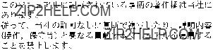
Connect the control terminal to the REMOTE3
Use the personal computer installing the terminal software as the control terminal of the router system.
Control terminal (IBM PC/AT compatibles)
n
REMOTE 3 connector of
When
The control terminal is not able to connect to the system which primary station is set to
In this manual, the monitor control line is called ???monitor
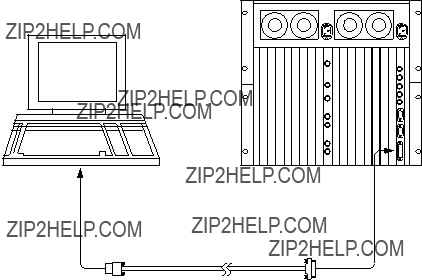
The input monitor and output monitor can be either used separately or combined. They can be also connected in cascade. As the crosspoint control of the monitor is performed separately from the standard
The configuration of the monitor

The following shows one way of connecting the monitor
(Max. 200 m)
(Inut signal)
Monitor
(Max. 200 m)
(M) (S) : M/S switch setting on the monitor Board.
: T Bridge (A)
: T Bridge (B)
: 75 ZTerminator
Section 2
Functions
1)The routing switcher is equipped with a system controller. It therefore does not require an additional controller for controlling the routing switchers.
2)By the cascade connection, up to 512 x512 crosspoints can be selected.
3)Up to 8 levels can be assigned.
4)Up to 254 units can be controlled in a system.
5)Each output signal can be protected so that they will not be switched by other control units. (Protect function)
6)Each input signal can be prohibited to be selected from all the control units. (Secret function) * 7) The inputs that can be selected for each output can be limited. (Crosspoint disable setting
function)
*8) Password function
*9) The either name of ???Type +Number??? or ???Description??? can be set for input/output connectors.
*10) A crosspoint matrix can be mapped on a virtual matrix. (Virtual mapping function)
*11) To each connector name, a different connector number can be assigned on each level.
(Free assignment function)
*12) Input and output signals can be monitored using the optional monitor board
*13) You can enable the system to automatically select the signal lines between two routing switchers. (Tie line function)
14)You can simultaneously switch several crosspoints. (Phantom function)
15)The control terminal connected to the primary station will display the system status informations and error messages.
16)When
17)
*:
The following outlines each function. (For details of how to set them, refer to the Section 5 ???System Settings???.)
The Sony digital routing switcher incorporates a system controller and therefore does not require a separate external controller. When several routing switchers are connected to the
By the cascade connection, input and output signals can be expanded to form a
Maximum matrix sizes depend on the kind of switchers.
.
.
.
.
.
.
n
The router system has the capability to control the different types of signal at the same time. This is enabled by the level setting.
The router system can handle the signals such as video, audio, timecode and the
In the router system, the different numbers are given to the input and output signals of the respective layers that enable switching of various signals at the different levels simultaneously.
Example: Video can be set to level 1, audio to level 2, etc.
Up to eight levels can be set for one system.
The levels are set in the menu item [E : SET LEVEL TABLE].
Up to 128 remote control units and switchers can be connected to one
Function which protects the crosspoint set so that it cannot be released using other remote control units. While the protect function is on, the destination of the crosspoint to be protected will be fixed. Once the protect is set, it will not be released by any command, except those from the control terminal and the control unit used to set it. The protect function can be set and released freely from the control terminal connected to the primary station.
The control terminal also has a password function which allows only certain users to operate the system. The protect function can be set in the menu item [C: SET DESTINATION NAME].
Function which ???hides??? certain sources from all control units to protect the crosspoint set so that it cannot be switched.
Unlike the protect function that limits the destinations, the secret function limits the sources to protect them from being selected by other control units.
The secret function can be set in the menu item [D: SET SOURCE NAME].
Function that limits the sources that can be selected for each destination. It can also be used to fix the area of crosspoints selected so that only certain sources can be selected for certain destinations. This function can be only used when a
This function can be set in the menu item [M: SET INHIBIT TABLE].
The control terminal can set all configuration items of the routing switcher system. It therefore has a password function which allows only certain users to operate it. The password can be set in the menu item [P: CHANGE PASSWORD].

The following names can be used for the input/output connectors of the routing switcher.
1.???Type+Number??? name
2.???Description??? name
There are altogether three kinds of numbers that can be set as input/output numbers. These are ???physical number???, ???connector number???, and ???virtual number???.
The physical number and connector number are the number of connectors attached to the switcher. For a
The virtual number is the numbers assigned when switchers are mapped on a virtual matrix with 512 inputs and 512 outputs. The numbers will not duplicate even if several switchers are mapped on the virtual matrix. Unless otherwise noted, the input/output number in this manual means the virtual number.
Virtual Matrix

The name ???Type + Num??? consists of four alphabets and three numbers. It is assigned to the virtual number. Sixteen kinds of letters can be set for the ???Type??? part. Number 1 to 999 can be used for the ???Num??? part.
Examples: CAM 234, VTR 145
The name ???Description??? consists of any 16 characters and is assigned to the virtual number, e.g. ???Tokyo??? and ???Market???. Up to 1024 kinds of names can be registered. The 160 kinds of them are transmitted to the remote control unit in order to set buttons and for displaying. The 160 names can be registered as one group. Data of 8 groups can be registered at the primary station. The data of remote control unit can be replaced by a group and the different data groups can be used for each remote control unit
Primary station
8 groups
Remote control unit
No. 1
No. 2
No. 3
No. 4
No. 8
1group : 160 names
No. 2 group
No. 2 group
No. 4 group
1 group for each unit
Description Name
The name ???Description??? can be selected the ???DESCRIP. NAME??? in the menu item [J: NAME STYLE] when a
After the selection, set the description name in the menu item [C : SET DESTINATION NAME] or [D :
SET SOURCE NAME].

Several routing switchers can be mapped on a virtual matrix with 512 inputs and 512 outputs in router system. The matrix of one switcher can be also divided into several virtual levels and mapped.
For example, a switcher handling the 4:2:2 video signal and a switcher handling the 4 fsc video signal can be mapped on the same level. By connecting them using a 4:2:2/4 fsc converter, the tie line control can be performed (refer to Section
In the figure below, the 12 x12 area where the level 2 and level 3 is overlapping is set to the 4
Mapping to

 :
:

 :
:
It is called ???Virtual mapping??? that you assign crosspoints using the virtual matrices and virtual levels in this way.
This virtual mapping function can be set in the menu item [L: SET PHYSICAL ASSIGNMENT] when a
n
When the matrix of a

While the same input/output number can be assigned, through levels 1 to 8, for each input/output name, different physical number can also be assigned on each level for an input/output name.
The following figure shows the case that
Similarly, to destination OUT004, physical number 32 can be assigned on level 1, physical number 32 on level 2, and physical number 4 on level 3.
This free assignment function can be set in the menu item [L: SET PHYSICAL ASSIGNMENT] when a

If a
By connecting the monitor signals of several switchers in cascade form, all input and output signals can be observed on one monitor.
The crosspoints of monitor signals are controlled by the monitor
The primary station on the monitor
For example, switchers
1
 Input Monitor (Separate connection)
m
1.For
However, for the monitor
2.
75 ZTerminate 
If the primary station is a
For example, if both a 4:2:2 video switcher and a 4 fsc video switcher have 32 sources and destinations, the converters can be shared using the tie line function and all sources and destinations can be handled with the minimum number of converters.
Net group
Converter
Routing Switcher
(4 : 2 : 2)
Net group
Routing Switcher
(4 fsc)
Destination group
Setting Procedure of the Tie Line
1.Set four input/output for each source/destination*1 group.
2.Set the four cables connecting the switchers for each net groups such as ???OUT ***_IN ***???.
3.Set the path from the source group to the destination (the path consists of the selected group names)
*1 : Source means the input signal. Destination means the output signal.
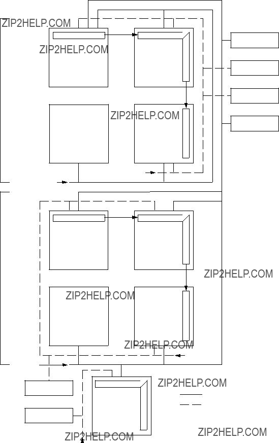
Operation example:
1.IN023 and OUT027 are selected from the remote control unit.
2.The CPU of the primary station detects IN023 from the source group. In the example below, the corresponding group is S002.
3.Like for IN023, the CPU also detects OUT027. The corresponding group is D002.
4.The CPU of a primary station detects the path which has the S002 and D002 groups. In the following example, the corresponding path is ???3:
5.As N004 will be detected as the net group to be used, the CPU selects a usable element (not protect-
ed) from the four
In the following example, if
Several crosspoints can be switched simultaneously with just one push of a button of the remote control unit. This is called the phantom function.
The phantom function is set using the control terminal connected to the primary station. The crosspoints are switched by the remote control unit.
The group of crosspoints switched together is called the phantom group. Each remote control unit stores the data of 57 crosspoints as the phantom group. In addition to the phantom function, in
The global phantom function is available if a
n
The
Refer to the operation manual supplied with equipment for more details.
The routing switcher performed
OPresence of board and its sort
OVersion of ROM on the control board
OPresence of backup power supply unit/backup CPU board
ODetection of fan rotation
ODisplay of reference signal
ODisplay of errors as follows
. Faulty crosspoint (hardware)
. Display of high temperature
. Display of
. Display of required secondary station???s disconnection or fault
. Display of backup unit (control board or power supply unit)???s fault/recovery.

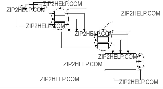
One of an application of Router is to expand number of Source inputs for
Route function is to display a source input chasing from a last program out even performing 4 times Re- entry function with
To activate the route function, set the destination of switcher A, destination and source of switcher B, and level. In case of the figure below, set ???OUT1 : OUT2 < IN5.???
When you use the route function, switching is possible with simple setting. For example if you select a source (IN1) for a destination (OUT1) on switcher A , the crosspoint on switcher B
On the other hand, when you select a source (IN1) for a destination (OUT2) on switcher A, you have to set a phantom, IN1 : OUT1 < IN1 previously. Then
If you define a certain number of outputs, you can vary a number of inputs which would not be capable with the older panel.
This is applicable with

Section 3
Control Terminal
Load Windows 3.1 to an IBM PC/AT compatible machine (CPU: 80486 or a faster and more powerful
When using personal computers, codes F1 to F5 must be set to the Windows screen.
It is possible to select codes F1 to F5 by using the cursor keys or using the [Ctrl] _[Alt] _[F||]* key combination.
Connect the personal computer to the primary routing switcher (REMOTE 3) using the
Symbols Used in This Manual
The symbols used for the control terminal keys in this manual are as follows.
(1)All keys are enclosed in boxes. (Ex. [Ctrl], [Return])
(2)The numerical keys in the text mean keys [0] to [9].
(3)The alphabet keys in the text mean keys [A] to [Z].
(4)The cursor key in the text mean the [(], [)], [&], and [*] keys.
(5)When two keys are to be pressed together, they are joined by the ??? _???. (Ex. [Ctrl] _[X])
Functions of Keys Used for Setting
Character key : Insert the character pressed where the cursor is.
[*]: Move the cursor to the right one space.
[&]: Move the cursor to the left one space.

The control terminal display consists of the following three types of screen.
. System status screen : It displays messages while the router system is operating.
. Menu screen : It displays the menu for setting the router system.
. Setting screen : It displays the setting items of each menu.
System Status Screen
[Ctrl] - [X] [Ctrl] - [X]
Menu Screen
*1 [Ctrl] - [E]
Setting Screen
Setting of the primary station
Menu Screen
*1 [Ctrl] - [E]
Setting Screen
Setting of the secondary station on monitor
Setting Screen
Setting of the primary station on monitor
*1 : The menu items can be selected in the following two ways.
1.Select the desirable menu item using the cursor keys, and press [Enter].
2.Press the alphabet key allocated to each menu item.
*2 : To move from the menu screen of the primary station to that of the secondary station, execute the menu item [R: CALL SECONDARY STATION] of the primary station.
*3 : To move onto the menu of the primary station on the monitor
n
Monitor function is able to work by

When the primary station is turned ON, the results of the
If the result of the
STARTED???
System Status Screen
When a message is output to the
???
Messages of the System Status
If some error or event happens while you open a Menu Screen or a Setting Screen, then the message will be displayed when you open the system status screen.
The display will change to the menu screen when [Ctrl] _[X] is pressed.
To return to the system status screen, press [Ctrl] _[X] again.
n
When [Ctrl] _[X] is pressed, the menu screen will be opened.
At this time, if the password is required, input the password.

The menu screen shows all menu items for system setting in the table data of the primary station.
By selecting the items on the menu screen using the following procedure, the screen will show the setting screen.
n
Compared with the system status screen, router system operations take more time, when the menu screen or the setting screen is open. Therefore, please return to the system status screen after system setting.
The following are two methods of selecting the menu items.
1.Use the cursor keys to select the desired menu item, and press [Enter]. (Some models have no this function. In this case, perform step 2. to select.)
2.Press the alphabet key assigned to each menu item.
The screen will return to the system status screen when [Ctrl] _[X] pressed.
Primary station menu screen of
Menu Screen of the Primary Station (Ex.
n
. Menu screen of
. Menu screen of
Station address
Menu item


To call the menu screen of the secondary station, select menu item [R: CALL SECONDARY STATION] in the primary station menu and input the secondary station number.
To set the secondary station function of the routing switcher used as the primary station, input ???1??? as the secondary station number.
The screen will return to the menu screen of the primary station when [Ctrl] _[D] is pressed.
n
When the secondary station menu is called, the color function will become ineffective, even if [S: SE- LECT INDICATION COLOR] has been selected to ???ON???.
(1) Routing switcher
1
Menu Screen of the Secondary Station (Ex.
2
U:SELECT REMOTE PROTOCOL???
??????
Menu Screen of the Secondary Station (Ex.

3
SONY ROUTING SYSTEM SETUP MENU???
Menu Screen of the Secondary Station (Ex.
n
4
MAINTENANCE COMMAND???
???
Z: SWITCHING FIELD???
???
Menu Screen of the Secondary Station (Ex.
5
Menu Screen of the Secondary Station (Ex.
(2)Remote control unit
1
???H: SET PHANTOM TABLE???
???N: SET PANEL TABLE???
???O: SET AVAILABLE DESTINATION???
???L: COPY TABLE DATA???
???
??? S: DISPLAY DESCRIPTION NAME???
???
Menu Screen of the Remote Control Unit (Ex.
2
???H: SET PHANTOM TABLE???
???N: SET PANEL TABLE???
??????
???O: SET AVAILABLE DESTINATION???
???L: COPY TABLE DATA???
???
???Z: SET PANEL STATUS???
???S: DISPLAY DESCRIPTION NAME???
Menu Screen of the Remote Control Unit (Ex.

3
???H: SET PHANTOM TABLE???
???N: SET PANEL TABLE???
??????
???O: SET AVAILABLE SOURCE/DESTINATION???
???R: SET ROUTE???
???
???L: COPY TABLE DATA???
???Z: SET PANEL STATUS???
???S: DISPLAY DESCRIPTION NAME???
Menu Screen of the Remote Control Unit (Ex.
n
4
???H: SET PHANTOM TABLE???
???N: SET PANEL TABLE???
???O: SET AVAILABLE SOURCE/DESTINATION???
???R: SET ROUTE???
???
???L: COPY TABLE DATA???
???Z: SET PANEL STATUS???
???Y: SET DISPLAY MODES???
???S: DISPLAY DESCRIPTION NAME???
Menu Screen of the Remote Control Unit (Ex.

To call the menu screen of the primary station on the monitor
Next, select menu item [M: SET MONITOR FUNCTION].
n
If a switcher except the primary station on the monitor
??? F: SET SCTIVE UNIT NUMBER???
???
??? M: SELECT MONITOR FUNCTION ( COMBINED )???
???
???
??? R: CALL SECONDARY STATION
Menu Screen of the Primary Station on Monitor
To call the menu screen of the secondary station on the monitor
Select menu item [R: CALL SECONDARY STATION] and input the station number.
(1)Routing switcher
1
SET MONITOR FUNCTION
???
???MODIFICATION COMMAND???
???
??? M: SET AVAILABLE MONITOR LINE INPUT=( ENABLE )OUTPUT=( ENABLE )???
???
???
???
???
???
Menu Screen of the Secondary Station on Monitor

(2)Remote control unit
1
???
???
???
Menu Screen of the Secondary Station on Monitor
2
???N: SET PANEL TABLE???
???L: COPY TABLE DATA???
???
???
??? Z: SET PANEL STATUS???
???
??? S: DISPLAY DESCRIPTION NAME???
???
Menu Screen of the Secondary Station on Monitor
Set the items in the menu in the setting screen.
To call the setting screen, select the menu item with the cursor key or input it using the alphabet key, and press [Enter].
(The same procedure for calling the setting screen is applied to both the primary station menu and secondary station menu.)
The screen returns to the menu screen when [Ctrl] _[E] is pressed at each menu item.
Then if [Ctrl] _[X] is pressed, the screen will return to the system status screen.
n
The setting screen of menu items ???C???, ???D???, ???E???, ???H???, ???L???, ???M???, ???N???, ???O???, and ???Q??? may differ according to the source/destination name mode set at menu item ???J???.
For the ???Type +Num??? mode:
. The name of the destination or source will be displayed in the form of type name and number.
.To set or change the name, select any name from the list displayed at the bottom of the screen and then input it using the numerical keys.
For the ???DESCRIP.NAME??? mode:
. The name of the destination or source will be displayed in the form of the Description.
. To set or change the name, directly input it using the alphabet or numerical keys.
Unless otherwise noted, the setting screen used in this manual are that of the ???Type +Num??? mode.
Section 4
Setup Procedure
This setup procedure is written for the setup operator to understand the setup procedure, and more importantly, the philosophy behind the setup. Time spent now, before actually sitting down at the Setup Terminal will greatly enhance the flexibility of your router system (routing switcher system). If your system is only comprised of
A router system with different types of routing switchers should usually be thought of as a 3 dimensional object. We will see in this procedure that in a few cases the old 2 dimensional model of a
Regarding detailed setup information, refer to the menus explanation in the Installation manuals chapter on setup.
What we will do in this procedure is to:
1.Identify all in/out signals, and segregate them into 16 types of sources and destinations.
2.Assign virtual inputs, and outputs a ???Type +number??? name. (numbers start at 001 and go to 512 for both source, and destinations)
3.Assign each output ???Type +number??? name to one or more levels.
4.Assign each ???Type +number??? name to an actual physical in/out location.
5.Assign any needed phantoms (also known as ???salvos???).
6.Decide which control units can be active on the
7.Decide which inputs won???t be available at selected outputs.
8.Setup any ???tie lines??? needed.
9.Assign second naming convention (if desired).
10.Setup individual control units on the
Regarding steps 1 through 4, these are important steps (with step 2 being the longest, and most critical). As an introductory explanation, it should be clear that we humans like to deal in names, while the
For details of setting information, refer to the Section 5.

The control area of each switcher when used as the primary station is as follows.
Example :
. Be sure to set a station number for each routing switcher and remote control unit installed. Refer to the manuals of each unit for how to set the station number.
. In this manual, the input signal is called source, and the output signal destination.
.When using two or more
1. Set a primary station
Station ID automatically will equal one. n
Set only one primary station.
If more than two are set as the primary, they will not work correctly.
2. Connect PC
Connect a IBM compatible PC with
Run terminal emulation software and communicate at 9600 bps*3.
The Terminal program associated with Windows 3.1 allows the mapping of control strings to virtual function keys in the terminal program. Therefore, if your are using Windows 3.1 you can use it???s Termi- nal program. Windows 95, and Windows NT have terminal emulation programs which do not have this feature. If you are using a PC with Windows 95 or Windows NT, you must use a third party terminal emulation program that allows control strings to be mapped to keys on the keyboard (usually the F1 through F12 function keys).
3. Turn on the power
Turn on the power of all equipment connecting on the
Operation of the routing switcher may be unstable just after the power is turned on. Wait about one minute of
*1 : Set the P/S switch of the
*2 : Use the
*3 : Data transfer speed of

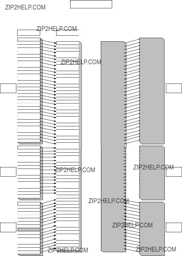
1. Identify all in/out signals, and segregate them into 16 types of sources and destinations
(1) Make IN/OUT list of each routing switcher
Make input/output list of each routing switcher referring to installation, or wiring diagram or other documentation showing router interconnection. Figure 1 shows an example of a 3 router system. It is composed of an SDI, AES/EBU, and a Analog routing switcher.
At this time consider the mnemonics that can be assigned to each of the inputs or outputs.
The DVS series routing switcher can accept up to 16 unique, 4 letter (maximum)
n
Type Name = Mnemonics
Each
The same name (such as VTR001) can be assigned to a input, and to an output of the routing switcher. But, a unique name can only be used once per input, and output. It is important that you consider careful- ly your naming convention now, as it will be carried throughout the rest of the setup, and will be the name displayed on control panels, and other displays. Actual Source and Destination descriptive names are decided later.
n
There is a second naming convention that can be used in place of the ???Type +number??? format.
But it is necessary to first enter names under the just mentioned format, and add the second set of names later (they do not erase the ???Type + number??? set). The second approach is called Descriptive Names. It is explained in step 9.
Example :
VIDEO ROUTER SOURCE
VIDEO ROUTER DESTINATION
Fig. 1
Name Types
(2) Assign Name Types (Menu Item [B])
Now select, and enter your 16 source and destination name
Once again, up to 16 type names used for source/destination name are decided using 4 letters (except ???;???). Set using the menu item [B : SET SOURCE/DESTINATION TYPE].
Example : CAM, VTR, CG, DVE, MON, PGM, BLK, DAT, STL, TONE, CD, ...
If a consistent display format is desired, all name types should be the same length.
2. Source/Destination names (Menu Items [C] & [D])
At this point another very important decision must be made as to how your router system is organized, programmed, and ultimately able to be used. You should take some time at this point to read, and totally understand the implications of what this step in the setup means for future routing switcher setup, opera- tion, and flexibility. How you approach this step will greatly determine the flexibility your system will afford in control panel operation, and ease of system modification.
Many router systems are not only comprised of a SDI routing switcher
These additional types of routing switchers can be thought of as ???assets??? (secondary stations) to be managed by the primary. These ???assets??? are additional crosspoints for switching analog video, or audio, time code, etc. Your method for controlling these additional crosspoints are generally though control panels attached to the
There are two general approaches that can be taken in ???mapping??? crosspoints.
Although either approach can be mutually exclusive of the other, generally a mixture of the two are used.
The first approach is called ???level mapping???. There are sources where the digital (video), and analog audio or video routing switchers should naturally follow one another (VTR???s for instance). With sources that should follow, you can use ???level mapping???, with the SDI routing switcher on level 1, and the audio analog routing switcher on level 2, etc..
Looking at figure 1, VTR001 could have:
its SDI input connected to
and its AES/EBU audio input connected to
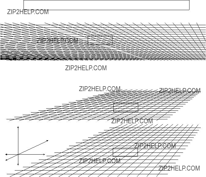
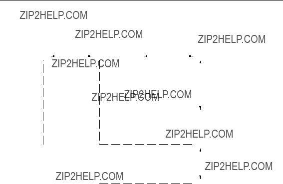
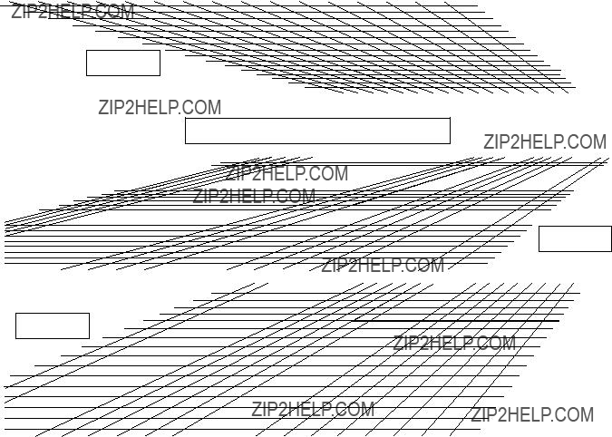
Figure 2 shows that no two levels need to occupy the same size space in the X, and Y directions. As our example in figure 1 demonstrates, level 1 could be 32 by 32 in 2 dimensional X, Y space, while levels 2, and 3 are only 16 by 16.
Actually each level could occupy different size X, and Y space. Finally, it should be clear that Z ???depth???, is three in our case since we have 3 levels.
Levels Can occupy different size 2 dimensional space
Level 1
Level 2
Z
Fig. 2
Going back to the VTR 1 example, each of the 3 routing switcher outputs (SDI, AES/EBU, and analog audio) could be assigned to a different level, under the VTR001 label.
Whenever destination VTR001 was selected all 3 crosspoints in the 3 different routing switchers would switch together. This approach is often the simpler approach to implement, and understand, but it can limit future flexibility in operation, as we will see.
Level Mapping
Fig. 3
With this approach, you need the control terminal connected to the primary routing switcher, or a control panel that allows access to individual ???levels???, like the
Figure 4 shows this approach.
Level Approach
Fig. 4
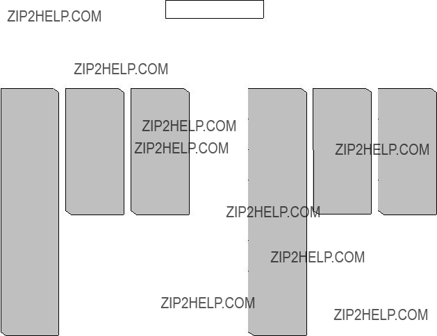
The second approach is ???virtual mapping???. There are sources that don???t logically follow one another, looking at figure 4, you can see that News 1, and DAT 2 on the source side, Satellite 1, and DAT 1 on the destination side are just 2 of many that wouldn???t normally be switched together. In this case the approach shown in figure 5 could be used.
Virtual Approach
SDI
Routing
Switcher
AES/EBU
Routing
Switcher
Analog
Routing
Switcher
Physical Inputs
VTR 1
VTR 2
VTR 3
VTR 4
VTR 5
VTR 6
VTR 7
VTR 8
Studio A
News 1
Satelite 1
Satelite 2
Network 1
Network 2
Remote 1
Remote 2
Camera 1
Camera 2
Camera 3
Camera 4
Still Store 1
Still Store 2
Char Gen 1
Char Gen 2
Frame Sync 1
Frame Sync 2
Studio B
Patch
Patch
Patch
Patch
A/D #1
VTR 1
VTR 2
VTR 3
VTR 4
VTR 5
VTR 6
VTR 7
VTR 8
DAT 1
DAT 2
DAT 3
A/D #1
A/D #2
Mixer 1 PGM
Mixer 1 Aux
SDI Demux Out 

VTR 1
VTR 2
VTR 3
VTR 4
VTR 5
VTR 6
VTR 7
VTR 8
Mixer 2 PGM Out
News 1
Satelite 1
Satelite 2
Network 1
Network 2
Remote 1
Remote 2
SDI
Routing
Switcher
AES/EBU
Routing
Switcher
Analog
Routing
Switcher
A pure virtual mapping approach would keep all destinations on 1 virtual level (although physically there is still 3 levels) as figure 5 shows.
Example : Destinations
. Satellite 1 connected to SDI routing switcher OUT 9 (SDI routing switcher given label destinations
. DAT 1 connected to AES/EBU routing switcher OUT 9 (AES/EBU routing switcher given label destinations
.Satellite 1 connected to Analog Audio OUT 9
(Analog audio routing switcher given label destinations
Analog Audio Satellite 1 (Sat003) ?????????????????? virtual level 1 out label 57
If DAT001 destination is changed on a control panel only output label 41 (AES OUT 9) changes. Good in situations where few signals logically follow from one level to the next (DAT???s and cameras, Mics and CG???s, Audio Mixers and Still Stores, etc.). With this approach any sources/ destinations that should follow across multiple routing switchers would require phantoms (covered later) to implement multiple crosspoints switched.
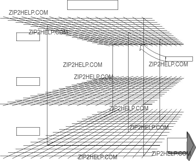
A combination of virtual, and level mapping combines both approaches as shown in figure 6.
Level 1
Virtural and Level Mapping
Level 2
Level 3
Fig. 6
With this approach sources, and destinations like the VTR???s would be level mapped together so that all 3 routing switchers switch at the same time under the VTR001, VTR002, etc. label.
But in the case of output 11, of each of the 3 routing switchers, the 1, and 3 levels (SDI, and analog audio respectively) would be level mapped and switched together (REM001) while output 11 of level 2, which is DAT003 would be virtually mapped off away from the other 2, so that it could be easily switched on it???s own.
Example : Level 1, & level 3 outputs 11 are tied together under the REM001 label Level 2, mapped out from under level 1 output 11 under the DAT003 label
If DAT003 destination is changed on a control panel only level 2 output 11 crosspoint on the AES/EBU routing switcher changes. If REM001 destination is changed both levels 1, and 3 change. This approach is good for a mixture of signals where routing levels follow in some instances, but not always.
n
Sources/Destinations where all associated crosspoints on all levels should follow would be mapped only by levels. Sources/Destinations which shouldn???t follow would be mapped virtually.
Again, a pure level mapping approach is where all physical inputs 1, 2, etc are tied together on different levels (see figure 4).
A pure level mapping approach is usually the worst approach. In our example here DAT 3, which is on output 11 of the AES/EBU routing switcher appears as REM001 on all control, and display, panels if the level only approach is taken.
Using the virtual/level mixture approach you will get separate video, and audio tallies (control panel push button lit). As an example, (see figures 7, and 8) if you use the 2 entries from the virtual example above and assign both of them to the same control panel (on different buttons), if REM001 is selected with it???s button, the REM 1 button is tallied green. Now if DAT001 is selected with it???s button, the DAT 3 button is tallied amber, while the REM001 button remains green. The DAT001 button will stay tallied when other sources are selected as long as those sources are assigned to level 1, or 3, and not level 2.
When a button is selected with levels 1, and 2 active the DAT001 audio source button is turned off, as the primary switches both levels of crosspoints.
Conversely, if REM 1 (green tally) is selected, and DAT 3 (amber tally) is selected, and another level 2 only source is selected, say DAT 2, the DAT 3 amber tally will extinguish, and the DAT 2 button will now be tallied amber. The REM 1 green tally will remain on, unchanged.
A final note on figure 7.
This is a two dimensional drawing depicting a 3 dimensional object. Therefore the top half of the draw- ing represents the X axis, the bottom half the Y axis, and from left to right the Z axis.

DAT 1
DAT 2
Level 1 (SDI)DAT 3
D/A #1
D/A #2
Mixer 1 In 1
Mixer 1 In 2
SDI Mux In
A/D #1
A/D #2
Fig. 7
VTR 001
VTR 002
VTR 003
VTR 004
VTR 005
VTR 006
VTR 007
VTR 008
STU 111
NEWS 001
SAT 001
SAT 002
NET 101
NET 102
REM 101
REM 102
CAM 001
CAM 002
CAM 003
CAM 004
SS 001
SS 002
CG 001
CG 002
FS 001
FS 002
STU 121
PTCH 001
PTCH 002
PTCH 003
PTCH 004
DIG 101
DAT 001
DAT 002
DAT 003
DIG 201
DIG 202
MIX 201
MIX 202
DIG 203
VTR 001
VTR 002
VTR 003
VTR 004
VTR 005
VTR 006
VTR 007
VTR 008
SAT 001
SAT 002
REM 001
NET 001
NEWS 001
NEWS 002
CG 001
CG 002
CAM 001
CAM 002
CAM 003
CAM 004
STU 111
STU 112
MON 111
MON 112
SS 001
SS 002
NEWS103
STU 121
STU 122
FS 001
FS 002
DIG 101
DAT 001
DAT 002
DAT 003
DIG 201
DIG 202
MIX 201
MIX 202
DIG 203
DIG 301
DIG 302

Now select suitable names for sources/destinations using Type name, and number and enter them in the IN/OUT list of each routing switcher (menu item [C]).
Remember that you have to attention to the ins, and outs of routing switchers on all levels when you build this list.
Example :
VIDEO ROUTER SOURCE
VIDEO ROUTER DESTINATION
n
After destination (crosspoint/output) names have been set, the Protect mode may be implemented for that destination (crosspoint can???t select another input).
After source (inputs) names have been set, the Secret mode may be implemented for the source (input not selectable by control panels).
Both of these modes can be only be set, or disabled via the terminal.
3. Set Level Table (Menu Item [E])
This is the step where you assign what levels you want each name or label to be assigned to. You also assign the names of the various levels (here SDI, AES, and AUD are used).
The information entered here was derived from figure 7.
n
Delete levels not used so that these levels do not show on panels, or displays that use levels. The deleted levels are displays as ??? . . . .???.
4. Physical Assignment (Menu Item [L])
Now we actually associate the labels or names to a physical routing switcher input or output. Assign the physical source/destination number and the physical level to the virtual source/destination name and the virtual levels using the menu item [L : SET PHYSICAL ASSIGNMENT].
Again refer to figure 7.
m
1.Create a similar table for the destination side (use F5 on the terminal setup menu [L] screen to toggle between source/destination)
2.To delete an entry in menu item [L], press the [Ctrl] _[P] .
This step can be confusing because you associate the input labels with physical routing switcher inputs, along with output labels with physical outputs. You need to tell the primary which physical X row of crosspoints feeding an output belong with each output name or label, along with which physical Y column of crosspoints fed by an input belong with each input name or label. To visualize, look at figures 2, 3, or 4.
n
When
When number of items to set is smaller than number of items to clear, the procedure of clearing all items once and setting all items from the very beginning is more efficient.
Additionally, an individual routing switcher can be divided in 2, or more virtual routing switchers. This means that one level can be made to look like 2, or more levels. In our example our 3 level routing switcher could have the AES/EBU routing switcher split into 2 virtual levels.
Our 3 routing switcher system would now have 4 levels.
Why would you want to do this? If you have an AES/EBU routing switcher that handles 2 AES/EBU audio programs per digital signal, but your plant uses 4 channels, this means it takes 2 AES/EBU signals for 4 channels. As before, there would be many times that you would want to switch these together, and many times you would not. Also, in many cases you would have only one AES/EBU audio frame. Therefore, AES/EBU Channels 1/2 would arrive at one input while AES/EBU Channels 3/4 would arrive at another input of the same routing switcher. You could use phantoms (step 8) to link these inputs together when desired, or you could create 2 distinct levels for one physical routing switcher frame using menu item [L]. One level could be known as A1/2, and the second A3/4. Entries to do this might look like the examples below.
This is a good place to point out that physical crosspoint usage does not have to be in numerical order.
5. Phantoms (Menu Item [H])
Now we will create any necessary phantoms. First we must define the phantom globally, and then allow it???s usage by individual control panels. A phantom allows you to have a number of outputs select new inputs all at once.
An instance of a global in our example would be the selection of input SAT001 (SDI level and the Analog audio level) to output VTR001, and DIG201 (AES level) to output VTR001. We could call this phantom SAT999. It???s entry as a global phantom would look like this
(1) In the top of menu item [H] we would assign our name to a numbered label:
(2) Once the name is assigned we are in an edit menu, where we actually assign inputs to outputs:
Up to 4096 crosspoint changes can be stored among the Global phantoms.
For a control panel to be able to use a global phantom, that secondary station must be called (menu item [R]), and the name of the global phantom loaded into it???s phantom table. Up to 57 crosspoint *1 changes can be stored among each secondary stations (control panels) phantoms.
Local phantoms may be created in each control panel. Below is an example of a local phantom residing in a control panels phantom table :
We can see here that our global phantom SAT999 is the first entree. The 0001 that trails SAT999 means that this global phantom is the first entry in our global phantom table (menu item [H]). Next we can see that locally (only at this control panel) we have defined a local phantom called CAM999. It selects the Studio A (STU111) input, and sends it to our 4 camera return outputs (CAM001, etc.) whenever it is selected. The ??? _1??? means that level 1 (SDI) is switched.
SAT999, and CAM999 could be assigned to buttons on this control panel just like any other source, or destination name could be.
*1 : Up to 64 crosspoint changes can be stored in

6. Decide Remote Control Units Can Be Active on the
(1) Available Stations (Menu Item [F])
Make secondary stations available by setting ???E??? on the menu item [F : SET ACTIVE UNIT NUMBER. The stations that are enabled will be polled by the primary, for panel activity, and status updates.
ENABLE ACTIVE UNIT FOR STATION NUMBER???
???
1 2 3 4 5 6 7 8 9 10 11 12 13 14 15 16 17 18 19 20???
n
Before this setting each secondary station has to have its ID set using the
For your reference,
(2) Detection of Stations (Menu Item [Z])
If you set ??????? to a ID location in the menu item [Z], the primary station will display the corresponding model code of that location and display a warning if communication is interrupted.
m
1.This menu is used with
2.
3.Once a ??????? is entered you must exit, and

7. Inhibit Crosspoint Table (Menu Item [M])
Set invalid crosspoint table for the specified crosspoints that will not be allowed to be selected by various outputs INHIBIT TABLE on the primary station.
On the table ???X??? means valid crosspoint, and ??? _??? means invalid crosspoint.
Be careful that destination cannot select a source which makes up a loop in which the destination be- comes the signal generating source in order to avoid potential operational mistake.
In the example here the output VTR001 can not select input 1 (VTR001), etc.
8. Tie Line Management (Menu Items [N] & [O])
This comes into play mainly if you have different types of serial digital data. Such as having both 4fsc, and 4:2:2 signal streams in the same routing switcher level. By using the menu item [R : CALL SEC- ONDARY STATION] you can have the primary call itself, and configure the primary to handle either standard in groups of 8 inputs, and outputs. The same can be done be calling secondary stations on the same level.
If you have both types of signal you probably need to convert from one standard to the other often. To prevent the need to have many converters, you can set up the system recursively
4:2:2 Inputs
Instead of one large routing switcher, there are often 2 separate routing switchers. One handling 4:2:2, and the other 4fsc. The output of the 4:2:2 would cascade through the 4:2:2 to 4fsc converters, and on to the inputs of the 4fsc routing switcher. The opposite configuration would be set up for going from 4fsc to 4:2:2.
What is done here is that groups of inputs are combined in a Source Name group, along with groups of outputs known as Destination Name groups. Net (Path) Groups are then created, each one being a list of routing switcher outs to routing switcher in???s to be used.
When a input in a source group is selected, or an output in a destination group, the routing switcher looks at successive paths (their order as entered in each path group) until it finds an unused one.
n
Each Source, Destination, and Net group can have up to 4 entries in it.
There can be a total of 20 Source, and 20 Destination groups.
There can be up to 40 Net groups.
Each Source and Destination group are tied together by 1 Net group.
Up to 3 routing switchers, or 2 recursive paths into 1 routing switcher can be supported.

9. Description Name (Menu Item [J])
In addition to Type +Number names, letter names (16 letters can be displayed on the
This is called a ???Description name???.
To set to Description names mode, select DESCRIP.NAME using the menu item [J : NAME STYLE]. Everytime [J] is selected in the System Setup Menu the name mode toggles between Type +Number, and Description name modes.
After [J] has been selected for the first time, go back to menu items [C] and [D] and enter the descriptive names, if desired.
n
The description name can be used repeatedly for the sources and destinations.
10. Control Panel Setup (Menu Item [R])
Each individual control panel is contacted, and programmed by selecting [R] in the setup menu, and then by entering the
Once the menu page of the control panel is displayed select the menu item [Z : SET PANEL STATUS]. From this
Next select the menu item [N : SET PANEL TABLE]. Using this
If the panel being programmed is a
In
[Ctrl] _[F].
When there are several control panels with similar, or identical setups you can use the menu item [L : COPY TABLE DATA] to copy setup data from one control panel to another.
n
Use menu item [L : COPY TABLE DATA] from the panel you will copy data to!
Once you have copied the setup to a new panel you can edit that panels settings through the

P:CHANGE PASSWORD
T:SET CLOCK
V:SELECT WARNING DISPLAY
B: SET SOURCE/DEST TYPE
J: NAME STYLE
C:SET DESTINATION NAME
D:SET SOURCE NAME
E:SET LEVEL TABLE
F:SET ACTIVE UNIT NUMBER
L:SET PHYSICAL ASSIGNMENT
H:SET GLOBAL PHANTOM
M:SET INHIBIT TABLE
N:SET DESCRIPTION NAME GROUP
O:SET TIE LINES
R: CALL SECONDARY STATION
1.Set the switch
2.Select the menu item [R: CALL SECONDARY STATION] from the menu screen of primary station, and call
The following screen appears.
Model name Software version indication
(Example of
1 SOURCE LOCATION of equipment. Input range is set here.
2 DESTINATION LOCATION of equipment. Output range is set here. 3 LEVEL of equipment is set here.
4 The MATRIX switching timing is set here. (Select either ASYNC or FIELD.)
5The SDI format is set here. (Available in
(Select a type from three formats of 4: 2: 2, 4fsc NTSC or 4fsc PAL.)
3.Set the above described items from 1 to 5.
(1) Set the items from 1 to 3 as follows. Select an area to modify using the cursor key. Enter any
desired value using the numeric keys on the control terminal.
(2) Set the items 4 and 5 as follows. Select an area to modify using the cursor key, and press
[Enter].
Every pressing of [Enter] increments the preset values in order.
4.Press [Ctrl] _[D] to return to the menu screen of primary station from the setting screen.

Section 5
System Settings
A : DISPLAY CONTROL AREA
A : DISPLAY UNIT LOCATION
Purpose
The menu items [A : DISPLAY CONTROL AREA] and
[A : DISPLAY UNIT LOCATION] are used to check the source and destination area of the whole routing system to be controlled by the primary station.
Checking Procedure
1.Select menu item [A].
2.Control area is displayed as shown below. Press [Ctrl] _[E] to return to the menu screen.
The following table lists the control area and setting area for each model.
n
The control area of the menu item [A] means the control area of the whole routing system, and not the input/output area of the primary station.
To set the source/destination location of the primary station, call the secondary station menu screen by selecting menu item [R] and type the station number [1], and then select the menu item [A] of the secondary station.

This menu is used to set the type name of the source destination and global phantom table.
The menu makes the management of source/destination easier.
Setting Procedure
1.Select menu item [B].
2.Use the cursor or alphabet/numerical keys and select the codes for the type name to be registered from the sixteen character codes (0 to 9 and A to F) displayed on the screen.
3.When [Ctrl] _[P] is pressed, the setting of the type
name will be canceled, and ??? ?? ?? ?? ?? ??? will be displayed.
4.When [Enter] is pressed, the type name can be set. If [Enter] is pressed again before entering the type
name, the registration will be deleted and the cursor moves to the next position.
5.Use the alphabet and numerical keys to enter the type name (within four letters).
6.When [Enter] is pressed, the type name will be set
and the cursor moves to the next position.
If [Ctrl] _[F] is pressed before the setting, the original type name will be returned.
7.When [Ctrl] _[E] is pressed, the menu screen will be displayed.
???
Example of Setting Screen
This menu is used to set the destination name and protect function of each output.
A number between 001 to 999 and a type name set at the menu item [B : SET SOURCE/DEST TYPE] can be set to each destination. Description name can be set by chang- ing the name mode at the menu item [J : NAME STYLE]. For details of setting the name, refer to [J] in the menu. The protect function (to protect the output signal from being controlled from the remote control unit) prevents the source signal selected for the specified destination from being switched by other remote control units.
(During recording and ON AIR, interrupting operations can be prevented.)
Setting Procedure (Destination Name)
1.Select menu item [C].
2.Press the cursor keys or the function keys to select the destination number.
3.When [Ctrl] _[P] is pressed, the set destination name will be deleted and ??? ?? ?? ?? ?? ??? will be displayed.
4.When [Enter] is pressed, the destination name can be
typed.
If [Enter] is pressed again before entering a name, the registration will be deleted and the cursor moves to the next position.
5.Select the code assigned to each type name, and use the numerical keys to enter the destination name.
6.When [Enter] is pressed, the destination name will be
set and the cursor moves to the next position. If [Ctrl] _[F] is pressed before the setting, the
original destination name will be returned.
7.When [Ctrl] _[E] is pressed, the menu screen will be displayed.

n
1.The same destination name cannot be registered at more than two destinations. If this is done, an error message will be displayed at the bottom of the screen.
Example: ??? VTR001 is used already; Ignored???
 destination name
2.When the Description name mode is selected at menu item [J], both Description name and ???Type +number??? name will be displayed.
In this menu, Description name is used for setting.
Setting Procedure (Protect Function)
1.Select the destination name using the cursor, and then press [P]. ???P??? is displayed after the selected destina-
tion name and the protect function is set.
Protect function cannot be set for a number whose destination name has not been assigned.
2.To release the protect function, select the destination name and press [P] once again.
m
1.If a destination name is reversed, it means the protect function is set with a control terminal and not with a remote control unit.
2.To change the protected destination name, release the protection first before beginning the modification process.
Example of Setting Screen
Operating Function Keys
[F1] : SEARCH (To move the cursor to the desired destination name)
1.When [F1] is pressed, ???Please Input DEST. NAME =??? will be displayed.
2.Input the destination name to be retrieved.
3.When [Enter] is pressed, the cursor will move to the desired destination name.
n
When menu item [J] is set to the Description name mode, [F1] (SEARCH) will have the following functions.
1.When [F1] is pressed, ???Please Input NAME =???will be displayed.
2.Enter the Description name (within seven characters) from the head.
3.When [Enter] is pressed, the Description name entered will be searched.
4.If the desired name does not exist in the screen, press [F1] again.
[F2] : JUMP (To move the cursor to the destination number)
1.When [F2] is pressed, ???Please Input DEST NUMBER =??? will be displayed.
2.Input the destination number to be retrieved.
3.When [Enter] is pressed, the cursor will move to the desired number.
[F3] : Pg Up
When [F3] is pressed, the screen will display the 16
lines previous to the 16 lines displayed currently. [F4] : Pg Dn
When [F4] is pressed, the screen will display the 16 lines next to the 16 lines displayed currently.

D : SET SOURCE NAME
Purpose
This menu is used to set the source name and secret function (inhibition of source selection with a remote control unit).
A number between 001 to 999 and a type name set at the menu item [B : SET SOURCE/DEST TYPE] can be set to each source name. Description name can be set by changing the name mode at menu item [J : NAME STYLE] in the menu. For details of setting the name, refer to [J] in the menu.
The secret function is necessary when a source signal should not be taken. When secret is set, remote control units cannot select the source signal.
Setting Procedure (Source Name)
1.Select menu item [D].
2.Press the cursor keys or the function keys, to select the source number.
3.When [Ctrl] _[P] is pressed, the source name will be deleted.
4.When [Enter] is pressed, the source name can be typed. If [Enter] is pressed before entering a name,
the registration will be deleted and the cursor moves to the next position.
5.Select the code assigned to each type name, and use the numerical keys to enter the source name.
6.When [Enter] is pressed, the source name will be set
and the cursor moves to the next position.
If [Ctrl] _[F] is pressed before the setting, the original source name will be returned.
7.When [Ctrl] _[E] is pressed, the menu screen will be displayed.
n
1.The same name cannot be given to assigned to two or more sources. If this is done, an error message will be displayed at the bottom of the screen.
Example: ??? VTR001 is used already; Ignored???
 source name
2.When the Description name is selected at menu item [J], the screen will display the Description name in addition to the ???Type +Number??? name.
In this menu, the Description name is used for settings.
Setting Procedure (Secret Function)
1.Select the source name using the cursor, and press [S]. ???S??? is displayed after the source name, and the secret
is set. Secret cannot be set for a number whose source name has not been assigned.
2.To release the secret function, select the source name and press [S] once again.
When the password is required, input the password and press [Enter]. The secret will be released.
n
For details on password settings, refer to the menu item [P
: CHANGE PASSWORD].
Example of Setting Screen

Operating Function Keys
[F1] : SEARCH (To move the cursor to the desired source name)
1.When [F1] is pressed, ???Please Input SOURCE NAME =??? will be displayed.
2.Input the source name to be retrieved.
3.When [Enter] is pressed, the cursor will move to the desired source name.
n
When menu item [J] is set to the Description name mode, [F1] (SEARCH) will have the following functions.
1.When [F1] is pressed, ???Please Input ****
NAME =??? will be displayed.
2.Enter the Description name (within seven characters) from the head.
3.When [Enter] is pressed, the Description name entered will be searched.
4.If the desired name does not exist in the screen, press [F1] again.
[F2] : JUMP (To move the cursor to the source number)
1.When [F2] is pressed, ???Please Input SOURCE NUMBER=??? will be displayed.
2.Input the source number to be retrieved.
3.When [Enter] is pressed, the cursor will move to the desired number.
[F3] : Pg Up
When [F3] is pressed, the screen will display the 16
lines previous to the 16 lines displayed currently. [F4] : Pg Dn
When [F4] is pressed, the screen will display the 16 lines next to the 16 lines displayed currently.

E : SET LEVEL TABLE
Purpose
This menu is used to assign the level name and the level to each destination name. Up to eight levels can be set.
In this menu, set only the necessary levels. If levels which have not actually been used are set, the response of the routing switcher system will become slower. Delete all levels not needed.
After setting this menu item, the selected levels can be checked by remote control unit.
Setting Procedure (Setting of Level Names)
1.Select menu item [E].
2.Press the cursor keys or the function keys to select the level number 1 to 8.
3.When [Enter] is pressed, the level name can be assigned.
4.Enter the level name using the alphabet and numerical keys (within four characters).
5.When [Enter] is pressed, the level name will be set. If [Ctrl] _[F] is pressed before the setting, the
original level name will be returned.
6.When [Ctrl] _[Z] is pressed, the level 1 to 8 will be assigned to all destination names.
7.When [Ctrl] _[E] is pressed, the menu screen will be returned.
Setting Procedure (Level Setting .Release)
1.Select menu item [E].
2.Use the cursor keys to select the destination level.
3.When [Enter] is pressed, the level name will be
deleted and displayed as ??? ?? ?? ?? ?? ??? and the level setting will be released.
4.You can search the level with the function keys.
Example of Setting Screen
Operating Function Keys
[F1] : SEARCH (To move the cursor to the desired destination name)
1.When [F1] is pressed, ???Please Input DEST NAME =??? will be displayed.
2.Input the destination name to be retrieved.
3.When [Enter] is pressed, the cursor will move to the desired destination name.
n
When menu item [J] is set to the Description name mode, [F1] (SEARCH) will have the following functions.
1.When [F1] is pressed, ???Please Input NAME =??? will be displayed.
2.Enter the Description name (within seven characters) from the head.
3.When [Enter] is pressed, the Description name entered will be searched.
4.If the desired name does not exist in the screen, press [F1] again.
[F2] : JUMP (To move the cursor to the number of the desired destination)
1.When [F2] is pressed, ???Please Input DEST NUMBER =???, will be displayed.
2.Input the destination number to be retrieved.
3.When [Enter] is pressed, the cursor will move to the desired destination number.
n
If the destination name is not set, the number of the destination will not be displayed.

F : SET ACTIVE UNIT NUMBER
Purpose
This menu is used to enable the units connected to the S- BUS data link to communicate.
Setting Procedure
1.Select menu item [F].
2.Press the cursor keys to select the secondary station whose communication will be valid.
3.When [Enter] is pressed, the setting displayed will change (???E??? ??? blank ??? ???E???). Only the secondary
stations displayed with ???E??? are valid. (???M??? indicates the primary station.)
4.When [Ctrl] _[E] is pressed, the menu screen will be displayed.
n
As the response will become slower if there are many secondary stations, make the secondary stations not connected invalid.
??? *??? indicates out of the control area.
ENABLE ACTIVE UNIT FOR STATION NUMBER
???
Example of Setting Screen
m
1.Station ID of the primary station is always regardless of the DIP switch setting on the CPU board.
2.Station ID of the secondary station is deter mined with the DIP switch setting. Do not assign the same number on two or more units as station ID on both standard
Number that can be registered as secondary station ID are 2 to 254.
G: UPDATE BACKUP CONTROLLER
Purpose
This menu is used to copy the table data stored in the main CPU board of the primary station to the backup CPU board.
This setting is valid only when the backup CPU board is installed in the primary station.
Setting Procedure
1.Select menu item [G]. The message ???This process requires about n minutes. Execute? (y/n)??? will be displayed at the bottom of the screen.
Ver. 2.00 : n=5
Ver. 1.00 : n=7
2.Table data copying is performed when [Y] is pressed. To cancel copying, press [N].
3.After copying, ???PROGRAM TABLE? (y/n)??? may be
displayed at the bottom of the screen. In this case, press [Y].
m
1.The ROM version of the main CPU board and that of the backup CPU board must be the same. If different versions are used, the unit may hang up due to copy- ing. Remove the backup CPU board when this occurs. The above occurs because a new table data can not be run on the old version software.
2.It takes about seven minutes to copy the table data. The copy makes other operations slow.
3.The table data of transcode from
4.When you copy the data of main CPU to backup CPU on the menu screen [G : UPDATE BACKUP CON-
TROLLER] of the primary station or a secondary station, you can abort the operation by pressing [Ctrl]
_[D].
However you should copy again for the data of the backup CPU is not correct if aborted. Even if you do not copy again, the data will be renewed in one hour approximately by the auto backup function.

H : SET GLOBAL PHANTOM
The phantom function switches several crosspoints together with one button pushing of a remote control unit. The crosspoints of different levels can be also switched with this function.
There are two kinds of phantoms such as local phantom and global phantom (refer to the menu item [H : SET PHANTOM TABLE] of secondary stations for local phantom).
In local phantom function, the phantom data is stored in a remote control unit, and the phantom name is assigned only on this remote control unit. In global phantom function, however, the phantom data is stored in the primary station, and it can be called by any remote control unit. The global phantom function can be set only when
The following describes how to set the global phantom data in the primary station. A maximum of 4095 cross- points can be registered.
Setting Procedure
1.Select menu item [H]. The global phantom list will be displayed.
2.Select any global phantom number with the cursor or function key and press [Enter]. The edit screen will
be displayed.
When [Ctrl] _[E] is pressed, the menu screen will be displayed.
Example of Global Phantom Screen
Operating Function Keys
(Global Phantom Display)
[F1] : SEARCH (To move the cursor to the desired global phantom name)
1.When [F1] is pressed, ???Please Input PHAN- TOM NAME =??? will be displayed.
2.Input the global phantom name to be retrieved.
3.When [Enter] is pressed, the cursor will move to the desired name.
[F2] : JUMP (To move the cursor to the desired global phantom number)
1.When [F2] is pressed, ???Please Input PHAN- TOM NAME =??? will be displayed.
2.Input the global phantom to be retrieved.
3.When [Enter] is pressed, the cursor will move to the desired number.
[F3] : Pg Up
When [F3] is pressed, the screen will display the 16
lines previous to the 16 lines displayed currently. [F4] : Pg Dn
When [F4] is pressed, the screen will display the 16 lines next to the 16 lines displayed currently.
3.As the cursor is placed where the name is typed, press [Enter]. The input mode will be set.
4.Select the codes assigned to each type name and enter any number using the cursor. Press [Enter] key to set it. Press [Ctrl] _[P] to delete the phantom name.
5.Move the cursor to the place to input the destination and press [Enter]. The input mode will be set.
6.Input the destination name with the alphabet or numerical keys and press [Enter] to set it.
7.Input the source name in the same way as setting the destination name and press [Enter].
8.Set the crosspoint level. Move the cursor to desired level and press [Enter]. The setting will be
changed.
Press [Ctrl] _[E]. The menu will return.
Example of Global Phantom Edit Screen
Operating Function Keys
(Global Phantom Edit Display)
[F1] : SEARCH (To move the cursor to any source name or destination name)
n
When menu item [J] is set to the Description name mode, [F1] (SEARCH) will have the following functions.
1.When [F1] is pressed, ???Please Input NAME =??? will be displayed.
2.Enter the Description name (within seven characters) from the head.
3.When [Enter] is pressed, the Description name entered will be searched.
4.If the desired name does not exist in the screen, press [F1] again.
[F2] : ADD (To add the row of crosspoints to be regis- tered as the global phantom)
[F3] : DELETE (To delete the crosspoints)
1.Select the destination name to be deleted using the cursor.
2.Press [F3].
[F4] : Dstlvl (To change the level of the crosspoint at the cursor to the level set at the menu item [E])
1.Select the destination name to be returned to the initial level using the cursor.
2.Press [F4].
n
When the name mode of menu item [J] is switched, the destination and source names displayed on the global phantom edit screen will change.

J : NAME STYLE
Purpose
This menu is used to switch the name styles of the destina- tion and source.
The ???Type +Number??? name (Type +Num) or ???Descrip- tion??? name (DESCRIP. NAME) can be set.
Names on the setting screen of menu items [C], [D], [E], [H], [L], [M], [N], [O], and [Q] are switched according to this menu.
Setting Procedure
1.Select menu item [J].
2.Press the alphabet key [J] and [Enter]. The message on the screen will change from ???Type +Num??? to ???DESCRIP. NAME??? each time this key are pressed.
.Destination name setting procedure using the Description name
3.Set menu item [J] to the Description name mode. Ex. [J : NAME STYLE (DESCRIP. NAME)]
4.Select menu item [C].
5.Move the cursor to the desired destination number.
6.When either [Enter] is pressed, the destination name
can be typed. If the Description name is set already, delete it by [BS].
7.Enter the Description name using the alphabet keys or the numerical keys. When [Enter] is pressed, the
Description name will be set. n
Up to sixteen characters can be input. Remote control units except
Example of Destination Name Setting Screen
Operating Function Keys
[F1] : SEARCH (To move the cursor to the desired destination name)
1.When [F1] is pressed, ???Please Input DEST NAME =??? will be displayed.
2.Input the destination name to be retrieved.
3.When [Enter] is pressed, the cursor will move to the desired destination name.
[F2] : JUMP (To move the cursor to the desired destina- tion number)
1.When [F2] is pressed, ???Please Input DEST NAME =??? will be displayed.
2.Input the destination number to be retrieved.
3.When [Enter] is pressed, the cursor will move to the desired number.
[F3] : Pg Up
When [F3] is pressed, the screen will display the 16
lines previous to the 16 lines displayed currently. [F4] : Pg Dn
When [F4] is pressed, the screen will display the 16 lines next to the 16 lines displayed currently.
[F5] : PASTE (To copy the Description name)
1.Move the cursor to the destination number to be copied.
2.Press [SPACE].
3.Move the cursor to the destination number to be pasted, and press [F5].
n
Do not assign the same name to more than one destination.
.Source name setting procedure using Description name
3.Set menu item [J] to the Description name mode. Example:[J : NAME STYLE (DESCRIP. NAME)]
4.Select menu item [D].
5.Move the cursor to the desired source name.
6.When [Enter] is pressed, the Description name can be
typed. If the Description name is set already, delete it by [BS].
7.Enter the Description name using the alphabet or numerical keys. When [Enter] is pressed, the De-
scription name will be set.

K : RESET TO DEFAULT TABLE
K : DEFAULT TABLE
Purpose
This menu is used to initialize the table data. Do not perform this menu when modifying the table data.
Setting Procedure
1.Select menu item [K]. The message ???RESET TO DEFAULT TABLE? (y/n)??? will be displayed at the bottom of the screen.
2.Initialization is performed when [Y] is pressed. To cancel initializing, press [N].
n
The table data will be lost when performing the menu item [K].
L : SET PHYSICAL ASSIGNMENT
Purpose
Assign the physical numbers of the switcher to the destina- tion numbers, source numbers and the levels of the virtual matrix.
Do not assign the same number.
Setting Procedure
1.Select menu item [L].
2.Each time [F5] is pressed, the setting screen will
change as follows.
Source number setting screen ??? destination number setting screen ??? source number setting screen.
.Source Number Setting Procedure
3.Select the source number setting screen.
4.Select the physical number and the level using the
cursor, and assign them to desired source number and level on the virtual matrix. When [Enter] is pressed,
the physical assignment can be typed.
5.Enter the physical number using numerical keys, and press [Enter].
6.Next, enter the physical level, and press [Enter] to set
it.
If press [Ctrl] _[F] before setting, the physical number and level will be returned to the previous values.
If the physical number and physical level to be set has been already used, cancel their settings first before setting new ones.
To cancel, select the physical number and level to be canceled, and press [Ctrl] _[P].

. Destination Number Setting Procedure
Press [F5] to set the destination number setting screen. Then, perform the same procedure as for source.
Example of Setting Screen
Operating Function Keys
[F1] : SEARCH {To move the cursor to the desired destination (source) name}
1.When [F1] is pressed, ???Please Input DEST (SOURCE) NAME =??? will be displayed.
2.Input the destination (source) name to be retrieved.
3.When [Enter] is pressed, the cursor will move to the desired name.
n
When menu item [J] is set to the Description name mode, [F1] (SEARCH) will have the following functions.
1.When [F1] is pressed, ???Please Input NAME =??? will be displayed.
2.Enter the Description name (within seven characters) from the head.
3.When [Enter] is pressed, the Description name entered will be searched.
4.If the desired name does not exist in the screen, press [F1] again.
[F2] : JUMP {To move the cursor to the desired destina- tion (source) number}
1.When [F2] is pressed, ???Please Input DEST (SOURCE) NUMBER=??? will be displayed.
2.Input the destination (source) number to be retrieved.
3.When [Enter] is pressed, the cursor will move to the desired number.
[F3] : Pg Up
When [F3] is pressed, the screen will display the 16
lines previous to the 16 lines displayed currently. [F4] : Pg Dn
When [F4] is pressed, the screen will display the 16 lines next to the 16 lines displayed currently.
[F5] : SOURCE (DEST.)
When [F5] is pressed, the number setting screen will change between the destination number setting screen and source number setting screen alternately.
m
1.The physical number is the input/output number specified at the menu item [A : SET UNIT LOCA- TION].
2.The virtual input/output name and the virtual level name are assigned to the buttons on the remote control unit.

M: SET INHIBIT TABLE
Purpose
This menu is used to protect source numbers not to be selected for each destination.
When the secret function is set to a source name, the selected source cannot be output to all destinations. By using this menu, source numbers to be inhibited can be assigned for each destination.
Setting Procedure
1.Select menu item [M].
2.Select the source number for each destination name using the cursor. When [Enter] is pressed, the setting
will be switched.
???x??? : Connectable crosspoint
???_??? : Unconnectable crosspoint
Example of Setting Screen
n
The setting area for this menu is 512 x512. Set this function (crosspoint disable setting function) within the size specified for the system used.
Excess crosspoints will be ignored automatically.
Operating Function Keys
[F1] : SEARCH (To move the cursor to the desired destination name)
1.When [F1] is pressed, ???Please Input DEST NAME =??? will be displayed.
2.Input the destination name to be retrieved.
3.When [Enter] is pressed, the cursor will move to the desired name.
n
When menu item [J] is set to the Description name mode, [F1] (SEARCH) will have the following functions.
1.When [F1] is pressed, ???Please Input NAME =??? will be displayed.
2.Enter the Description name (within seven characters) from the head.
3.When [Enter] is pressed, the Description name entered will be searched.
4.If the desired name does not exist in the screen, press [F1] again.
[F2] : JUMP (To move the cursor to the desired destina- tion number)
1.When [F2] is pressed, ???Please Input DEST NAME =??? will be displayed.
2.Input the destination number to be retrieved.
3.When [Enter] is pressed, the cursor will move to the desired number.
[F3] : LEFT (To scroll to the next 64 sources on the left)
[F4] : RIGHT (To scroll to the next 64 sources on the right)

N : SET DESCRIPTION NAME GROUP
Purpose
To register the Description names required for each remote control unit, set the group of Description names. Up to eight such source and destination groups can be set.
(Up to 160 names can be registered for one group.)
The top half of the screen is for setting the group and the bottom half displays the list of Description names.
Setting Procedure
1.Select menu item [N].
2.Move the cursor to the group number by pressing [B].
3.Enter the group number using the numerical keys, and press [Enter] to set it.
4.Press [F1] to move the cursor to the lower side of screen.
5.Select a number and press [Enter]. The Description name will be copied to the space of the lowest number on the group setting screen.
To erase the Description names on the group setting screen, move the cursor to the number and press [BS],
[DEL] or [Ctrl] _[P].
==================================================================???
???
Example of Setting Screen
m
1.In the remote control unit, the transferred data are all displayed as input/output numbers.
This is because data is transferred using input/output numbers instead of input/output names.
2.The group data of the primary and secondary stations??? must be always the same.
If the primary station data is changed after transfer, be sure to transfer the new data to the secondary station.
Operating Function Keys
[F1] : MOVE
(To move the cursor up and down between the group setting screen and Description name list)
[F2] : JUMP (To move the cursor to the desired element number)
1.When [F2] is pressed, ???Please Input ELE- MENT NUMBER =??? will be displayed.
2.Input the element number to be retrieved.
3.When [Enter] is pressed, the cursor will move to the desired number.
[F3] : SOURCE (DEST.)
When [F3] is pressed, the Description name list
will be changed from destination to source. [B] : GROUP
Press [B] to move the cursor to the group number on the group setting screen.
[L]: COPY (To copy all data in the Description name group to other groups)
1.When [L] is pressed, the message ???Please Input Original Group Number =??? will be displayed to ask for the group number to be copied.
2.Input the group number to be copied with the
numerical keys and press [Enter]. The data of all group will be copied to the group setting screen currently displayed.
[S]: SEND (Transfers all data on the group setting screen currently displayed to a secondary station)
1.When [S] is pressed, a message ???Please Input Station Number =??? will be displayed to ask for the number of a secondary station to which the data is to be transferred.
2.Input the number of the secondary station using the numerical keys and press [Enter].
All data on the group setting screen currently displayed will be transferred to the secondary station.
ROUTING SWITCHER SYSTEM (E)

.Transferring Data to the Secondary Station on the Monitor
To transfer the data on the group setting screen currently displayed to a secondary station on the monitor
Please Input Station Number = [||||||] _ [||||||]
. Transferring Data to All Secondary Stations
Press [A] instead of entering station numbers. The groupsetting data currently displayed will be transferred to all secondary stations including the monitor
n
If a Description name is not in a secondary station, then, when in Description name mode, the source or destination name will be the corresponding Type +Num. name.

O: SET TIE LINES
Purpose
This menu is used to store the connection information of the matrix in the primary station and to set the tie line for switching several crosspoints using the remote control unit button. Using this method, peripheral units such as the signal converters can be used more efficiently.
The tie line consists of four input/output connectors as one group and paths connected between sources and destina- tions. The tie line system consists of a maximum of 20 groups for sources and destinations respectively, and a maximum of 40 groups for connections, called Net groups.
Setting Procedure
Before you perform the tie line management using two or three routing switchers, you should set the unit location and the elements of the tie line as follows.
1.Set the offset of each unit on the menu screen [A : SET UNIT LOCATION] of the secondary station in order to avoid repeated input/output numbers of multiple units and locate the units on one physical level.
2.Set the elements of the tie line on the menu screen [O :
SET TIE LINE]. Select menu item [O].
The top half of the screen is for setting the source group while the bottom half is for setting the tie line path.
Example of Source Group Setting Screen
3.Select a source group number using the cursor and press [Enter]. The source number input mode will be set.
Set the source name to the desired source group.
4.Input the source number using the numerical keys and press [Enter] to set it. If [Ctrl] _[F] is pressed
before the setting, the original source name will be returned. When [Ctrl] _[P] is pressed, the source
name will be deleted and ??? ?? ?? ?? ?? ??? will be displayed.
5.After setting the source group, press [F5]. The top half of the screen will be switched to the destination group setting screen.
Example of Destination Group Setting Screen
6.Set the destination group in the same way as for the source group.
7.After setting the destination group, press [F5] and set the net group setting screen.
Example of Net Group Setting Screen

8.Select the number of net group with cursor keys and press [Enter] to set the input mode.
Set the signal path between two routing switchers, using the combination of the
???OUT of the front stage??? > ???IN of the latter stage???.
9.Input the source number and the destination number with the numerical keys and press [Enter] to set it.
When change the level, move the cursor to the level and press [Enter].
10.Press [F1] to move the cursor to the tie line path setting screen.
Set tie line paths using the combination of ???Source group??? _???Net group??? _???Net group??? _ ???Destination group???.
The two ???Net groups??? can be set at a maximum. However, leave one ???Net group??? blank when there are two routing switchers to be connected.
11.Move the cursor to a path number and press [Enter]. The source group input mode will be set.
12.Input the source group number and press [Enter]. The cursor will move to the net group. Input the net group and destination group in the same way as for the source group. Up to two net groups can be input for one path.
13.Use the above procedure to assign the source, destina- tion and net numbers to each path number.
Operating Function Keys
[F1] : MOVE
When [F1] is pressed, the cursor will move be- tween upper and lower of the screen.
[F2] : JUMP (To move the cursor to the group number of the desired source)
1.When [F2] is pressed, ???Please Input GROUP NUMBER =??? will be displayed.
2.Input the group number of the source to be retrieved.
3.When [Enter] is pressed, the cursor will move to the desired number.
[F3] : Pg Up
When [F3] is pressed, the top half of the screen will display the 6 lines previous to the 6 lines displayed
currently. [F4] : Pg Dn
When [F4] is pressed, the top half of the screen will display the 6 lines next to the 6 lines displayed
currently. [F5] : GROUP
(To move the cursor to the top half of the screen and press [F5]. The display will change: ???Source
Gp??? ??? ???Destination Gp??? ??? ???Net Gp???.) [F5] : DISP
(To move the cursor to the bottom half of the screen and press [F5]. The display will change : ???Path??? ??? ???Source Name??? ??? ???Destination Name???.)

P : CHANGE PASSWORD
Purpose
This menu is used to change the password.
Setting Procedure
1.Select menu item [P].
2.Input the password currently set, and press [Enter]. In the default status, password is not set in DVS- V3232B/V6464B.
Once the password is set, the menu items can not be set or changed unless the password is entered.
If a wrong password is input, the demand for password input will be displayed again.
3.Enter a new password, and press [Enter]. The new password is verified again.
4.After the new password has been confirmed twice, the screen will return to the menu screen.
5.If not confirmed, the password is demanded again.
Please Input New Password = ________________*???
???
Example of Setting Screen
n
If you forget the password, settings cannot be performed unless the unit is returned to default.
As all table data will be erased when returned to default, be sure you should not forget the password.
Q: CHANGE CROSSPOINT
Purpose
This menu is used to display the crosspoints and change them.
Setting Procedure
1.Select menu item [Q].
2.Select the item using the cursor. Change only the source name.
3.When [Enter] is pressed, the source name input mode will be set. When either key is pressed before entering the source name, the mode will be canceled and the previous display will be returned.
4.Select the code assigned to each type name, and enter the source name using the numerical keys.
5.When [Enter] is pressed, the crosspoint will be set. If [Ctrl] _[F] is pressed before the setting, the original
setting will be returned.
When [Ctrl] _[E] is pressed, the menu screen will be displayed.
m
1.When the power of the primary station is
turned on, ??? ?? ?? ?? ?? ??? will be displayed for a while at the source name position. But once the status of the cross- points is detected, the source name set before hand will
be displayed.
2.Outputs whose destination names are not assigned will be displayed with ??? ?? ?? ?? ?? ???, and crosspoint switching cannot be performed for these.
3.Moreover, names set with the protect function cannot be switched either.
4.When entering the Description name, enter 7 charac- ters from the head.
Example of Setting Screen
Operating Function Keys
[F1] : SEARCH (To select a destination name)
1.When [F1] is pressed, ???Please Input DEST NAME =??? will be displayed.
2.Input the destination name to be retrieved. In the Description name mode, input the Description name (within seven characters) from the head.
3.When [Enter] is pressed, the destination name entered will be searched.
4.If the desired name does not exist in the screen, press [F1] again.
n
If there are several names whose typed characters are the
same in the Description name mode, move the cursor to the first name displayed and press [Enter] to continue moving
the cursor to the next name.
[F1] : SEARCH (To select a source name)
In the Description name mode, the setting proce- dure is as follows.
1.When [Enter] is pressed, the source input mode will be set.
2.Input the desired Description name (within seven characters) from the head.
3.Every time [F1] is pressed, the desired name will be searched.
4.When the desired name is displayed, press Return or Enter to set the crosspoint.
[F2] : JUMP (To move the cursor to the desired destina- tion number)
1.When [F2] is pressed, ???Please Input DEST NUMBER =??? will be displayed.
2.Input the destination number to be retrieved.
3.When [Enter] is pressed, the cursor will move to the desired destination number.
[F3] : Pg Up
When [F3] is pressed, the screen will display the 16
lines previous to the 16 lines displayed currently. [F4] : Pg Dn
When [F4] is pressed, the screen will display the 16
lines next to the 16 lines displayed currently. [F5] : LEVEL
When [F5] is pressed, a level can be selected.
Select the level number using the numerical key and press [Enter]. If [A] is pressed instead of the numerical key and press [Enter] here, the screen
will display a list of all levels. The function keys [F1], [F2], and [F5] on the ALL screen have the
same functions as those of the initial screen menu item [Q].
Example of Setting Screen
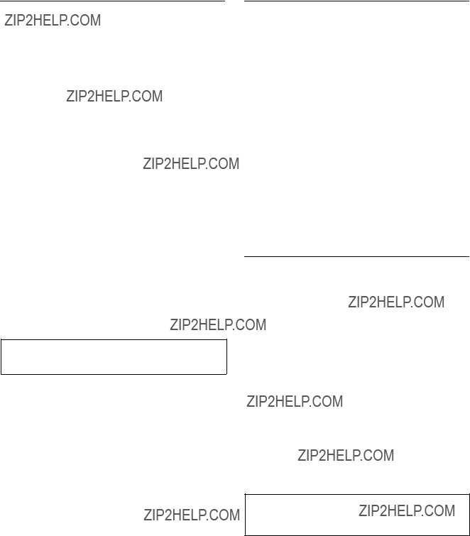
R : CALL SECONDARY STATION
Purpose
This menu is used to call the menu of the secondary station connected to the
Operating Procedure
1.Select the menu item [R] at the menu screen. A message will be displayed on the screen.
2.Enter the station number of the secondary station, and press [Enter]. The display will be changed to the
menu screen of the secondary station.
3.If [Ctrl] _[D] is pressed, the screen will return to the menu screen of the primary station.
m
1.If the specified secondary station does not exist on the
Display: ???Station dose not exist???
2.If the specified secondary station is not
available for communication, the following message will be displayed.
Check at the menu item [F : SET ACTIVE UNIT NUMBER].
Display: ???Disable Station???
CALL STATION NUMBER ? ???
???
Setting Screen
S : SELECT INDICATION COLOR
(Except for
Purpose
If this menu is set to ???ON???, the screen will show a color display during the use of the Sony control terminal BAC- 1200.
Setting Procedure
1.Select menu item [S].
2.When [S], [Enter] is pressed, the setting condition displayed will be switched (???ON??? ??? ???OFF??? ??? ???ON???
...).
n
As wrong characters will be displayed before and after the menu items when a control terminal except Sony control terminal
T : SET CLOCK
Purpose
This menu is used for the setting of the time. The time set at this menu will be used for recording the time of error occurrence.
Setting Procedure
1.Select menu item [T].
2.Enter the time using the numerical keys, and press [Enter] to set it.
The screen will be changed to the menu screen automatically.
n
If [Ctrl] _[E] is pressed without pressing [Enter], the screen will return to the menu screen and the setting modification becomes invalid.
???
Example of Setting Screen

U : SELECT REMOTE
Purpose
This menu is used to control the routing switcher using the
Setting Procedure
1.Select menu item [U].
2.Select channel using the cursor keys.
3.Press [Enter], and the setting condition displayed will
be changed.
DIRECT ??? CONVERT RS422 (CART +) to
Example of Setting Screen
DIRECT:
In this mode commands received using
CONVERT
This mode converts commands received using the RS- 422A to those for the
n
How to use UA2 Code:
The original use of the UA2 code in the
Each equipment is controlled by the control command with UA2 code which corresponds to the unit address of each equipment.
The UA2 code is converted to the level control command when the
The following examples show how UA2 codes are con- verted to the
UA2 = 01 ??? 00000001 ???
The following combinations of levels are also possible.
UA2 = 03 ??? 00000011 ???
n
The

Setting Procedure
1.Select menu item [V].
2.Press [V], [Enter], and the setting conditions dis-
played will be switched.(???ON??? ??? ???OFF???). ???OFF??? : Displays important messages only
<Reference>
???TEMPERATURE RISE IN STATION **???
???TEMPERATURE RECOVERED IN STATION **???
???FAN STOP IN STATION **???
???FAN RECOVERED IN STATION **???
???ON??? : Displays all messages
Displays the following in addition to the above <Reference>
???BACKUP POWER SUPPLY DOWN IN STATION
**???
???BACKUP POWER SUPPLY RECOVERED IN STATION **???
???MISSING REFERENCE SIGNAL IN STATION **???
???REFERENCE SIGNAL CORRECTLY FED TO STATION **???
???VALID INPUT OR OUTPUT BOARD IN STA- TION **???
???INVALID INPUT OR OUTPUT BOARD IN STA- TION **???
???BACKUP CPU DOWN IN STATION **???
???BACKUP CPU RECOVERED IN STATION **???
???STATION **FAILURE (DISCONNECTED OR
POWER DOWN)???
???STARTED BY
**???
???DIFFERENT CHECK SUM=35DB IN STATION **???
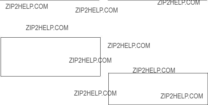
W:SYSTEM STATUS LOG
Purpose
This menu is used to check the error during
Example of Display
Operation Procedure
1.Select menu item [W].
2.When all status cannot be displayed on the screen,
??? __more __??? will be displayed at the bottom of the screen. Press [SPACE] key to display the next
status. When all status have been displayed, ??? __end
__??? will be displayed.
3.Press [Ctrl] _[E] to return to the menu screen.
System Status Screen
Refer to ???6. Confirmation of Function??? for detail of the system status screen.
n
.To erase the LOG contents in
After erasing, be sure to return the S3 switch to ???0??? and press the S5 switch (Reset) again.
.To erase the LOG contents in
After erasing, be sure to return the S2 switch to ???0??? and press the S8 switch (Reset) again.
X : DISPLAY
Purpose
This menu is used to display the
Setting Procedure
1.Select menu item [X].
2.To stop the scroll, press [Ctrl] _[E]. (???TRACE OFF??? will be displayed at the bottom of the screen.)
3.The menu screen will be returned when [Ctrl] _[E] is pressed again.
Example of Display
n
For details on the contents of the display, refer to the S- BUS Protocol Manual.

Y : DISPLAY TABLE (Except for
Purpose
This menu is used to display the table data set with the control terminal.
Operation Procedure
1.Select menu item [Y]. The following message will be displayed at the bottom of the screen.
Display : ???DISPLAY TABLE DATA? (y/a/n)???
2.Press [E], and the signal format (4: 2: 2/4 fsc) set for each input/output will be displayed in hexadecimal.
Press [A], and all table data will be displayed in
hexadecimal.
When [N] is pressed, the table data display will be canceled.
3.If [SPACE] is pressed during the display, the display will be interrupted. When [SPACE] is pressed once
again, the display will begin.
4.Press [Ctrl] _[E] to stop the display. The menu screen will be displayed.
Example of Display
n
For the contents of the table data, refer to the
Z : SET UNIT DETECTABLE
Purpose
This menu is used to check the possibility of communica- tion of secondary stations connected to the
During checking, ??????? appears. After the completion of checking, the code number indicating the type of each device appears.
If the secondary station does not communicate for a given period, the message below appears.
???STATION ***FAILURE (DISCONNECT OR POWER DOWN)???
Station number
Setting Procedure
1.Select the menu item [Z].
2.Select a secondary station you want to check using the cursor.
3.Press [Enter], and ??????? appears.
To cancel ???????, press [Enter] again.
4.Press [Ctrl] _[E], and the display is changed to the menu screen to begin checking.
5.After about ten seconds, select the menu item [Z]. If the secondary station is available for communication, ??????? changes to a device code number.
n
A secondary station to be checked should be set available for communication in advance at menu item [F : SET
ACTIVE UNIT NUMBER]
Example of Setting Screen

A:SET UNIT LOCATION
Purpose
This menu is used to set the input/output location of the routing switcher.
Setting Procedure
1.Select menu item [A].
2.Use the cursor keys ([&], [*] to select the setting item.
3.When [Enter] is pressed, the offset value of the input number and the output number can be typed.
4.Enter the offset value using the numerical keys.
5.Press [Enter] to set the offset value.
If [Ctrl] _[F] is pressed before the setting, the original offset value will be returned.
The location is assigned consecutive numbers from the offset value. The following table lists the input and output control area assigned from the head number consecutively.
m
1.In the initial status (factory setting), the head number is set to ???1???.
2.When
PHYSICAL ASSIGNMENT].
The setting values in this menu are physical input/ output/level numbers.
When selecting crosspoints from the remote control unit, the virtual input/output/level numbers set at the menu item [L] are used. In the initial status of [L], the physical numbers equal the virtual numbers.
512
(Output)
6.The menu screen of the secondary station will be displayed when [Ctrl] _[E] is pressed.
Example of Setting Screen

G:UPDATE BACKUP CONTROLLER
Purpose
This menu is used to copy the table data stored in the main CPU board of the secondary station to the backup CPU board.
This setting is valid only when the optional CPU board is installed to the secondary station.
Setting Procedure
1.Select menu item [G]. The message ???This process requires about 1 minutes. Execute? (y/n)??? will be displayed at the bottom of the screen.
2.Table data copying is performed when [Y] is pressed. To cancel copying, press [N].
3.In some software, when copying has been completed,
???PROGRAM TABLE ok? (y/n)??? may be displayed at the same position. In this case, press [Y].
m
1.The ROM version of the main CPU board and that of the backup CPU board must be the same. If different versions are used, the unit may hang up due to copy- ing. Remove the backup CPU board when this occurs. The above occurs because a new table data can not be run on the old version software.
2.It takes about 1 minutes to copy the table data.
3.The table data of transcode from
4.When you copy the data of main CPU to backup CPU on the menu screen [G : UPDATE
BACKUP CONTROLLER] of the primary station or a
secondary station, you can abort the operation by pressing [Ctrl] _[D].
However you should copy again for the data of the backup CPU is not correct if aborted. Even if you do not copy again, the data will be renewed in one hour approximately by the auto backup function.

H : SET PHANTOM TABLE
Purpose
This menu is used to set PHANTOM which switchers several crosspoints, using the source selection button of the remote control unit.
Setting Procedure
1.Call the menu screen of the remote control unit to be set, using menu item [R], and then select menu item [H].
2.Select a item using the cursor.
3.When [Enter] is pressed, the phantom table can be set. If [Enter] is pressed before setting, the registration
will be deleted.
4.Input the data to the phantom table. The phantom function consists of the global phantom function registered at the primary station, the normal type of local phantom function registered at each remote control unit and the destination off set type of local phantom function.
. Setting the Global Phantom Function
Input the phantom name with the type name and the number. Next, press [G] at destination name position. Lastly, input the global phantom number (four digits) set at the primary station.
.Setting the Normal Type of Local Phantom Function
a)At [J : NAME STYLE (Type +Num)] in the primary station menu item [J], input the type name (between 0 and F) and the number for the phantom name, destination name, source name and level number respectively. (When the remote control unit button is pressed, crosspoints with the same phan- tom name will be switched together.)
b)At [J : NAME STYLE (DESCRIP. NAME)] in the primary station menu item [J], input the phantom name and level number in the same way as a). For the source name and destination name, the Descrip-
tion name and ???Type +Number??? name can be
selected freely.
Each time [Ctrl] _[N] are pressed, the Description name input mode and ???Type +Number??? name input mode will be switched alternately.
Description name input mode :
Use the alphabet and numerical keys to enter seven characters from the head of the Description name.
???Type +Number??? name input mode : Input in the same way as a).
ROUTING SWITCHER SYSTEM (E)
n
If a Description name has been set for the input/output number, the display of Description has priority to the display of ???Type +Number??? even if the ???Type +Number??? name is set.
Example of Setting Screen (Normal Type)
.Setting the Local Phantom of the Destination Offset Type
Enter the phantom name, source name and level number in the same way as the ordinary local phantom.
When [+] is depressed while the cursor is positioned in the DESTINATION column, the system enters the Replace- ment Variable ???DST +n??? input mode. Enter the offset value ???n??? in this status.
Example of Setting Screen (Destination Offset Type)

5.When [Enter] is pressed, the phantom table will be set.
6.When [Ctrl] _[E] is pressed, the menu screen of the secondary station will be displayed. When [Ctrl] _ [D] is pressed, the menu screen of the primary station
will be displayed.
. Execution of Phantom Function
When the phantom function is performed by a remote control unit, its operation conforms to this phantom table. It is possible to switch with the specified level or to set ON
(1) or OFF (0) for each level. When level ???0??? is set or when ???0??? is set for all levels, the level value will that set for the destination name specified in the phantom table. The indication (specified on the menu item [E : SET LEVEL TABLE] of the primary station) is as follows : [Phantom name : Output terminal name < input terminal name ??? level setting].
Internal Process After TAKE Button Pressing :
When pressing the TAKE button after selecting a source/ phantom the following internal process is made. In BKS- R1607/R1608/R3209/R3210, TAKE is processed immedi- ately by pressing the source selection button.
TAKE button is pressed
Checks if the selected name exists on the phantom table
Output the global Select the source/destination phantom number set in the phantom table
Check if the secret or protect is set to the selected source and destination
Omit the source and destination to which the secret or protect is set
Check the level setting of the remaining source and destination for each name.
If the setting is 0, the level is transferred from the destination table
K : RESET TO DEFAULT TABLE
K : DEFAULT TABLE
Purpose
This menu is used to initialize the table data. Do not perform this menu when modifying the table data.
Setting Procedure
1.Select menu item [K]. The message ???RESET TO DEFAULT TABLE ok ? (y/n)??? will be displayed at the bottom of the screen.
2.Press [Y] to process the initialization. To cancel initializing, press [N].
n
The table data will be lost note when performing the menu item [K].
L : COPY TABLE DATA
Purpose
This menu is used to copy the table data of the specified remote control unit. This applies to the remote control unit as follow.
. Version 3.00 or later :
. Version 1.00 or later :
Setting Procedure
1.Select menu item [L]. This item can be selected from both the menu and another setting screen.
2.As the message ???Station Number???? will be displayed on the screen, input the station number of the unit to be copied. Select the table name to be copied, from A, P, B and D, using the alphabet keys.
3.When [Enter] is pressed, the table data will be copied, and the screen will return to the setting screen.
4.When [Ctrl] _[E] is pressed again, the screen will
return to the menu screen of the secondary station. When [Ctrl] _[D] is pressed, the screen will return to
the menu screen of the primary station.
SONY ROUTING SYSTEM SETUP MENU
???
???
???
???
A:Copy All table??? P:Copy PHANTOM table??? B:Copy PANEL table???
D:Copy Available Destination table??? Inputs
Station Number ????
???
ROUTING SWITCHER SYSTEM (E)
Example of Setting Screen
Selected = A All the table data are copied.
Selected = P Data set at the menu item [H : SET PHAN- TOM TABLE] are copied.
Selected = B Data set at the menu item [N : SET PANEL TABLE] are copied.
Selected = D Data set at the menu item [O : SET AVAIL- ABLE DESTINATION] are copied.
n
The copy function of
The remote control unit except for
The function is effective when copying the data from Ver. 1.**unit to Ver. 3.**unit in a system.

M:SET MONITOR FUNCTION (Except for
Purpose
This menu is used to set the monitor
Therefore, it is necessary to set the primary station and secondary stations for the monitor
Setting Procedure
(For the Primary Station on the Monitor
1.Select menu item [M].
2.The menu screen of the primary station on the monitor
For details of setting this menu, refer to
Example of Setting Screen
N : SET PANEL TABLE
Purpose
This menu is used to assign source name to each source selection button.
Setting Procedure
1.Select menu item [N].
2.Select a button number using the cursor.
3.When [Enter] is pressed, the source name can be typed. If [Enter] is pressed before inputting the
source name, the registration will be deleted.
4.Select the code assigned to each type name, and use the numerical keys to enter the source name.
5.Press [Enter] to set the source name.
6.Press [Ctrl] _[E] to return to the menu screen of the
secondary station.
Press [Ctrl] _[D] to return to the menu screen of the primary station.
Example of Setting Screen

N : SET PANEL TABLE
Purpose
This menu is used to assign source/destination name to each source/destination button.
Setting Procedure
1.Select menu item [N].
2.Select a button number using the cursor.
3.When [Enter] is pressed, the panel table can be typed. To delete the registration, press [Enter] before
inputting the name.
4.a) When [J : NAME STYLE (Type +Num)] is selected in the primary station menu, input the type name (between 0 and F) and the number for the source and destination name.
b)Each time Ctrl N is pressed when [J : NAME STYLE (DESCRIP. NAME)] is selected in the primary station menu, the following input mode will be switched alternately.
Description name input mode :
When ???Ctrl _N : Type +Num??? is displayed on the
screen, it means that the name mode will be changed to ???Type +Number??? by pressing [Ctrl] _
[N].
Input Description name from the first to seventh characters using the alphabet and numerical keys.
???Type +Number??? name input mode: Input in the same way as a).
n
If the Description name has been set for the input/output number, the display of Description has priority to the display of ???Type +Number??? even if the ???Type +Number??? name is set.
5.When [Enter] is pressed, the source name is set.
6.When [Ctrl] _[E] is pressed, the menu screen of the
secondary station will be displayed.
When [Ctrl] _[D] is pressed, the menu screen of the primary station will be displayed.
Example of Setting Screen
m
1.In the
Be sure to set either source or destination on the respective buttons (keys) when setting other model. If both source and destination are set to the same button (key), it will cause malfunction.
2.Set the table data of
____PANEL STATUS]. If ???KEY = ____??? is displayed on the key number position, the name can not be input.
3.When setting description names to the source/destina- tion buttons, select a name from the description name group sent to the remote control unit.
If other names are input, these will not be set even if the [Enter] button is pressed.
In such cases, transfer the group including the desired description name from the primary station.

4.When ???T : TAKE M : MONI??? is displayed on the screen, it means that the button on the source side can
be set as the TAKE button or MONI button.
Before pressing [Enter], select a key from the source side. To set it as the TAKE button, press [T]; to set it as the MONITOR button, press [M].
5.When ???V : VTR??? is displayed on the screen, it means that the VTR control function can be assigned to the
buttons on the source side.
Before pressing [Enter], select a key from the source side and press [V].
Enter the number according to the list of operations on the bottom of the screen.
6.When ???E : LEVEL??? is displayed on the screen, it means that the level control function can be assigned
to the buttons on the source side.
Before pressing [Enter], select a key from the source side and press [E].
Enter the number according to the list of levels on the bottom of the screen.
n
In
When this setting is performed, the name selected by the SELECTOR knob on the front panel can be taken by pressing the TAKE button.
(Maximum inputs 512 xoutputs 512)
The actual setting procedure is as follows. Select a key from the source side which you want to use as the TAKE button. Press the [T] button.
Example of Setting Screen
N : SET PANEL TABLE
Purpose
This menu is used to assign source name and destination name to be displayed.
Setting Procedure
The setting procedure is the same as that of menu item [N : SET PANEL TABLE]
m
1.The setting of [SET PANEL TABLE (SOURCE)] assigns the source name and [SELECT DESTINA- TION] assigns the destination name.
2.The destination name can also be assigned using the button on the front panel. Refer to the Operation Manual for setting.
3.If ???Type +number??? name mode is selected in the menu item [Z : SET PANEL STATUS], (refer to the Operation Manual of
Example of Setting Screen
Example of Setting Screen
ROUTING SWITCHER SYSTEM (E)
4.Press [Ctrl] _[F] to switch to the display allowing setting of the selectable sources.
Pressing [Ctrl] _[E] switches to the menu screen of
the secondary station.
Pressing [Ctrl] _[D] returns to the menu screen of the primary station.
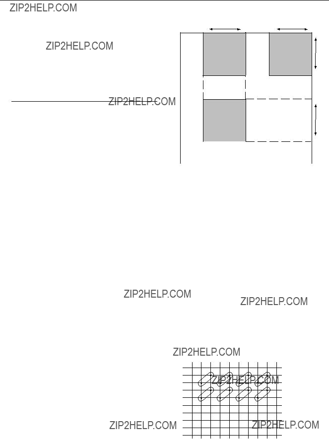
.Procedure of setting SELECT SOURCE NAME
1.Select an item to set using the cursor key.
2.Pressing [Enter] establishes the source name input mode.
3.Enter the ???Type +No.??? name or description name.
4.Press [Enter] to confirm the input contents.
Example of setting
When the ranges of input and output selections are limited as shown in the above table, the setting display and the virtual matrix are configured as shown below.
Example of Setting Screen
(Setting the range of selectable sources)
n
In
64
101
Block 3
m
1.When selecting the destinations that have no limit of range, the selectable range of sources is from 001 to 1024.
2.
In
Odd number : Source
Even number : Key
1
2
3
4
5
6
7
8
9
(Output)
ROUTING SWITCHER SYSTEM (E)

Example of setting :
SRC
When you want execute the combinations of OUT001<IN001 and OUT002<IN002, or the combinations of OUT003<IN001 and OUT004<IN002, enter as follows.
Phantom:
IN001:
IN001:
Here, 10000000 means the
When the above settings are performed and the buttons OUT001 and IN001 are pressed in this order, OUT001 is replaced by OUT002 with DST+1.
Then,
OUT001<IN001
OUT002<IN002
of the
When the buttons OUT003 and IN001 are pressed in this order,
OUT003<IN001
OUT004<IN001
of the
When OUT005 and IN001 are pressed, DST+0<IN001- 10000000 (i.e., OUT005<IN001) only are switched since it is outside the applicable range.
Set the phantom for IN003, IN005 and IN007 in the same way.
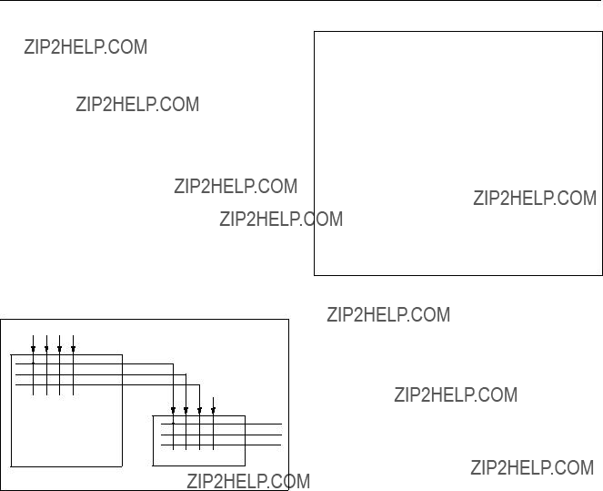
R : SET ROUTE
Purpose
This is the function to display the source names that are expanded by combining the two switchers for the purpose of expanding numbers of input.
When a route is set, the source that is connected to the route destination, is automatically chased out the and the name of the source is displayed. In an example shown below, IN001 of the switcher A is displayed as the source name when OUT017 of the switcher B is selected.
It has another function as follows. When a request of switching including the expanded destination, is issued, crosspoint of the route destination side is automatically switched. For example, when
Route Function
???
Example of Setting Screen
In the setting screen example as shown above, the cross- point of
Setting procedure
1.Select the menu item [R] of the secondary station.
2.Select the desired item using the cursor key.
3.Pressing [Enter] establishes the route setting mode. When [Enter] is pressed again before entering data,
registration is canceled.
4.Enter the ???Type +No.??? name or description name. (The setting methods remains the same as that of phantom. Refer to the description of the secondary station???s menu item [H : SET PHANTOM TABLE]. However, the destination name of the
5.Press [Enter] to confirm the input contents.
6.Pressing [Ctrl] _[E] switches to the menu screen of
the secondary station.
Pressing [Ctrl] _[D] returns to the menu screen of the primary station.
To add the offset amount to the selected destination, enter [+] in the DEST column before pressing [Enter].
After ???DEST +??? is displayed, enter the offset value (0 to 1023) and press [Enter] to store the value.
Each level can be set by selecting ON (1) or OFF (0).
ROUTING SWITCHER SYSTEM (E)

S : DISPLAY DESCRIPTION NAME
Purpose
This menu is used to check the group and names of the Description transferred from the primary station.
Check Procedure
1.When [Enter] or [SPACE] is pressed, the screen will be changed to the next page.
2.When [BS] or [DEL] is pressed, the screen will be changed to the previous page.
3.Press [Ctrl] _[E] to display the menu screen of the
secondary station.
Press [Ctrl] _[D] to display the menu screen of the primary station.
Example of Setting Screen
n
In
The following operations are possible from the screen. Look at destination from source side : [*] key Look at source from destination side : [&] key
Example of Setting Screen

U : SELECT REMOTE PROTOCOL
Purpose
This menu is used to set channels A and B of REMOTE 2
There are three kinds of protocols.
. PRODUCTION SWITCHER PROTOCOL
. AUDIO MIXER PROTOCOL
. CART PROTOCOL
n
AUDIO MIXER PROTOCOL was known as ???SWITCH- ER PROTOCOL??? before.
Set the conversion table of the input/output numbers so that the input/output numbers defined by the external controller will correspond to those of the routing switcher. In the THROUGH mode, there will be no setting menu for channel B. For details of the DIRECT mode, refer to the menu item [U : SELECT CONTROL MODE] in the primary station.
Setting Procedure
n
The same number cannot be set to more than one place. If the same number is used, the message ??? *** is used already; Ignored??? will be displayed and the cursor will stop at its current position.
1.Select menu item [U].
2.???SELECT
displayed. Input A or B using the alphabet keys and press [Enter]. The screen will change to the setting
screen of the selected channel.
3.The cursor will be placed at ???1=001??? of ???SET DESTI-
NATION TRANSCODE???.
When [Enter] is pressed, ???1=??? will be displayed and the number can be typed. The left ???1??? in ???1=001??? indicates the input/output number of the switcher and the right ???001??? indicates the command number received.
4.Input a number between 1 and 128 and press [Enter] set it. The cursor will move to the next number.
If ???00??? is input, ???001??? will be displayed. If number
129 or later is input, the previous number will be displayed. If [Enter] is pressed without inputting
anything, invalid crosspoints will be set so that the
screen will show ??? ?? ?? ?? ?? ???, and the cursor will move to the next number. When [Ctrl] _[F] is pressed before
the setting, the previous number will be displayed and the cursor will move to the next number.
Example of Setting Screen
Operating Function Keys
[F1] : REMOTE (To switch the protocol)
1.When [F1] is pressed, the cursor will move to ???REMOTE???.
2.When [Enter] is pressed, the protocol will be switched. To change the ??? ***??? of ???UA2 =???,
select the desired position with the cursor and press [Enter] to switch 1/0 alternately.
n
The description ??? ***??? of ???UA2 = ***??? on the above menu corresponds to the DIP switch setting which LSB is at the left end.
[F2] : DEFAULT (Initializing the data)
1.When [F2] is pressed, ???DEFAULT ok? (y/n)??? will be displayed at the bottom of the screen.
2.When [Y] is pressed, the program will be executed. When [N] is pressed, it will not be
executed.
[F3] : DEST
When [F3] is pressed, the cursor will move to the
destination side. [F4] : SOURCE
When [F4] is pressed, the cursor will move to the
source side.
ROUTING SWITCHER SYSTEM (E)
V : DISPLAY UNIT STATUS (Except for
Purpose
This menu is used to display the status of the hardware such as boards, etc.
n
For the input/output boards and matrix boards of DVS- V3232B, channel 1 to 32 will be displayed. And FAN 1 and 2 will be displayed for
Operating Procedure
1.Select menu item [V].
2.Press [Ctrl] _[E]. The menu screen will be dis- played.
BINVALID ???
???
???
??? ???
Example of Display
Y : DISPLAY TABLE DATA (Except for
Purpose
This menu is used to display the table data set with the control terminal.
Operation Procedure
1.Select menu item [Y]. The following message will be displayed at the bottom of the screen.
Display: ???DISPLAY TABLE DATA? (y/n)???
2.Press [Y], and the 4:2:2/4 fsc setting value will be displayed in hexadecimal. Press [A], and the table
data will be displayed in hexadecimal.
When [N] is pressed, the table data display will be cancelled.
3.When [SPACE] is pressed during the display, the display will be interrupted. When [SPACE] is
pressed once again, the display will begin.
4.Press [Ctrl] _[E] to stop the display. The menu screen of the secondary station will be displayed.
Example of Display
n
For the details of the table data, refer to the

Y : SET DISPLAY MODES
Purpose
This menu is used to set the display mode.
The setting contents are as follows.
DISPLAY MODES
(DESCRIP.NAME) is selected in the primary station menu.)
NORMAL = Normal display
2 +2CHAR = Displays two letters before and after the name.
4CHAR = Displays four letters from the beginning of the name.
n
If 2 : 2 +2CHAR or 3 : 4CHAR is selected when J : NAME STYLE (Type +Num) is selected in the primary station menu, the two letters and two numbers of the type name are displayed.
PANEL FUNCTION
NORMAL = Normal selection mode
4 DESTINATION = Destinations can be set for each block of the source button that consists of four blocks.
Set each source button and also set the destination of each block using the menu item [N : SET PANEL TABLE].
TALLY GROUP
Selects the tally group.
Setting Procedure
1.Select the menu item [Y].
2.The cursor appears in ???DISPLAY MODES = 1???.
Move the cursor to an arbitrary mode and press [Enter] establishes the input mode.
3.Enter the desired number with the numeric keys. Press [Enter] to set the number ; the cursor moves to
the next setting item.
If you do not want to change the default value, press [Enter] without entering any number.
4.To set ???TALLY GROUP???, move the cursor to the
position of the desired tally (in the case of tally 2, second ??? _??? from the left) and press [Enter]. The item is toggled on and off every time [Enter] is pressed.
(When the number is displayed, the item is ON. When ??? _??? is displayed, the item is OFF.)
???
Example of Setting Screen

Z : SELECT SDI FORMAT (Except for
Purpose
This menu is used to set the format of signals fed to the input/output board of
This setting is available when the manual switch for the format on each input/output board is OFF.
Setting Procedure
1.Select menu item [Z].
2.Select a channel line using the cursor to be set. (The channels will be switched by eight channels. Displayed signal formats that are enclosed by the round brackets as ???(4:2:2)??? have been set on the board and cannot be modified with the control terminal.
3.When [Enter] is pressed, the setting will change (???4:2:2??? ??? ???4 fsc NTSC??? ??? ???4 fsc PAL???).
4.Press [S] (Table Set), and the content now appeared is copied to the area of SDI FORMAT TABLE.
5.Press [Ctrl] _[E] to stop the display and the menu screen of the secondary station will be displayed.
F1:FORMAT 
 F2:FIELD S:Table Set
Example of Setting Screen
n
Unless pressing [S], the data will be deleted when the power is turned off.
Operating Function Keys
[F1] : FORMAT (Mode which sets the signal format by 8- channels)
[F2] : FIELD (Mode which sets the crosspoint switching field)
1.Press [F2]. The cursor will move to ???SWITCH ING FIELD??? in the menu.
2.Press [Enter]. The setting will change. (ODD ??? EVEN ??? FIELD ??? ASYNC ??? ODD)
All switching field in the switcher are deter mined by this setting.
n
To use
1 When using the
ODD
2When using the
Note that the switching timing of the CART will not be accurate if the CART and PRODUCTION SWITCHERS protocols are used together.
Switching timing is not guaranteed in the combination of different switching fields.
For details of the signal switching timing, refer to

Z : SET PANEL STATUS
Purpose
Besides the remote control unit can be used alone, several units can be used together as if it were one unit with expanded sources and destinations. When using several units together, one will serve as the mother and the rest will serve as the daughters.
This menu is used to perform the settings necessary in such cases. The selection of stand alone use, mother use, and daughter use is performed in this menu in addition to the assignment of buttons on the front panel. If assigned as the mother station, a block number should be set. (up to 10 mothers can be registered.)
Setting Procedure
1.Select menu item [Z].
2.Place the cursor on ???PANEL MODE=1??? and press [Enter] to select an item. Selection should be per-
If selection is not necessary, press [Enter] again.
3.Place the cursor on ???KEY
To change to the next setting, press [Enter].
4.When ???PANEL MODE=2??? (the MOTHER) is select-
ed, move the cursor to ???SET BLOCK NUMBER=X??? and press [Enter] to enter block number. When [Enter] is pressed again, the block number will be set.
If the mother station is set, the ID are displayed.
5.When ???PANEL MODE=3??? (the DAUGHTER) is selected on
6.In setting of
name.
???PANEL LAYOUT= x??? is displayed. Press [Enter] and input the numbers.
7.Press [Ctrl] _[E] to display to the menu screen of the
secondary station.
Press [Ctrl] _[D] to display to the menu screen of the primary station.
n
When ???PANEL MODE=1??? (the STAND ALONE) is selected on
SONY ROUTING SYSTEM SETUP MENU???
SET PANEL STATUS???
???
Example of Setting Screen

Example of Setting Screen
Z : SET PANEL STATUS
Purpose
This is the function to set the various modes of the remote control unit. In the models corresponding this menu as shown above the multiple units can be connected in order to expand the number of sources and destinations which can be controlled simultaneously. Setting the mother panel and the daughter panels is performed from this menu. (Maximum ten mother panels can be set.)
Contents to be set are shown below.
DISPLAY MODE
STATUS = Indicates the status of the primary station???s crosspoint table.
PROMPT = The depressed button lit immediately.
PROTECT MODE
ON AIR = Switching is performed from that panel even after protected.
NORMAL = Switching is prohibited after protected. FLEXIBLE = Switching is prohibited after protected.
However, protections by other stations can be released.*1
FLEX & OA =Uses the functions of both 1 : ON AIR and 3 : FLEXIBLE. *1
PHANTOM PROTECT
PART PROT = The phantoms that are not protected are switched.
FULL PROT = All phantoms cannot be switched when even one phantom on which protect is set to on, is included.
BUTTON LINK = All phantoms cannot be switched when the protect button is set to on.
PANEL MODE
STAND ALONE = Stand alone panel
MOTHER = Mother panel
DAUGHTER = Daughter panel
PANEL LAYOUT*2
TYPE +NUM. = Selection of
BPS = Source button selection*1 KEYPAD = Description selection*1
(Only
*1 : It is only applicable to
*2 : It is only applicable to
*3 :

LEVEL MODE*1
SINGLE = Single level selection
MULTI = Multiple level selection
DEST SELECTION*2
DISABLE = Change of destination from the panel is prohibited.
ENABLE = Change of destination from the panel is allowed.
ILLUMINATION LEVEL*3
Brightness of the button indicator : 1 (dark) to 8 (bright)
MONITOR DESTINATION*3
Enter the name of the destination to be monitored (when the MONI button is selected).
SOURCE OFFSET*3
0 = Use the same source as the destination to be monitored. 1 to 1023 = Use the source at the specified offset.
CONTROL LEVELS*3
When you want to select any specific level from remote
control unit, move the cursor to the desired level and press [Enter]. (When you want to select
??? _??? = : Level selection will not be performed.
Other than ??? _??? : A signal will be switched at the level. When all indications show ??? _???, a signal is switched at the level which is set by the primary station.
*1 : It is only applicable to
*2 : It is only applicable to
*3 : It is only applicable to
Setting Procedure
1.Select the menu item [Z].
2.The cursor appears in ???DISPLAY MODE = 1???.
Move the cursor to an arbitrary mode and press [Enter] establishes the input mode.
3.Enter a number to select using the
When [Enter] is pressed to confirm the input number, the cursor moves to the next setting item.
When you do not want to change the default value, do not input any number, but press [Enter].
Example of Setting Screen
4.Set the respective items in the same way as the steps 2 and 3.
However, set ???PANEL MODE??? (setting the mother and daughters panels) as follows.

Mother panel :
1)Select ???PANEL MODE = 2??? (mother machine).
2)Press [Enter].
The following contents are displayed on the setting screen.
3)Input the unused BLOCK number of the BLOCK & MOTHER STATION LIST into the ??? *??? column.
4)Press [Enter] to confirm the input contents.
Daughter panel :
1)Select ???PANEL MODE = 3??? (daughter panel).
2)Press [Enter].
The following contents are displayed on the setting screen.
3)Input the mother???s STATION ID number of the BLOCK & MOTHER STATION LIST into the ??? **??? column.
4)Press [Enter].
When the ID number is input correctly, model name of the mother panel appears as shown below.
n
Checksum can be displayed from version V1.10 of the BKS series.
Use checksum to check if the program data is correct, in addition to the version number indication. (The PGM CHECKSUM is mainly used.)
The following three types of checksum are available.
BOOT CHECKSUM=D039
Checksum of the program area that is used for starting up the ROM.
PGM CHECKSUM=630F
Check of the area in which the actual programs are stored.
ROM CHECKSUM=FF68 Checksum of the entire ROM.
Example of Setting Screen
5.Pressing [Ctrl] _[E] switches to the menu display of
the secondary station.
Pressing [Ctrl] _[D] returns to the menu display of the primary station.
m
1.Various modes must be set individually on the units on which mother panel and daughter panels are set.
2.Set the mother panel first when setting the mother panel and daughter panel.
3.Setting of the mother panel and daughter panel is not completed when the ???PANEL MODE??? setting alone is performed.
Be sure to set the block numbers of mother panel and to set the STATION ID (MOTHER ID) of the daugh- ter panel side.
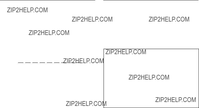
Z : SELECT CONNECTION
Purpose
As for
If a controller is connected to a
When setting to (S), termination is automatically made.
Setting Procedure
1.Select the menu item [Z].
2.Select a input/output number using the cursor.
3.Press [Enter], the setting status changes. (???M??? ??? ???S??? ??? ???M???)
4.Press [S] (TABLE SET), the content now appeared is copied to the table data.
5.Press [Ctrl] _[E] to stop the display and the menu screen of the secondary station will be displayed.
Example of Setting Screen
n
Unless pressing [S], the setting will be ignore.
Z : SWITCHING FIELD
Purpose
This menu is used to set the crosspoint switching field of
Setting Procedure
1.Select the menu item [Z].
2.Press [Ctrl] _[E] to stop the display and the menu screen of the secondary station will be displayed.
???
Example of Setting Screen
n
Unless pressing [S], the data will be deleted when the power is turned off.
Operating Function Key
[F2] : FIELD (Mode which sets the crosspoint switching field)
1.Press [F2]. The cursor will move to ???SWITCH ING FIELD??? in the menu.
2.Press [Enter]. The setting will change. (ODD ??? EVEN ??? FIELD ??? ASYNC ??? ODD)
All switching field in the switcher are deter mined by this setting.
n
To use
1 When using the
ODD
2When using the
Note that the switching timing of the CART will not be accurate if the CART and PRODUCTION SWITCHERS protocols are used together.
Switching timing is not guaranteed in the combination of different switching fields.
For details of the signal switching timing, refer to
ROUTING SWITCHER SYSTEM (E)

Used for setting the units on the monitor
Menu Screen of the Primary Station on Monitor
Setting Procedure of Monitor Function
1.Select the menu item [R] of the primary station in order to call the menu screen of the secondary station set as the primary station on the monitor
2.Select the menu item [M] to call the menu screen of the primary station on the monitor
3.Set the menu item [F] and [M].
4.Select the menu item [R] to call the secondary station on the monitor
5.Set each menu item on the screen.
6.Press [Ctrl] _[Z] to return to the menu screen of the primary station on the monitor
7.Set each item of all secondary stations, repeating the procedure of step 4 to 6.
8.Press [Ctrl] _[D] to return to the menu screen of the primary station on the standard
n
If there are multiple monitor
F : SET ACTIVE UNIT NUMBER
Purpose
This menu is used to enable the units connected to the data link of the monitor
Setting Procedure
1.Select menu item [F].
2.Select the secondary station using the cursor whose communication will be valid.
3.When [Enter] is pressed, the setting displayed will change ???E??? ??? ???Blank??? ??? ???E???. Only the secondary
stations displayed with ???E??? are valid. (???M??? indicates the primary station.)
4.When [Ctrl] _[E] is pressed, the menu screen of the primary station on the monitor
n
As the response will become slower if there are many secondary stations, make the secondary stations not connected invalid.
??? *??? indicates out of the control area.
Example of Setting Screen
m
1.Station ID of the primary station is always 1 regardless of the DIP switch setting on the CPU board.
2.Station ID of the secondary station is deter mined with the DIP switch setting. Do not assign the same number on two or more units as station ID on both standard
Number that can be registered as secondary s station ID are 2 to 254.

M: SELECT MONITOR FUNCTION
Purpose
This menu is for setting the connection to use the input monitor and output monitor in series or independently. To monitor the input and output monitor lines using separate monitors, set the SEPARATED mode. To monitor them together on one monitor, set the COM- BINED mode.
Setting Procedure
1.Select menu item [M]. The following appears.
COMBINED : series connection
SEPARATED : independent use
2.Press [Ctrl] _[E] to display the menu screen of the primary station on the monitor
R : CALL SECONDARY STATION
Purpose
This menu is used to call the secondary station on the monitor
Setting Procedure
1.Select menu item [R].
2.Enter the station number using the numerical keys, and press [Enter] to call it.
3.The menu screen of the secondary station on the monitor
M:SET AVAILABLE MONITOR LINE
M: SET AVAILABLE MONITOR LINE INPUT=( ENABLE )OUTPUT=( ENABLE )???
???
???
Menu Screen of the Secondary Station on Monitor
Purpose
This menu is used to set the input monitor and output monitor to valid or invalid.
Setting Procedure
1.Select menu item [M].
2.Select the source/destination using the cursor, and press [Enter] to change the setting. (???ENABLE??? ??? ???DISABLE??? ??? ???ENABLE???)
3.Press [Ctrl] _[Z] to display the menu screen of the primary station on the monitor
n
Be sure to set the monitor line to ???DISABLE??? in cascade connection.
If set to ???ENABLE???, the monitor may not be performed properly.
L : COPY TABLE DATA <MONITOR MENU>
Purpose
This menu is used to copy the setting contents of the remote control unit. This is applied to
Setting Procedure
1.Select menu item [L]. This item can be selected from both the menu and another setting screen.
2.The message ???Station Number???? will be displayed. Enter the station number to be copied.
3.When [Enter] is pressed, the table data will be copied
and the screen will return to the setting screen. When [Ctrl] _[E] is pressed again, the menu screen
of the secondary station on the monitor
4.When [Ctrl] _[Z] is pressed, menu screen of the primary station on the monitor
Station Number ????
???
Example of Setting Screen
Data set on the menu item [N : SET PANEL TABLE] are copied.

N : SET PANEL TABLE
Purpose
This menu is used to assign source/destination name to each source/destination selection button.
In the monitor mode, the button color of the remote control unit will be green for both source and destination.
Setting Procedure
1.Select menu item [N].
2.Select a button number using the cursor.
3.When [Enter] is pressed, the name can be typed. To delete the registration, press [Enter] before
inputting the name.
4.a) When [J : NAME STYLE (Type +Num)] is
selected in the primary station menu, input the type name (between 0 and F) and the number for the source and destination.
b)Each time [Ctrl] _[N] is pressed when [J : NAME STYLE (DESCRIP. NAME)] is selected in the primary station menu, the following input modes will be switched alternately.
Description name input mode :
When ???Ctrl N: Type +Num??? is displayed on the
screen, it means that the name mode will be changed to ???Type + Number??? by pressing [Ctrl] _[N].
Inputs the Description name from the first to seventh characters with alphabet and numerical keys.
???Type +Number??? name input mode : Same as a)
n
If the Description name has been set for the input/output number the display of Description has priority to the display of ???Type +Number??? even if the ???Type +Number??? name is input.
5.When [Enter] is pressed, the source name is set.
6.When [Ctrl] _[E] is pressed, the screen will return to the menu screen of the secondary station on the
monitor
When [Ctrl] _[Z] is pressed, the screen will return to the menu screen of the primary station on the monitor
When [Ctrl] _[D] is pressed, the screen will return to the menu screen of the primary station on the standard
Example of Setting Screen
m
1.Set the table data of
____PANEL STATUS]. If ???KEY = ____??? is displayed on the key number position, the name can not be input.
2.Be sure to set either source or destination on the respective buttons (keys) when setting the BKS- R1607/R1608/R3209/R3210.
If both source and destination are set to the same button (key), it will cause malfunction.
3.When setting description names to the source/destina- tion buttons, select a name from the description name group sent to the remote control unit.
If other names are input, these will not be set even if the [Enter] button is pressed.
In such cases, transfer the group including the desired description name from the primary station.

S : DISPLAY DESCRIPTION NAME
<MONITOR MENU>
n
In
When this setting is performed, the name selected by the SELECTOR knob on the front panel can be taken by pressing the TAKE button.
(Maximum inputs 512 xoutputs 512)
The actual setting procedure is as follows. Select a key from the source side which you want to use as the TAKE button. Press the [T] button.
Example of Setting Screen
Purpose
Check the groups and their names of the description names that are transferred from the primary station.
Check Procedure
1.Press either [Enter] or [SPACE] to view the next page.
2.Press either [BS] or [DEL] to view the previous page.
3.Press [Ctrl] _[E] to return to the menu screen of the
secondary station.
Press [Ctrl] _[D] to return to the menu screen of the primary station.
Example of Setting Screen

n
In
The following operations are possible from the screen. Look at destination from source side : [*] key Look at source from destination side : [&] key
Example of Setting Screen
Z : SET PANEL STATUS
<MONITOR MENU> Purpose
Set the various modes of the remote control unit.
Number of sources and destinations that can be controlled from the remote control unit, can be expanded by connect- ing multiple mother and daughter panels. Setting the mother and daughter panels are also performed using this menu. (Ten mother panels can be registered at the maxi- mum.)
The setting contents are as follows.
DISPLAY MODE
STATUS= Displays the status of the primary station crosspoint table.
PROMPT= The pressed buttons lit immediately.
PROTECT MODE
ON AIR= Execute switching from the panel even during the protect mode.
NORMAL= Switching is not possible during the protect mode.
PHANTOM PROTECT
PART PROT= Execute switching on the phantom on which protect is not set.
FULL PROT=Switching is not executed on all phantoms when any of the phantom is set to PRO-
TECT ON.
BUTTON LINK= Switching is not executed on all phantoms when the PROTECT button on the panel is set to ON.
PANEL MODE*3
STAND ALONE= Stand alone panel
MOTHER= Mother panel
DAUGHTER= Daughter panel
PANEL LAYOUT*1
TYPE + NUM.= Selecting
DIRECT= Selecting direct
LEVEL MODE*1
SINGLE= Selecting a single level
MULTI= Selecting multiple levels
DEST SELECTION*2
DISABLE=The destination change from panel is disabled.
ENABLE=The destination change from panel is enabled.
*1: Applicable to
*2: Applicable to
*3: When monitor

Setting Procedure
1.Select menu item [Z].
2.The cursor appears at ???DISPLAY MODE=1.???
Move the cursor to the desired mode. (Use the keys [(], [)].) Press [Enter] to enter the input mode.
3.Input the number to be selected using the numerical
keys.
Press [Enter] to set the input number. The cursor moves to the setting item.
When you want to modify the default value, press [Enter] without inputting any number.
Example of Setting Screen
n
Checksum can be displayed from version V1.10 of the BKS series.
Use checksum to check if the program data is correct, in addition to the version number indication. (The PGM CHECKSUM is mainly used.)
The following three types of checksum are available.
BOOT CHECKSUM=D039
Checksum of the program area that is used for starting up the ROM.
PGM CHECKSUM=630F
Check of the area in which the actual programs are stored.
ROM CHECKSUM=FF68 Checksum of the entire ROM.
Example of Setting Screen

The data set using the control terminal will be stored in the RAM on the CPU board. It is however recommended that the setting data be backed up just in case the data is damaged or lost.
Data can be backed up easily by using the Sony routing switcher system control software
If the LED (D7) on the CPU board is not lit even if the error No. indicator shows ???00??? when operations are being checked, it means that all the data set have been lost.
The first thing to do is to check the setting of COR1 on the CPU board. OFF : Set to ON position.
ON : The lithium battery (BT1) may be defective.
Measure voltage across BT1. If it is 2V or less, replace it with the new one. Consult with your Sony Sales Representative for replacement of battery.
Next, initialize the unit as following procedures.
1.Set the COR1 on the
2.Set the test switch (S3) to ???D??? and press the reset switch (S5).
3.Set the test switch (S3) to ???0??? and press the reset switch (S5).
4.Call the menu screen on the control terminal and execute the menu item [T : SET CLOCK].
If the LED (D2) on the CPU board is not lit even if the error No. indicator shows ???00??? when operations are being checked, it means that all the data set have been lost.
The lithium battery (BT1) may be defective.
Measure voltage across BT1. If it is 2V or less, replace it with the new one
If the LED (D13) on the CPU board is not lit even if the error No. indicator shows ???00??? when operations are being checked, it means that all the data set have been lost.
The first thing to do is to check the setting of the CN5 on the CPU board. OFF : Set to ON position.
ON : The lithium battery (BT1) may be defective.
Measure voltage across BT1. If it is 2V or less, replace it with the new one. Consult with your Sony Sales Representative for replacement of battery.
Next, initialize the unit as following procedures.
1.Set the COR1 on the
2.Set the test switch (S2) to ???D??? and press the reset switch (S8).
3.Set the test switch (S2) to ???0??? and press the reset switch (S8).
4.Call the menu screen on the control terminal and execute the menu item [T : SET CLOCK].

There are five ways of initializing the table data. Note that the way to be used depends on which item is initialized.
11. Set the test switch (S3) on the
2. Press the reset switch (S5).
All items of the primary and secondary stations.
11. Set the test switch (S5) on the
2. Press the reset switch (S1).
All items of the primary and secondary stations.
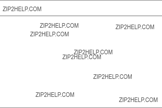
11. Set the test switch (S2) on the
2. Press the reset switch (S8).
All items of the primary and secondary stations.
n
The primary station of
The secondary station of the menu item [Z] of [SWITCHING FIELD] only.
For
The signal switching timing depends on whether it is controlled by
The following shows the timing charts of
. When SWITCHING FIELD ???EVEN??? is set
. When SWITCHING FIELD ???ODD??? is set
. When SWITCHING FIELD ???FIELD??? is set
.When SWITCHING FIELD ???ASYNC??? is set
The signals will be switched immediately after the switching command is received regardless of the control method and protocol used.
Section 6
Confirmation of function
After the hardware and software have been set up, it is necessary to check if the system is working properly before starting the operation.
Each routing switcher is equipped with the
1.Status indicator
2.System status screen (*)
3.Error No. indicator
4.LEDs on the boards
Moreover, the test mode and ISR function are available to find out the detail of error and cause.
This section outlines the checks performed when the system is started up, and describes error messages displayed on [2. System status screen] in detail.
For details of [1. Status indicator], [3. Error No. indicator] and ISR function, refer to the operation manual or maintenance manual provided with the unit. For [4. LEDs on the boards] and [Test mode], refer to the maintenance manual.
*: The error messages displayed in [2. System Status Screen] are valid only when the control terminal is connected to the primary station in the

The contents of each function and the structure of the error displays are as follows.
LED Display for Internal Information
LED displays the presence/absence of the signals and setting of the switches independently, irrespective of the self- diagnosis and test mode.
Test Mode Function
Test mode is effective for finding the causes of the error and the faulty sections which have been detected by the
Function Check
Contorl Terminal (System Status Screen)
The
*1 :

Error No. Indicator*1
00 Operating normally
6 * Faulty sync signal detection
4 * Faulty crosspoint hardware
7 * Increase in the switcher's internal temperature/Fan has stopped
2 * Communication error of the REMOTE 1 connector
8 * ROM/RAM/EEPROM check error or table deta reading error
1 * Communication error of the REMOTE 2 connector
3 * Communication error of the REMOTE 3 connector
5 * Incorrect setting data of the backup memory
FF Malfunction of CPU board
*1 :

*1 :
*2 :

After installing the hardware and software of the routing switcher system, check its functions and those of each device according to the following procedures. The process of the function check consists of three steps. The checks in step 2 and onward will be performed only when errors have been detected in step 1. If not, the checking process ends there. When errors have been displayed in step 1, except the cases that causes are found with the display contents, it is necessary to find out the faulty sections and causes by performing the checks from step 2. Countermeasures and the methods of fixing the errors are described in detail in the operation manuals and maintenance manuals provided. For the
1 Turn on the power of the
8 Completion of function check

There are two types of display modes for operation check from control terminal, which can be selected depending upon the purpose. The first type of display mode is provided by the system status display and the other is provided by the ???W??? menu on the menu display.
The system status display shows result of self diagnostics that is performed automatically by the primary station when the main power of the system is turned on. It also shows error messages that are issued by the respective stations on the
To check the old system status, call the menu item [W: SYSTEM STATUS LOG].
This menu takes out only the system status from the memory, and displays error messages, corresponding station and time of occurrence.
n
As the control terminal constantly checks the errors of the system, and is capable of recording/displaying these, it is extremely effective for monitoring the operations of the system. Therefore, it is recommended to connect this control terminal after completing initial settings.
When the power of the primary station is turned on, the results of the
If the result of the
Example of the System Status Screen After Power On
Display Contents:
1 ROM checksum value on the CPU board of the primary station.
2 Condition of the reading/writing operations of the RAM in the primary station. 3 The result of detecting the reference signal in the primary station.
4 Presence of the 75 Ztermination in the

When a message is output to the

Error message
 Error message
Example of System Status Screen During System Operation
On the other hand, the menu item [W: SYSTEM STATUS LOG] can be used to call all the error informa- tion stored in the RAM of the primary station, such as the content and time of errors in each station and on the
Operating procedure:
1.Turn on the power supply of the primary station to automatically start up the system status screen.
2.Press [Ctrl] _[X] to display the menu screen.
The password will be requested if it has been set. Input the password using the numerical and alpha- bet keys, and press [Return] or [Enter] .
3.Select the menu item [W].
4.??? __more __??? will be displayed at the bottom of the screen if all error contents cannot be displayed
on a screen.
Press [SPACE] to display the next error content. ??? __end __??? will be displayed when all error contents have been displayed.
5.Press [Ctrl] _[E] to return to the menu screen.
6.Press [Ctrl] _[X] to return to the system status screen.

The control terminal will display eleven types of error messages according to the error content. However, depending on the model, some are not used because of no detection, or some part of the message may differ. For details of the messages and their countermeasures, refer to operation manuals provided with each model.
Standard error messages and their countermeasures are as follows.
Content : Faulty crosspoint hardware
As a result of comparing the presence/absence of the crosspoint signal in the station being displayed, this message will be displayed if the input signal was found to be present without the output signal, and vice versa, or if the input/output board has not been inserted correctly.
Countermeasure : The crosspoint of station ***is faulty. Check the input/output board has been properly installed.
TEMPERATURE RISE OR FAN STOP IN STATION * * *
Content : This message is displayed when the temperature inside of the station being displayed has risen, or when the fan has stopped.
Countermeasure : Promptly turn off the power supply of station ***, and check for
MISSING REFERENCE SIGNAL IN STATION * * *
Content : This message is displayed when the SYNC/ASYNC select switch on the CPU board of the switcher has been set to the sync switching mode (SYNC), and the reference video signal has not been input to the REF IN connector.
Countermeasure : Connect the sync signal to the REF IN connector of station ***.
n
Set the SYNC/ASYNC select switch to ???ASYNC??? if the reference signal is not present. When the reference signal is not input in the sync switching mode (SYNC), the crosspoint is switched automatically as the async switching mode (ASYNC).
CHANGED OVER TO BACKUP POWER SUPPLY IN STATION * * *
Content : This message is displayed when the power supply output during operations has dropped and it is changed over to the backup power supply.
Countermeasure : Remove the faulty power supply of station ***, and repair or replace it with a new one.

DIFFERENT CHECK SUM= ???? IN STATION * * *
 Check sun value
Content : This message is displayed when an error has been detected as the result of ROM checksum and RAM writing tests performed after resetting the unit.
Countermeasure : Replace the corresponding ROM.
n
This error message will be displayed even after the ROM has been replaced. This is normal. Execute the menu item [J: RECALL MAIN TABLE] from the control terminal, and reset the corresponding unit once again for the unit to begin operating normally.
Content : This message is displayed when the
Countermeasure : Check the connections between the
n
Be sure to terminate unused
CHANGED OVER TO BACKUP CPU IN STATION * * *
Content : This message is displayed when an error has occurred in the CPU board during opera- tions, and it is changed over to the backup CPU board.
Countermeasure : Remove the main CPU board, and repair or replace it with a new one.
STARTED BY * * * _ * * * * * Ver *.* * IN STATION * * *
Content : This message is displayed when the switcher is restarted due to instantaneous power failure, etc., or when the power supply is turned ON.
STATION * * * FAILURE(DISCONNECTED OR POWER DOWN)
Content : This message is displayed when communication with the station set at the menu item [F] is stopped.
Countermeasure : Check the status indicator of station ***, and perform the adjustment corresponding to the symptom.
VALID INPUT OR OUTPUT BOARD IN STATION * * *
Content : This message is displayed when the input/output board has been inserted to station ***.
INVALID INPUT OR OUTPUT BOARD IN STATION * * *
Content : This message is displayed when the input/output board has been removed from ***.
Section 7
Change Information on
The
At the same time the following functions are changed.
. Number of SOURCE/DEST TYPEs is extended from 16 to 32.
. Selection of either 1024 x1024 x8 level or 1024 x512 x16 level is added.
. Number of the GLOBAL PHANTOM is reduced from 4093 to 2800.
. The multi source assignment function is added.
. Number of DESCRIPTION NAME is extended from 1024 to 2048.
. Number of the Tie Line signals is increased from 4 to 255.
In the following description, the product that supports the virtual matrix size 512 is called the
The
The
When all of the UMD and the remote control panel within the system is of the
When use of the remote control panels of the

n
The menu screen shown below is based on the
Initial screen
When the [Ctrl] _[X] key is pressed after the main power is turned on, the following display appears.
Example of Initial Screen
Changed item
.[K: RESET TO DEFAULT TABLE] is deleted from the primary station screen and is moved to the secondary station screen.
When [K: RESET TO DEFAULT TABLE] is executed on the secondary station screen, the partial initialization is executed in the
default data when shipped from the factory.
. [S: SET SOURCE ASSIGNMENT] is newly added.
. The [Ctrl] _[B] key is added as the key input to return to the initial menu (the screen when the main power is turned on.) The [Ctrl] _[B] key has the same function as the [Ctrl] _[X].

A : DISPLAY CONTROL AREA
Purpose
This menu displays the control size as the primary station.
Example of Display Screen
When LEVEL: 1 to 16 on the [E: SET LEVEL TABLE] screen is set to 1, the message [SOURCE No.
There are no input items or set items on this screen.
B : SET SOURCE/DEST TYPE
Purpose
This menu is used to set the type name of the source destination and global phantom table.
The menu makes the management of source/destination easier.
The alphanumeric characters of 4 characters or less can be used. Either 16 type data or the 32 type data can be selected for the terminal numbers of 1 to 512.
Example of Setting Screen
.Every pressing of [F1:TYPE] triggers between TYPE: 16 and TYPE: 32. Either one of the data structures of
the terminal name to be handed by the
.When [F1] is pressed, the message [Do you change the type number? Y or N] appears. When either [Y] or [N]
is pressed, change the setting of the type number.
The terminal name from 1 to 512
. TYPE : 16 The names up to 16 types can be used. When the
. TYPE : 32 The names up to 32 types can be used. When the
The terminal names of No. 513 to 1024 are fixed to type 32 without affected by this setting.