ANALOG AUDIO DISTRIBUTION BOARD
MAINTENANCE MANUAL 1st Edition (Revised 1) Serial No. 10001 and Higher
ANALOG AUDIO DISTRIBUTION BOARD
MAINTENANCE MANUAL 1st Edition (Revised 1) Serial No. 10001 and Higher
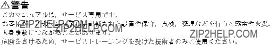
! WARNING
This manual is intended for qualified service personnel only.
To reduce the risk of electric shock, fire or injury, do not perform any servicing other than that contained in the operating instructions unless you are qualified to do so. Refer all servicing to qualified service personnel.
! WARNUNG
Die Anleitung ist nur f??r qualifiziertes Fachpersonal bestimmt.
Alle Wartungsarbeiten d??rfen nur von qualifiziertem Fachpersonal ausgef??hrt werden. Um die Gefahr eines elektrischen Schlages, Feuergefahr und Verletzungen zu vermeiden, sind bei Wartungsarbeiten strikt die Angaben in der Anleitung zu befolgen. Andere als die angegeben Wartungsarbeiten d??rfen nur von Personen ausgef??hrt werden, die eine spezielle Bef??higung dazu besitzen.
! AVERTISSEMENT
Ce manual est destin?? uniquement aux personnes comp??tentes en charge de l???entretien. Afin de r??duire les risques de d??charge ??lectrique, d???incendie ou de blessure n???effectuer que les r??parations indiqu??es dans le mode d???emploi ?? moins d?????tre qualifi?? pour en effectuer d???autres. Pour toute r??paration faire appel ?? une personne comp??tente uniquement.
Table of Contents
Manual Structure
3. Spare Parts
4.Semiconductor Pin Assignments
5.Block Diagram
6. Schematic Diagrams
7. Board Layouts
Manual Structure
Purpose of this manual
This manual is the maintenance manual of Analog Audio Distribution Board
This manual is intended for use by trained system and service engineers, and describes the information for periodic maintenance and detailed service.
Contents
This manual is organized by following sections.
Section 1 Service Overview
This section explains the notes on repair parts and IC link replacement.
Section 2 Electrical Alignment
This section explains the adjustment after replacing part.
Section 3 Spare Parts
This section describes the spare parts.
Section 4 Semiconductor Pin Assignments
This section describes the pin assignments of semiconductor.
Section 5 Block Diagram
This section describes the overall block diagram.
Section 6 Schematic Diagrams
This section describes the schematic diagrams of the
Section 7 Board Layouts
This section describes the board layouts for the
Related manuals
The following manual is prepared for this unit.
.Installation Manual (Supplied with
This manual describes the information on
Section 1
Service Overview
1.Safety Related Components Warning w
Components marked !are critical to safe operation. Therefore, specified parts should be used in the case of replacement.
2.Standardization of Parts
Some repair parts supplied by Sony differ from those used for the unit. These are because of parts common- ality and improvement.
Parts list has the present standardized repair parts.
3.Stock of Parts
Parts marked with ???o??? at SP (Supply code) column of the spare parts list may not be stocked. Therefore, the delivery date will be delayed.
4.Units Representation
The following represented units are changed or omitted in writing.
n
For the replacement of the
w
An IC link is critical parts to safe operation. Replace this component with Sony parts whose part numbers appear in this manual published by Sony. If not, this may cause a fire or electric shock.
Be sure to use the specified component in this manual.
The IC link is mounted on the
(S/N10001 through S/N17325)
The shield case is a component to shield the

Switches/shorting plugs (Factory default settings are indicated by a \mark)
Indicator
Gain adjusting VR
n
At the
Boards requiring use of unleaded solder are printed with a lead free mark (LF) indicating the solder contains no lead. (Caution: Some printed circuit boards may not come printed with the lead free mark due to their particular size.)
 : LEAD FREE MARK
m
.Be sure to use the unleaded solder for the printed circuit board printed with the lead free mark.
.The unleaded solder melts at a temperature about 40 dC higher than the ordinary solder, therefore, it is recom-
mended to use the soldering iron having a temperature regulator.
.The ordinary soldering iron can be used but the iron tip has to be applied to the solder joint for a slightly longer time. The printed pattern (copper foil) may peel away if the heated tip is applied for too long, so be careful.
Section 2
Electrical Alignment
Use the equipment listed below or the equivalent.
*: Use the equipment after calibration has been completed.
1.Extend the
2.Write the customer settings of the shorting plugs (COR1, COR2, and COR3) and switches (S1, and S2) on the
3.Set their shorting plugs and switches as follows:
4.Turn on the power of equipment (the signal generator, audio level meter, and interface unit
5.Attach the 600 Z resister for termination to the audio level meter.
Measuring equipment: Audio level meter
1.Set the output of the generator to +4.0 dBm, 1 kHz. (0 dBm = 0.775 Vrms)
CH1 adjustment
2.Connect the audio signal generator to the input of CH1 connector.
3.Connect the audio level meter to one output of CH1 connector.
4.Check that COR2
5.Adjust the CH1 output level on the audio level meter. Adjustment point:
CH2 adjustment
6.Connect the audio signal generator to the input of CH2 connector.
7.Connect the audio level meter to one output of CH2 connector.
8.Check that COR1
9.Adjust the CH2 output level on the audio level meter.
Adjustment point:
Specification: 4.0 ?? 0.1 dBm (at 600 Z load)

Ratio) Adjustment
Measuring equipment: Audio level meter
1. Set the output of the generator to +15.0 dBm, 60 Hz.
CH2 adjustment
2.Connect the audio signal generator to the input of CH2 connector.
3.Connect the audio level meter to one output of CH2 connector.
4.Adjust the CH2 output level on the audio level meter. Adjustment point:
CH1 adjustment
5.Connect the audio signal generator to the input of CH1 connector.
6.Connect the audio level meter to one output of CH1 connector.
7.Adjust the CH1 output level on the audio level meter.
Adjustment point:
Specification: Less than _65 dBm (at 600 Z load)
n
When the audio gain (COR1 or COR2) is not 0 dB, be sure to perform this adjustment.
Measuring equipment: Audio level meter
1.Reset the shorting plugs (COR1 and COR2) on the
CH1 adjustment
2.Set the output of the generator to the customer setting of COR1 as follows:
3.Connect the audio signal generator to the input of CH1 connector.
4.Connect the audio level meter to one output of CH1 connector.
5.Adjust the CH1 output level on the audio level meter. Adjustment point:
CH2 adjustment
6.Set the output of the generator to the customer setting of COR2. (Refer to table in step 2.)
7.Connect the audio signal generator to the input of CH2 connector.
8.Connect the audio level meter to one output of CH2 connector.
9.Adjust the CH2 output level on the audio level meter.
Adjustment point:
Specification: 4.0 ?? 0.1 dBm (at 600 Z load)
10.After turning off the power, reset the shorting plug (COR3) and switches (S1 and S2) on the
Section 3
Spare Parts

Index
Section 4
Semiconductor Pin Assignments

Diode, LED, Transistor
??? TOP VIEW???
UN2221
(R1=2.2k,R2=2.2k)
R1
R2
??? TOP VIEW???
2SC1623
IC
IC
??? TOP VIEW???
NJM5534M (JRC)
NJM5534M(TE2)
OPERATINAL AMPLIFIER
PCF8574AT (PHILIPS)
??? TOP VIEW???

Overall Overall
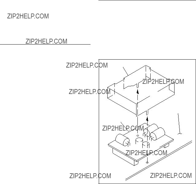
Section 5
Block Diagram
1 GAIN
OFF ON
MOTHERBOARD
S/N
Overall

Section 6
Schematic Diagrams
Index

SUFFIX:
COP2
1
2
3
4
5
TP11
TP12
C93 1uF
TP13
R132
TP14
R136
BOARD NO.

1
2
3
4
5
CN1(1/2)
TO/FROM
CN1(2/2)
BOARD NO.
LOT NO. 812-
1
GND
BOARD NO.
3
GND
BOARD NO.
5

1
CN3
1 +5Vin
2
7 GND
3
4
5
BOARD NO.
LOT NO.
SUFFIX:
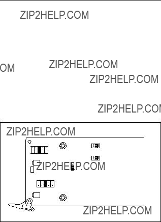
Section 7
Board Layouts
SUFFIX:
SUFFIX:
SUFFIX:
SUFFIX:

SUFFIX:
SUFFIX:
*:B SIDE