DIGITAL AUDIO MIXING CONSOLE
OPERATION MANUAL [English] 1st Edition (Revised 3) Software Version 3.0 and Later
DIGITAL AUDIO MIXING CONSOLE
OPERATION MANUAL [English] 1st Edition (Revised 3) Software Version 3.0 and Later

CAUTION
Installation has to be done by a SONY authorized technician.
WARNING
To prevent fire or shock hazard, do not expose the unit to rain or moisture.
To avoid electrical shock, do not open the cabinet. Refer servicing to qualified personnel only.
VORSICHT
Um Feuergefahr und die Gefahr eines elektrischen Schlages zu vermeiden, darf das Ger??t weder Regen noch Feuchtigkeit ausgesetzt werden.
Um einen elektrischen Schlag zu vermeiden, darf das Geh??use nicht ge??ffnet werden. ??berlassen Sie Wartungsarbeiten stets nur einem Fachmann.
For customers in the U.S.A
WARNING
This equipment has been tested and found to comply with the limits for a Class A digital device, pursuant to Part 15 of the FCC Rules. These limits are designed to provide reasonable protection against harmful interference when the equipment is operated in a commercial environment. This equipment generates, uses, and can radiate radio frequency energy and, if not installed and used in accordance with the instruction manual, may cause harmful interference to radio communications. Operation of this equipment in a residential area is likely to cause harmful interference in which case the user will be required to correct the interference at his own expense.
You are cautioned that any changes or modifications not expressly approved in this manual could void your authority to operate this equipment.
The shielded interface cable recommended in this manual must be used with this equipment in order to comply with the limits for a digital device pursuant to Subpart B of Part 15 of FCC rules.
presence of important operating and maintenance (servicing) instructions in the literature accompanying the appliance.
For customers in Europe
This product with CE marking complies with both the EMC Directive (89/336/EEC) and the Low Voltage Directive (73/23/EEC) issued by the Commission of the European Community.
Compliance with these directives implies conformity to the following European standards:
???EN60950 : Product Safety
???
???
This product is intended for use in the following Electromagnetic Environment(s)
E4 (controlled EMC environment, ex. TV studio)
Pour les clients europ??ens
Ce produit portant la marque CE est conforme ?? la fois ?? la Directive sur la compatibilit?? ??lectromagn??tique (EMC) (89/336/CEE) et ?? la Directive sur les basses tensions (73/23/CEE) ??mises par la Commission de la Communaut?? europ??enne.
La conformit?? ?? cas directives implique la conformti?? aux normes erop??ennes suivantes:
???EN60950 : S??curit?? des produits
???
???
Ce produit est pr??vu pour ??tre utilis?? dans les environments ??lectromagn??tiques suivants:
E4 (environment EMC contr??l?? ex. studio de t??l??vision).
F??r Kunden in Europa
Dieses Product besitzt die
Die Erf??llung dieser Directiven bedeutet Konformit??t f??r die folgenden Europ??ischen Normen:
??? EN60950 : Produktsicherheit
???
???
(Immunit??t)
Dies Produkt ist f??r den Einsatz unter folgenden electromagnetischen Bedingungen ausgelegt:
E4 (kontrollierter
Peak Inrush Current
(1)Power ON, current probe method:
50A (100V)
110A (240V)
(2)Hot switching inrush current, measured in accordance with European standard
40A (230V)
(1)Power ON, current probe method:
40A (100V)
80A (240V)
(2)Hot switching inrush current, measured in accordance with European standard
80A (230V)
(1)Power ON, current probe method:
20A (100V)
70A (240V)
(2)Hot switching inrush current, measured in accordance with European standard
30A (230V)
Appel de Courant de Cr??te
(1)Mise sous tension (ON), m??thode de sondage du courant:
50A (100V)
110A (240V)
(2)Mesur?? conform??ment ?? la norme europ??enne
40A (230V)
(1)Mise sous tension (ON), m??thode de sondage du courant:
40A (100V)
80A (240V)
(2)Mesur?? conform??ment ?? la norme europ??enne
80A (230V)
(1)Mise sous tension (ON), m??thode de sondage du courant:
20A (100)
70A (240V)
(2)Mesur?? conform??ment ?? la norme europ??enne
30A (230V)
Spitzenstrom
(1)Einschaltstrom, Stromsonde:
50A (100V)
110A (240V)
(2)Gemessen in
40A (230V)
(1)Einschaltstrom, Stromsonde:
40A (100V)
80A (240V)
(2)Gemessen in
80A (230V)
(1)Einschaltstrom, Stromsonde:
20A (100V)
70A (240V)
(2)Gemessen in
30A (230V)
i
WARNING
This unit has no power switch.
When installing the unit, incorporate a readily accessible disconnect device in the fixed wiring, or connect the power cord to a
If a fault should occur during operation of the unit, operate the disconnect device to switch the power supply off, or disconnect the power cord.
WARNUNG
Dieses Ger??t hat keinen Netzschalter.
Beim Einbau des Ger??ts ist daher im Festkabel ein leicht zug??nglicher Unterbrecher einzuf??gen, oder das Netzkabel mu?? mit einer in der N??he des Ger??ts befindlichen, leicht zug??nglichen Wandsteckdose verbunden werden.
Wenn w??hrend des Betriebs eine Funktionsst??rung auftritt, ist der Unterbrecher zu bet??tigen bzw, das Netzkabel abzuziehen, damit die Stromversorgung zum Ger??t unterbrochen wird.
WARNING: THIS WARNING IS APPLICABLE FOR
USA ONLY.
If used in USA, use the UL LISTED power cord specified below.
DO NOT USE ANY OTHER POWER CORD.
Using this unit at a voltage other than 120V may require the use of a different line cord or attachment plug, or both.
To reduce the risk of fire or electric shock, refer servicing to qualified service personnel.
ii

Table of Contents
Chapter 1
Overview
Chapter 2
Powering The
Chapter 3
Getting Started

Table of Contents
Chapter 4
Signal Paths
Chapter 5
Control Screens
Chapter 6
Technical Descriptions
2 Table of Contents

Chapter 6
Technical Descriptions
Chapter 7
Session Management???
(Continued)

Table of Contents
Chapter 7
Session Management???
Appendixes
4 Table of Contents

About This Manual
Purpose and intended readers
This is the operation manual for the
This manual is aimed at professionals such as operators and engineers working in
Model numbers covered by this manual
This manual refers in general terms to the
Organisation
This manual is divided into the following seven chapters and four appendixes:
Chapter 1 Overview
Introduces the features of the
Chapter 2 Powering the
Includes the system
Chapter 3 Getting Started
Gives an overview of the
Chapter 4 Signal Paths
Explains the general principles of building signal paths and gives examples of types of signal paths that may be built from the basic default signal path existing at
Chapter 5 Control Screens
Lists all the control screens available in the
Chapter 6 Technical Descriptions
Provides the descriptions of all the modules of the
Chapter 7 Session Management??? System
Describes the sophisticated and flexible Session Management??? system available to
Appendixes
Provide the information for the following:
???Software installation/upgrades
???
???Specifications
???Diagnostic facilities (There are no user operable diagnostic facilities provided in this version of the

About This Manual
Conventions used in this manual
This manual uses the following conventions:
Important note
6 About This Manual
Related manuals
In addition to this operation manual, the following manuals are available for the
???Installation Manual
???Service Manual

Glossary of Terms
8 Glossary of Terms

Chapter 1 ??? Overview
This chapter introduces the
Chapter 1 Contents
Overview 1 Chapter
Chapter 1 Overview
Overview 1 Chapter
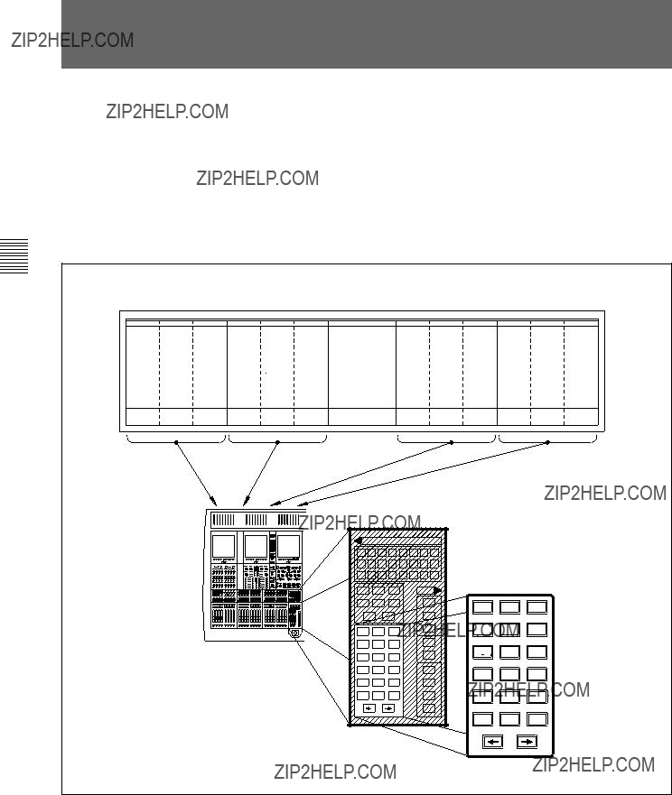
The
???Control Console with Modular Control Surface
???Host Computer
???Signal Processing (SP) Rack
???Digital and Analogue I/O Racks
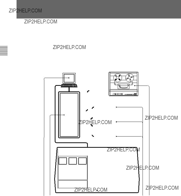
The following illustration shows a basic system concept diagram.

Control Console
Compared with traditional console designs, the
Modular Control Surface
The control surface of the
Signal Processing (SP) Rack
The SP rack is designed to use the minimum number of signal processing cards depending on the system size. A high level Software Design Tools System is used to generate automatically the low level software microcode which runs the SP system. Data links to and from the control console are via Ethernet connections, whilst a MADI interface is used between the SP rack and the I/O racks. Additional bandwidth, available within the MADI signal, is used to pass data for purposes such as remote control of analogue amplifier gain.
Digital and Analogue I/O Racks
The I/O racks are designed to be located close to the equipment with which they interface. Each I/O rack can contain a mix of up to 56 high quality analogue inputs and/or outputs on 10 analogue I/O cards. Each analogue card handles 4 or 8 inputs and 4 or 8 outputs according to its type. A mix of input and output cards in the same I/O rack may, for example, allow cue outputs for headphones to be local to appropriate microphone sources.
The digital and analogue I/O are housed in a single rack type. Digital I/O has the same capability as the analogue, of up to 56 inputs and 56 outputs per rack via AES/EBU and
Machine Control
Machine control for the
Note:
Refer to the Appendixes in this manual for further details of
Overview 1 Chapter
Chapter 1 Overview

Sample installation illustrating Audio & Control Data flow
1 Control Room
2 Rack Room
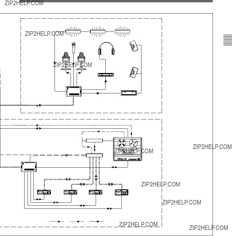
3 Studio
4 Machine Room
Chapter 1 Overview


MAIN OUTPUT BUS - STEREO, LCRS, 5.1 or 7.1
16 SUPER SEND GROUPS - MONO, STEREO, LCR, LCRS, 5.0, 5.1, 7.0 & 7.1
48 MULTITRACK BUSSES - Up to 8
CUE & AUXILIARY SENDS
Chapter1Overview
Chapter 2 ??? Powering The
This chapter provides
Chapter 2 Contents
Chapter 2 Powering the

CAUTIONS:
1.Before
2.Switch on equipment in the sequence given here, to ensure trouble- free
1.Check that the motionworker and Lynx Time Code Module are already switched on and running normally.
2.Switch on the power to the SP Rack.
3.Switch on the power to the Host Computer.
4.Switch on the power to the I/O Racks.
Note:
It is important that the I/O racks are switched on in the sequence of the Sync
Clock wiring loop connected to the clock inputs of the I/O Racks.
5.The Host Computer performs its
6.Type b then press {RETURN} to start the
Note:
If your Host Computer has been configured for
7.At the end of the
8.Now switch on the power to the control panel. All 7 LCD screens will show activity as programs are downloaded from the Host Computer to the computers within the console. When downloading is completed, an ???X??? is displayed in the centre of each screen.

9.Log in at the Host Computer. Note that the user name and password below are the system defaults.
Type sm
Type in the password:
Notes:
1
2Login can be initiated while programs are still being downloaded from the Host Computer. It is not necessary to wait until all the console LCD screens are displaying ???X??? in their centres.
10.Once
11.Check that the console LCD screens are all displaying ???X??? before proceeding, then:
Type: run_r3
12.Observe that the centre LCD screen in the console displays a summary of the processes being executed by the Host Computer which are displayed in greater detail on the monitor.
13.When the loading of the Netlist is complete, the centre screen of the console displays the
14.
Chapter 2 Powering the

CAUTION:
Turn off or mute all monitor amplifiers connected to the
Unless the
1.At the centre LCD screen on the
Note:
If necessary, retrace a number of steps through the screens hierarchy to reach this point. Refer to the Screens Structure diagram in Chapter 5 for detailed information on the screen page hierarchy.
2.On the SYSTEM screen page, click on SYSTEM SHUTDOWN on the right side of the screen if it is displayed.
3.If SHUTDOWN is not displayed click on the ???User field??? for a
4.The console now shuts down and power to the control surface can be turned off but the STIF and UNIX windows on the Host Computer monitor remain.
5.On the Host Computer, place the mouse cursor in the STIF window and
Type: exit
Note:
It is important to switch off the power to the control surface for a minimum of 10 seconds before attempting a
6.For a

7.To shut down the Host Computer, place the cursor in the UNIX window, and
Type: su
{RETURN}.
8.At the ???password??? prompt:
Type the superuser password,
9.At the prompt which follows:
Type: shutdown
10.Wait for the >>> prompt to appear before powering down the Host Computer, SP and I/O Racks.
Chapter 2 Powering the

Chapter 3 ??? Getting Started
This chapter gives an overview of the control surface layout and functionality. It also provides easy to follow,
Chapter 3 Contents
Started Getting 3 Chapter
Chapter 3 Getting Started
Started Getting 3 Chapter
The

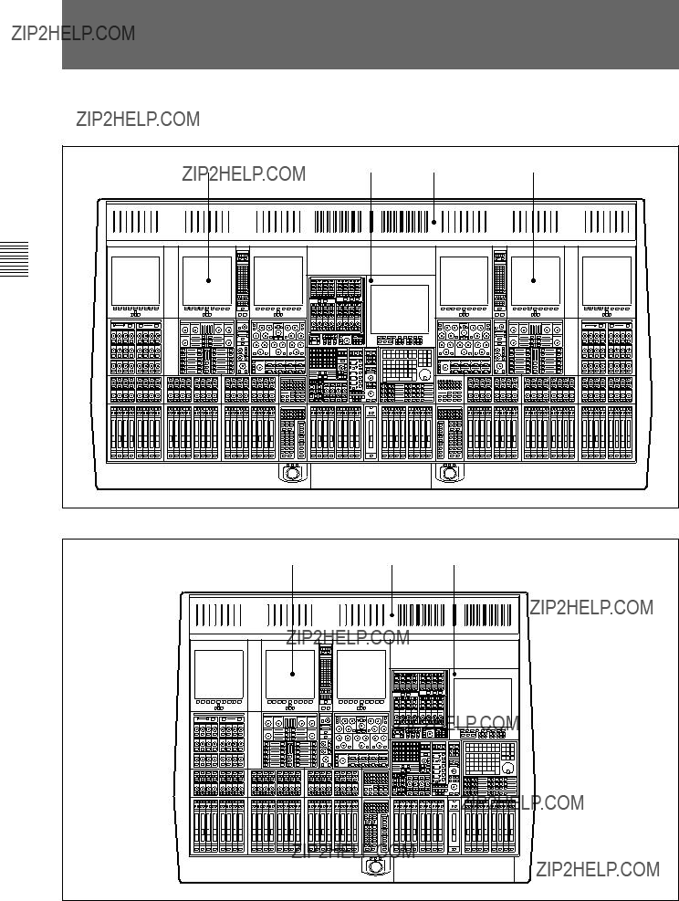
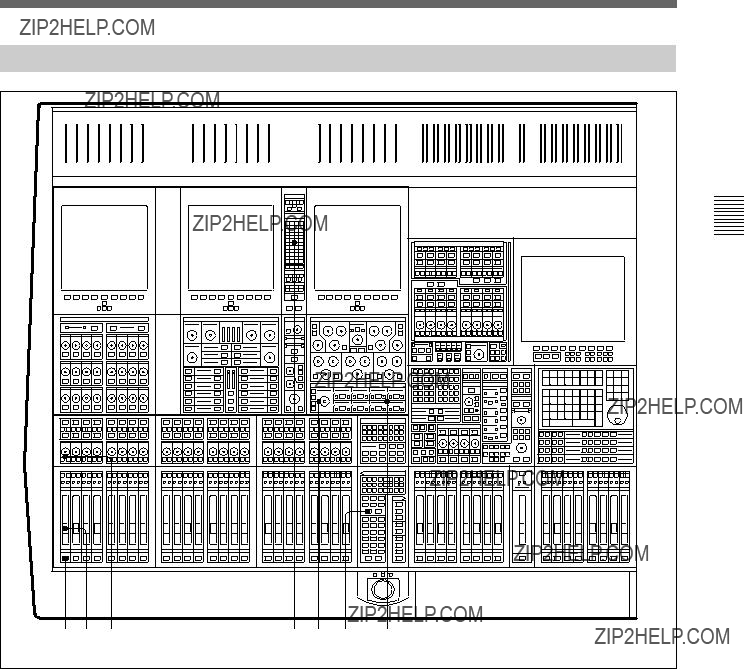
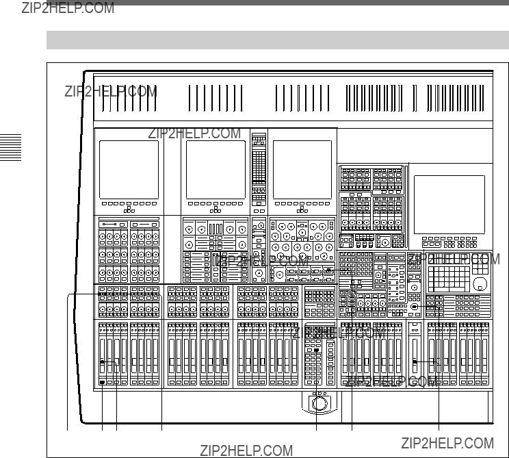
Control Surface Elements
1 Left hand 24 Fader Channels Section
2 Central Master Section
3 Right hand 24 Fader Channels Section
4 Meter Bridge
The Control Surface in general
A key feature of the
???INPUT CHANNEL, EQUALISER and FILTERS
???FREE ASSIGN AREA & DYNAMICS
???MULTITRACK, ROUTING for MULTITRACK, SUPER SEND GROUPS and
???SENDS (For Foldback and Effects feeds)
The channel section panel areas are mirrored so that every function can be operated from either side of the console, allowing two operators to work on the same channels simultaneously. The ability to have 48 channel faders and their related functions on view at all times is an advantage but everything can be operated from just one 24 fader channel bank and the centre section, as in the more compact
Use the following two diagrams for reference to identify each area as it is explained whilst reading through this manual.
Operation of the control surface can be split into 5 main areas:
1.USE OF FADER PAGING
2.USING ASSIGNABLE SIGNAL PROCESSING
3.SELECT TO FADERS FUNCTIONS
4.SELECT TO PANS FUNCTIONS
5.BUILDING SIGNAL PATHS
(Described in detail in Chapter 4)
Started Getting 3 Chapter
Chapter 3 Getting Started

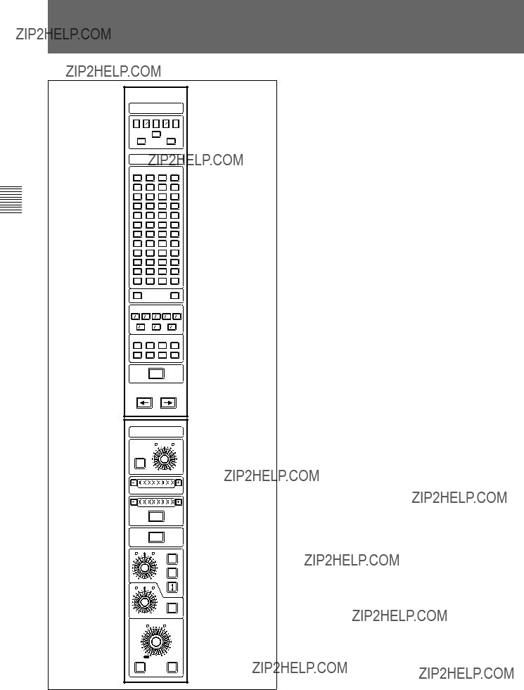
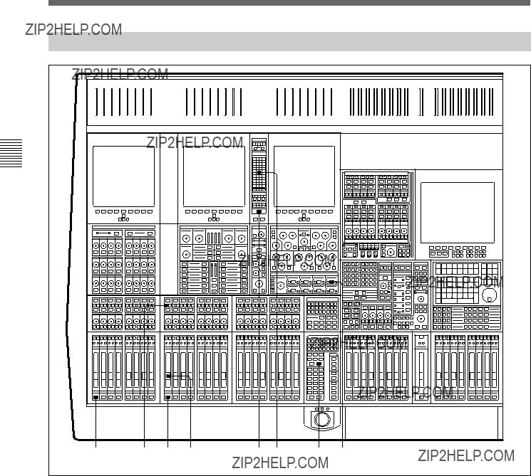
1Left hand assignable channel controls
2Right hand assignable channel controls
2
3 Chapter
Started Getting
Chapter 3 Getting Started

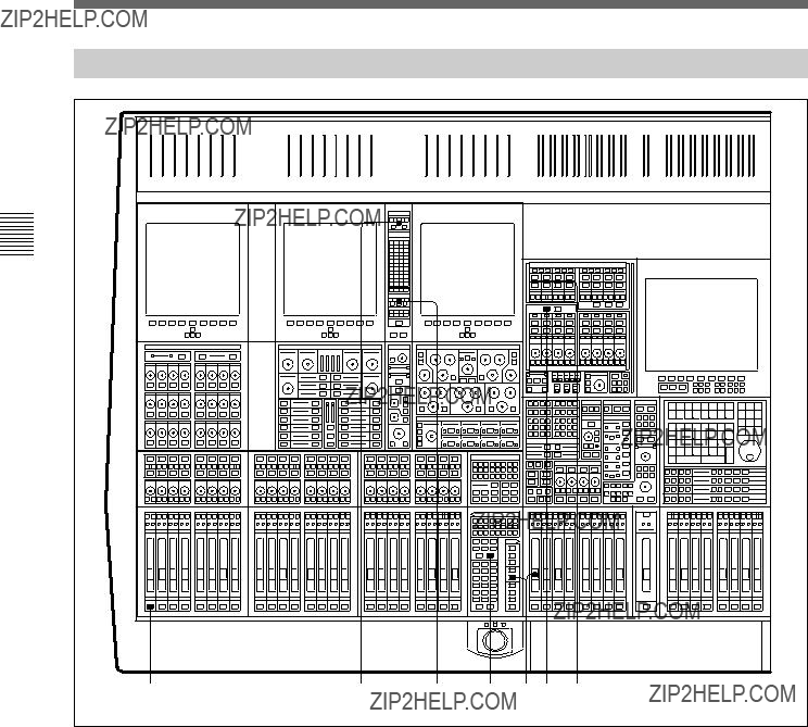
Started Getting 3 Chapter
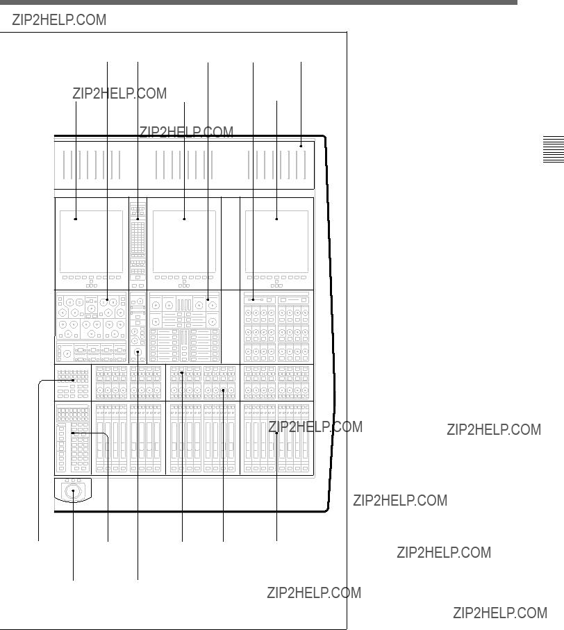
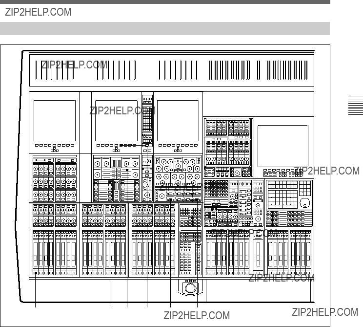
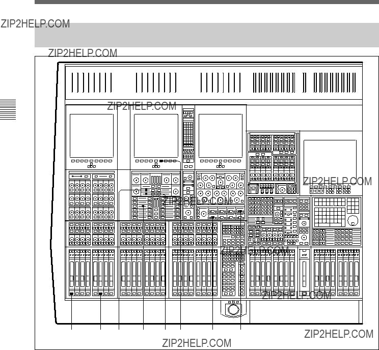
1 Meter Bridge ??? Mono Meters
2 Meter Bridge ??? Stereo Meters
3 Channel Screens (6)
4 Routing Panels
5
6 Super Send Group Masters
7 Sends Masters
8 Central Control Screen
9 Sends Panels
0Free Assign Area/Dynamics Panels
! ??Input & Equaliser Panels
!??? Multitrack Panels
!?? Track Monitoring Controls
!?? Assignable Pan Knobs
!??? Select to Pans Panels
!?? Monitor & Foldback Panel
!?? Control Keyboard & Automation Controls
!???Assignable Channel Faders
!??Select to Faders Panels
@??
@?? Main Output Fader
???@ Trackerballs
@?? QWERTY Keyboard (beneath
sliding cover)
Started Getting 3 Chapter
Chapter 3 Getting Started
Started Getting 3 Chapter
The
Paging of Faders for the left side of the control surface

Once the appropriate bank of 24 channel faders is selected, individual channel controls can be adjusted. To do this, press the ACCESS button below the fader for the channel required. Then all the ASSIGNABLE PANELS belong to the channel, displaying its settings. Adjust as necessary.
As can be seen from the diagram, the functions on an
Assignable panels
Started Getting 3 Chapter
Chapter 3 Getting Started

Started Getting 3 Chapter
The Input Channel section is much more flexible than a conventional in- line analogue channel strip in that it allows processing elements to be configured in almost any order. The eight boxes towards the bottom of the panel enable up to eight functions to be placed in each channel path with individual IN switches. The order of the processes can be totally different on every channel, as desired.
The 5 Band Equaliser and High & Low Filters sections are independent and can be assigned separately within the channel signal path. To view parameters and curves whenever EQ and Filters are in use, access the EQ page available on the channel screens.
Various EQ options are available which are selected using the { IN } and { + } / { - } buttons situated in the upper middle section of the panel.
Input Channel & Inserts, Equaliser and Filters panel

Free Assign Area & Dynamics panel
The Dynamics function area (lower left) contains:
???GATE
???EXPANDER
???COMPRESSOR (there are a number of Compressor options)
???LIMITER
???
Each section of the Dynamics has its own
???in the Dynamics
???in the Signal Path only as a second EQ
???in the Signal Path and the
The current Free Assign Area (lower right) contains:
??? DELAY Effect
This area includes space for additional effects as and when software upgrades are introduced in the future.
Started Getting 3 Chapter
Chapter 3 Getting Started
Groups and
Routing for Multitrack, Super Send Groups &
These routing buttons have a layout matching a set of 7.1 surround LS. Their function depends on what is selected to the faders at the SELECT TO FADERS panel. In other words, they set the destinations for the signals currently passing through the faders.
ROUTING Buttons
Two sets of buttons on each side of the console allow channel sources to be assigned to Multitrack Group Busses
SSGs
These buttons allow post channel fader and pan feeds to Super Send Groups
STEM Selectors { A } - { H }
These buttons are operational in
{BOUNCE}
Redirects the output of a channel from the Main Output Bus to the multitrack routing buttons in the MULTITRACK section for
MULTITRACK
This panel contains controls related to the multitrack except individual track remotes and monitor switching. These are above the pan controls in line with their equivalent number channel faders. All level controls can be assigned to faders. Surround panning is available at this panel in parallel with the joysticks and individual pans above the faders. These pan controls are operational on what is selected to the faders at the SELECT TO FADERS panel.
The

There are currently 24 mono Sends that can be linked as odd/even pairs, set up at the SEND OUTPUTS
Started Getting 3 Chapter
Chapter 3 Getting Started

Started Getting 3 Chapter
The main purpose of faders on a mixing console is to control the levels of the signals through the channels. Once a balance is achieved, the fader positions give an extremely useful graphical representation.
It is common with
Select to Faders
As an example, on the SELECT TO FADERS panels, adjacent to the channel faders on either side of the centre section, there are buttons marked:
1 {CHANS}
2 {M/T SEND}
The default is {CHANS} , which assigns the faders to the channel outputs when they control the level to the Main Output Bus. Selecting M/T SEND is equivalent to selecting the ???small fader??? function to the
Select To Faders panel layout
Started Getting 3 Chapter
Chapter 3 Getting Started

Started Getting 3 Chapter
Exploiting this approach even further, the faders can also be assigned to control Input Gain, Group Trim and all Send Bus levels.
The Select to Faders diagram at the beginning of this section is a visual guide showing how the
This approach is very convenient for checking foldback or effects send balances. The faders and their selector system are very close at hand, allowing any balance to be quickly checked at a glance and adjusted.
A copy function allows the user to take the balance
This is described in detail in Chapter 6.
The 16 centre section master faders are also assignable in two groups of 8 faders. They are assigned via the SEL area on the SELECT TO FADERS panel and may control:
???SENDs (Send Master levels)
???SUPER SGs (Super Send Group master levels)
???GROUPs (VCA style control group masters)

The Pan Knobs above the faders are assignable in a similar manner to the faders. Although their primary job is panning, they can also be used to perform all channel level adjustments, such as input gain settings and Send Bus levels. They are really Definable Knobs rather than just Pans.
As can be seen in the diagram below, the SELECT TO PANS panel performs a function for the Pans similar to that of the SELECT TO FADERS panel for the faders. All equivalent level and gain control functions, on an
A typical
Select to Pans
Started Getting 3 Chapter
Chapter 3 Getting Started

Started Getting 3 Chapter
General
The following series of illustrations and brief step by step procedures are designed to allow new
System
The examples shown assume that signal sources, such as microphones, line level signals and multitrack or hard disc recorder, are already connected and routed to appropriate inputs, with machine control in place. They also assume that the control room monitor LS are hooked up to the
Main Bus
The Main Output Bus can be set for the following ???widths???: Stereo, LCRS, 5.1 and 7.1. For the purposes of the examples, the

Started Getting 3 Chapter
1 Press {ACCESS} for the desired Channel.
2 At the Input Channel & Inserts panel, press either {MIC} or {LINE} as required, and set the input GAIN knob to a suitable setting.
3 Make sure {CHANS} is selected on the Select To Faders panel
4 At the Routing panel, select { L } and { R }
5 Adjust the level to the Main Output Bus with the Channel Fader.
6 Open the Main Fader and turn up the CR Monitor level.
Chapter 3 Getting Started
Started Getting 3 Chapter
6 At the Select To Faders panel (SEL section), select {SUPER SGs
7 Above the SSG 1 level knob select {MAIN} and its
{ACCESS} .
8 At the top of the Routing panel select { L } .
9 Repeat steps 7 and 8 for SSG 2 but select { R } at the Routing panel.
10 Repeat steps 1 to 5 for further channels.
Started Getting 3 Chapter
Chapter 3 Getting Started
Started Getting 3 Chapter

Started Getting 3 Chapter
1 At the Send Outputs
Note:
Send Masters 19 and 20 are assigned to Stereo Foldback O/P 2; 21 and 22 to Foldback 3; 23 and 24 to Foldback 4.
2 At the Select To Faders panel, select {SEND 17} or {SEND 18} . Pressing either will light both.
3 Turn off the {CUT} buttons and set up the balance and pan positions using the Faders and their Pans. Turn off the Pan {CUT} if necessary.
4 At the Foldback Groups
5 The bus level itself, which defaults to unity gain, can be adjusted using the central faders. On the Select To Faders panel, SEL section, select {SENDs
Chapter 3 Getting Started

Started Getting 3 Chapter
1 Press {ACCESS} for the desired Channel.
2 At the Input Channel & Inserts panel, select ???MULTI??? in window number 4 using the { + } and { ??? } buttons either side. Select its large { IN } button to insert the multitrack into the signal path.
3 At the same panel, select ???EQ??? in a window before window 4, window 1 for example, and select the large { IN } button to insert the equaliser into the signal path before the multitrack.
4 On the upper section of the same panel, select the individual { IN } buttons for the bands required and adjust as necessary.
5 Select the EQ softkey for the screen above the equaliser panel to view the parameters and response curve graph.
Started Getting 3 Chapter
1 Press {ACCESS} for the desired Channel.
2 At the Input Channel & Inserts panel, select ???MULTI??? in window number 5 using the { + } and { ??? } buttons either side. Select its large { IN } button to insert the multitrack into the signal path.
3 At the same panel, select ???EQ??? in a window after window 5, window 8 for example, and select the large { IN } button to insert the equaliser into the signal path after the multitrack.
4 On the upper section of the same panel, select the individual { IN } buttons for the bands required and adjust as necessary.
5 Select the EQ softkey for the screen above the equaliser panel to view the parameters and response curve graph.
Chapter 3 Getting Started

Started Getting 3 Chapter
required: Gate, Compressor, etc., indicated by 8 character dot displays.
5 On the LCD screen above the dynamics controls, press the Dynamics softkey to view the parameters and transfer curve graph.
6 The dynamics processing is set and displayed via definable knobs and switches. Set their functions via the local {ACCESS} keys according to the processes in use. Adjust whilst viewing the settings on the LCD screen. The settings for all functions are displayed simultaneously.
Started Getting 3 Chapter
required: Gate, Compressor, etc., indicated by 8 character dot displays.
5 On the LCD screen above the dynamics controls, press the Dynamics softkey to see the parameters and transfer curve graph.
6 The dynamics processing is set and displayed via definable knobs and switches. Set their functions via the local {ACCESS} keys according to the processes in use. Adjust whilst viewing the settings on the LCD screen. The settings for all functions are displayed simultaneously.
Chapter 3 Getting Started
Started Getting 3 Chapter

Started Getting 3 Chapter
6 At the Select To Faders panel (SEL section), select {SUPER SGs
7 Above the SSG 1 level knob select {MAIN} and its
{ACCESS} .
8 At the top of the Routing panel select { L } .
9 Repeat steps 7 and 8 for SSG 2 but select { R } at the Routing panel.
10 Repeat steps 1 to 5 for further channels.
Chapter 3 Getting Started

Started Getting 3 Chapter
5 Now
6 At the same panel, select COMPRESS { IN } . The Compressor {ACCESS} will be selected automatically, allowing the compressor to be set.
7 Select the Dynamics softkey to view compressor parameters and transfer curve graph on the LCD screen.

Started Getting 3 Chapter
1 Press {ACCESS} for the first Channel to have a dynamics
2 At the Input Channel & Inserts panel, select ???DYN??? in one of the eight windows. Do this using the { + } and { ??? } buttons, and then press the large { IN } button.
3 At the Free Assign Area & Dynamics section, select the COMPRESS { IN } . Its {ACCESS} will be selected automatically, assigning the Compressor controls to the panel for adjustment.
4 On the LCD screen above the dynamics controls, press the Dynamics softkey to view the parameters and transfer curve graph.
5 Select SC TO G1 in the middle window.
6 Select SC FM G1 in the lower window.
7 Repeat Steps 1 to 4 for further channels required in the
Chapter 3 Getting Started
Started Getting 3 Chapter
1 Press the {ACCESS} button for the controlling Channel.
2 At the Input Channel & Inserts panel, select ???DYN??? in one of the eight windows. Do this using the { + } and { ??? } buttons, and then press the large { IN } button.
3 At the Free Assign Area & Dynamics section, select the COMPRESS { IN } . Its {ACCESS} will be selected automatically, assigning the Compressor controls to the panel for adjustment.

8 At the Free Assign Area & Dynamics section, select SC FM G1 in the lower window.
9 All adjustments are made on the first channel.
Started Getting 3 Chapter
Chapter 3 Getting Started