LCD Monitor
Instructions for Use
Before operating the unit, please read this manual thoroughly and retain it for future reference.
?? 2008 Sony Corporation
LCD Monitor
Instructions for Use
Before operating the unit, please read this manual thoroughly and retain it for future reference.
?? 2008 Sony Corporation

Owner???s Record
The model and serial numbers are located at the rear. Record these numbers in the spaces provided below. Refer to these numbers whenever you call upon your Sony dealer regarding this product.
Model No. ____________________
Serial No. ____________________
WARNING
To reduce the risk of fire or electric shock, do not expose this apparatus to rain or moisture.
To avoid electrical shock, do not open the cabinet. Refer servicing to qualified personnel only.
WARNING
THIS APPARATUS MUST BE EARTHED.
To disconnect the main power, unplug the AC plug.
For the customers in Canada
This unit has been certified according to Standard CSA C22.2 No.601.1
For the customers in the U.S.A.
This equipment has been tested and found to comply with the limits for a Class A digital device, pursuant to Part 15 of the FCC Rules. These limits are designed to provide reasonable protection against harmful interference when the equipment is operated in a commercial environment. This equipment generates, uses, and can radiate radio frequency energy and, if not installed and used in accordance with the instruction manual, may cause harmful interference to radio communications. Operation of this equipment in a residential area is likely to cause harmful interference in which case the user will be required to correct the interference at his own expense.
You are cautioned that any changes or modifications not expressly approved in this manual could void your authority to operate this equipment.
All interface cables used to connect peripherals must be shielded in order to comply with the limits for a digital device pursuant to Subpart B of Part 15 of FCC Rules.
WARNING:
Using this unit at a voltage other than 120 V may require the use of a different line cord or attachment plug, or both. To reduce the risk of fire or electric shock, refer servicing to qualified service personnel.
For the customers in the U.S.A and Canada
When you use this product connected to 240 V single phase, be sure to connect this product to a center tapped circuit.
Important safeguards/notices for use in the medical environments
1.All the equipments connected to this unit shall be certified according to Standard
2.Furthermore all configurations shall comply with the system standard
Everybody who connects additional equipment to the signal input part or signal output part configures a medical system, and is therefore, responsible that the system complies with the requirements of the system standard
If in doubt, consult the qualified service personnel.
3.The leakage current could increase when connected to other equipment.
4.For this particular equipment, all accessory equipment connected as noted above, must be connected to mains via an additional isolation transformer conforming with the construction requirements of
5.This equipment generates, uses, and can radiate radio frequency energy. If it is not installed and used in accordance with the instruction manual, it may cause interference to other equipment. If this unit causes interference (which can be determined by unplugging the power cord from the unit), try these measures: Relocate the unit with respect to the susceptible equipment. Plug this unit and the susceptible equipment into different branch circuit.
Consult your dealer. (According to standard
6.Model
WARNING
When installing the unit, incorporate a readily accessible disconnect device in the fixed wiring, or connect the power plug to an easily accessible socket- outlet near the unit. If a fault should occur during operation of the unit, operate the disconnect device to switch the power supply off, or disconnect the power plug.
2
Caution
When you dispose of the unit or accessories, you must obey the law in the relative area or country and the regulation in the relative hospital.
For the customers in the USA
Lamp in this product contains mercury. Disposal of these materials may be regulated due to environmental considerations. For disposal or recycling information, please contact your local authorities or the Electronic Industries Alliance (www.eiae.org).
WARNING on power connection
Use a proper power cord for your local power supply.
1.Use the approved Power Cord
2.Use the Power Cord
If you have questions on the use of the above Power Cord / Appliance Connector / Plug, please consult a qualified service personnel.
WARNING on power connection for medical use
Please use the following power supply cord. With connectors (plug or female) and cord types other than those indicated in this table, use the power supply cord that is approved for use in your area.
*Note: Grounding reliability can only be achieved when the equipment is connected to an equivalent receptacle marked ???Hospital Only??? or ???Hospital Grade???.
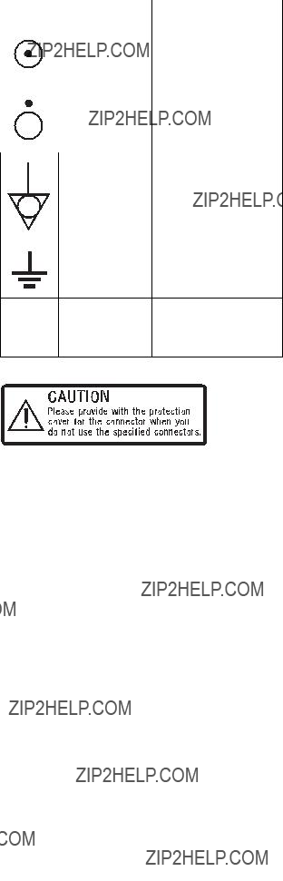
Symbols on the unit
This label is located on the rear panel of the unit.
See page 18 of these instructions for details about how to attach the connector covers.
3

Important EMC notices for use in the medical environments
???The
???The portable and mobile RF communications equipment such as cellular phones can affect the
Warning
The use of accessories and cables other than those specified, with the exception of replacement parts sold by Sony Corporation, may result in increased emissions or decreased immunity of the
Guidance and manufacturer???s
The
The customer or the user of the
Warning
If the
4

Guidance and manufacturer???s declaration - electromagnetic immunity
The
IEC
NOTE: UT is the a.c. mains voltage prior to application of the test level.
5

Guidance and manufacturer???s declaration - electromagnetic immunity
The
NOTE 1: At 80 MHz and 800 MHz, the higher frequency range applies.
NOTE 2: These guidelines may not apply in all situations. Electromagnetic propagation is affected by absorption and reflection from structures, objects and people.
aField strengths from fixed transmitters, such as base stations for radio (cellular/cordless) telephones and land mobile radios, amateur radio, AM and FM radio broadcast and TV broadcast cannot be predicted theoretically with accuracy. To assess the electromagnetic environment due to fixed RF transmitters, an electromagnetic site survey should be considered. If the measured field strength in the location in which the
bOver the frequency range 150 kHz to 80 MHz, field strengths should be less than 3 V/m.
6

Recommended separation distances between portable and mobile RF communications equipment and the LMD- 3250MD
The
For transmitters rated a maximum output power not listed above, the recommended separation distance d in meters (m) can be estimated using the equation applicable to the frequency of the transmitter, where P is the maximum output power rating of the transmitter in watts (W) according to the transmitter manufacturer.
NOTE 1: At 80 MHz and 800 MHz, the separation distance for the higher frequency range applies.
NOTE 2: These guidelines may not apply in all situations. Electromagnetic propagation is affected by absorption and reflection from structures, objects and people.
7

8 Table of Contents

Precaution
On Safety
???Operate the unit on
???The nameplate indicating operating voltage, etc. is located on the AC adaptor.
???Should any solid object or liquid fall into the cabinet, unplug the unit and have it checked by qualified personnel before operating it any further.
???Unplug the unit from the wall outlet if it is not to be used for several days or more.
???To disconnect the AC power cord, pull it out by grasping the plug. Never pull the cord itself.
???The
On Installation
???Prevent internal heat
Do not place the unit on surfaces (rugs, blankets, etc.) or near materials (curtains, draperies) that may block the ventilation holes.
???Do not install the unit near heat sources such as radiators or air ducts, or in a place subject to direct sunlight, excessive dust, mechanical vibration or shock.
???Do not place the monitor near equipment which generates magnetism, such as a transformer or high voltage power lines.
About the LCD Display Panel
???The LCD panel fitted to this unit is manufactured with high precision technology, giving a functioning pixel ratio of at least 99.99%. Thus a very small proportion of pixels may be ???stuck???, either always off (black), always on (red, green, or blue), or flashing. In addition, over a long period of use, because of the physical characteristics of the liquid crystal display, such ???stuck??? pixels may appear spontaneously. These problems are not a malfunction.
???Do not leave the LCD screen facing the sun as it can damage the LCD screen. Take care when you place the unit by a window.
???Do not push or scratch the LCD monitor???s screen. Do not place a heavy object on the LCD monitor???s screen. This may cause the screen to lose uniformity.
???If the unit is used in a cold place, a residual image may appear on the screen. This is not a malfunction. When
the monitor becomes warm, the screen returns to normal.
???If a fixed picture such as a frame of a divided picture or time code, or a still picture is displayed for a long time, an image may remain on the screen and be superimposed as a ghosting image.
???The screen and the cabinet become warm during operation. This is not a malfunction.
About the Fluorescent Tube
A specially designed fluorescent tube is installed as the lighting apparatus for this unit. If the LCD screen becomes dark, unstable or does not turn on, consult your Sony dealer.
On Cleaning
Before cleaning
Be sure to disconnect the AC power cord from the AC outlet.
On cleaning the monitor
A material that withstands disinfection is used for the front protection plate of the medical use LCD monitor. The protection plate surface is especially treated to reduce reflection of light. When solvents such as benzene or thinner, or acid, alkaline or abrasive detergent, or chemical cleaning cloth are used for the protection plate surface/monitor surface, the performance of the monitor may be impaired or the finish of the surface may be damaged. Take care with respect to the following:
???Clean the protection plate surface/monitor surface with a 50 to 70 v/v% concentration of isopropyl alcohol or a 76.9 to 81.4 v/v% concentration of ethanol using a swab method. Wipe the protection plate surface gently (wipe using less than 1 N force).
???Stubborn stains may be removed with a soft cloth such as a cleaning cloth lightly dampened with mild detergent solution using a swab method and then clean using the above chemical solution.
Never use solvents such as benzene or thinner, or acid, alkaline or abrasive detergent, or chemical cleaning cloth for cleaning or disinfection, as they will damage the protection plate surface/monitor surface.
???Do not use unnecessary force to rub the protection plate surface/monitor surface with a stained cloth. The protection plate surface/monitor surface may be scratched.
???Do not keep the protection plate surface/monitor surface in contact with a rubber or vinyl resin product for a long period of time. The finish of the surface may deteriorate or the coating may come off.
Precaution 9

Disposal of the Unit
???Do not dispose of the unit with general waste. Do not include the monitor with household waste.
???The fluorescent tube includes mercury. Dispose of the monitor in accordance with the regulations of your local sanitation authority.
Recommendation to Use more than One Unit
As problems can occasionally occur for the monitor, when the monitor is used for safety control of personnel, assets or stable picture, or for emergencies, we strongly recommend you use more than one unit or prepare a spare unit.
On Repacking
Do not throw away the carton and packing materials. They make an ideal container which to transport the unit.
If you have any questions about this unit, contact your authorized Sony dealer.
On Fan Error
The fan for cooling the unit is built in. When the fan stops and the RETURN button on the front panel blinks for fan error indication, turn off the power and contact an authorized Sony dealer.
On Moisture Condensation
If the unit is brought directly from a cold place to a warm place, or the unit is warm and the ambient temperature cools suddenly (by
Leave the unit in a condensation free area.
If moisture condensation has occurred, turn off the unit and do not use it until moisture condensation has evaporated.
Features
Compliance with medical safety standards in America, Canada and Europe
The monitor is designed for use in the medical treatment field, with the sheet switch, screen protect panel, etc.
Picture
Fully digital
As well as digital signals, all signals including analog signals are converted into digital signals. All signals are processed using a fully digital
Two color system available
The monitor can display NTSC and PAL signals by connecting this unit.
Auto chroma/phase function
The chroma and phase of the decoder are automatically adjusted with the auto chroma phase function.
High
A Full HD
Because a color filter with
Input
Accepts analog RGB input signals *1
Adopting the scan converter allows this monitor to detect VGA, SVGA, XGA and SXGA analog RGB signals input to the HD15 input connector.
10 Features
Accepts
Adopting the scan converter allows this monitor to detect VGA, SVGA, XGA and SXGA digital computer signals input to the DVI input connector.
To view SXGA signals when the DVI input is selected, use the cable within 3 m (118 1/8 inches) in length.
*1 For acceptable formats, see ???About the preset signal??? on page 35.
Optional slot for the video signal
One optional input adaptor can be attached. The composite, Y/C, component, analog RGB or SDI signal can be input depending on the input connectors of the board to be used.
NTSC or PAL color system or DTV format, such as 720P, 1080i, etc. can be selected automatically.
*2 For acceptable formats, see ???Available signal formats??? on page 34.
External sync input
The unit can be operated on the sync signal supplied from an external sync generator.
Functions
APA (Auto Pixel Alignment) function
You can display pictures from the HD15 input connector in the appropriate picture by simply pressing the APA key.
Automatic termination (connector with  mark only)
The input connector is terminated internally at 75 ohms when nothing has been connected to the output connector. If a cable is connected to the output connector, the internal terminal is automatically released and the signals input to the input connector are output to the output connector
Select color temperature and gamma mode
You can select the color temperature from among three (HIGH, LOW, LOW2) settings and gamma mode from between two settings (2.2, DICOM). You can also adjust the color temperature to the appropriate setting in ???USER???.
Two kinds of input signals are put on the monitor.
For more information, see MULTI DISPLAY of ???MULTI DISPLAY SETTING??? on page 28.
Color space feature
You can select
Aspect setting
You can set the monitor to 4:3 or 16:9 display mode according to the input signal.
Scan function
You can select the display from among ???NORMAL???, ???OVER??? and ???NATIVE??? (720P only) except the HD15 and DVI input signals.
Select language display
You can select your language for the display from seven languages - English, French, German, Spanish, Italian, Japanese and Chinese.
Power saving function
The monitor enters into power saving mode to reduce the power consumption when no signal is input.
Key inhibit function
You can inhibit the key to prevent missing an operation.
User memory function
You can save the 20 picture settings with the name. The user memory data can be saved or loaded between the monitor and the equipment (PC, etc.) connected in serial remote mode.
Two kinds of ground terminals
Two kinds of ground terminals are built into the monitor to equal the electric potential.
External remote function
The input signal is selected or various items are adjusted by use of the serial (Ethernet) remote function. You can connect this unit to the monitor by the Ethernet
For more information, see SERIAL REMOTE of REMOTE menu on page 30.
Other
Optional stand
It is more convenient to install the monitor on a desk by using the optional stand
Features 11

Location and Function of Parts and Controls
Front Panel
COMPOSITE
Y/C
RGB
COMPONENT
0
a Tally lamp
You can check the status of the monitor by the color of the tally lamp.
The tally lamp lights in green according to the setting of PARALLEL REMOTE in the REMOTE menu.
b Power indicator
When the power is turned on, the power indicator light in green.
c
Lights in white when KEY INHIBIT in the KEY INHIBIT menu is set to ON.
d CONTROL button
Press to display the buttons on the front panel. Press again to clear the display.
e CONTRAST buttons
Adjusts the picture contrast.
Press the + button to make the contrast higher or the ??? button to make it lower.
f PHASE buttons
Adjusts color tones.
Press the + button to make the skin tones greenish or the
??? button to make them purplish.
g CHROMA buttons
1
Adjusts the color intensity.
Press the + button to increase the color intensity or the ??? button to decrease it.
h BRIGHT (brightness) buttons
Adjusts the picture brightness.
Press the + button to increase the brightness or the ??? button to decrease it.
i Menu operation buttons
Displays or sets the
MENU button
Press to display the
Press again to clear the menu.
+/??? buttons
Press to select the items and setting values.
ENTER button
Press to confirm a selected item on the menu. When the menu is not displayed and the button is pressed, the distinguished signal format is displayed.
RETURN button
When the menu is displayed and the button is pressed, the value of an item is reset to the previous value. When the menu is not displayed and the button is pressed, the function selected in FUNCTION BUTTON SETTING of the USER CONFIG menu is displayed on the side of the F1 to F4 button. Also, when the fan stops, this button blinks.
12 Location and Function of Parts and Controls
j Input select buttons
Press the button to monitor the signal input to each connector.
COMPOSITE button: to monitor the signal through the COMPOSITE IN connector
Y/C button: to monitor the signal through the Y/C IN connector
RGB button: to monitor the RGB signal through the connectors for the R/G/B signal input COMPONENT button: to monitor the component signal through the connectors for Y/PB/PR signal input
A
A
B
B
HD15 button: to monitor the signal through the HD15 input connector
DVI button: to monitor the signal through the
k Function buttons
You can turn the assigned function on or off. The factory setting is as follows;
F1 button: EXT SYNC
F2 button: SCAN
F3 button: ASPECT
F4 button: MULTI DISPLAY
You can assign the function from among SCAN,
ASPECT, EXT SYNC, BLUE ONLY, MONO, MULTI DISPLAY, APA and MIRROR IMAGE in FUNCTION BUTTON SETTING of the USER CONFIG menu (see page 29).
For details of the function assigned to the function button, see page 29.
l USER MEM (user memory) button
Press to load the picture settings saved in the USER MEMORY menu (on page 31).

Input signals and adjustable/setting items
a : Adjustable/can be set
?? : Not adjustable/cannot be set
*1 Adjustment of SUB CONTROL is the same.
*2 When a component signal (480/60I or 480/60P) is input and the COMPONENT LEVEL is set to SMPTE, this can be switchable.
*3 When a
*4 When a
*5 When a
*6 When a
*8 The signal can operate with PRESET 2 to 6. (See page 37.)
*9 The signal can only be selected in the main display. (See ???SUB INPUT SELECT??? on page 28.)
*10 The signal cannot operate with PRESET 7 and 8. *11 The signal can only operate with PRESET 1. *12 The signal can only operate with PRESET 6.
14 Location and Function of Parts and Controls
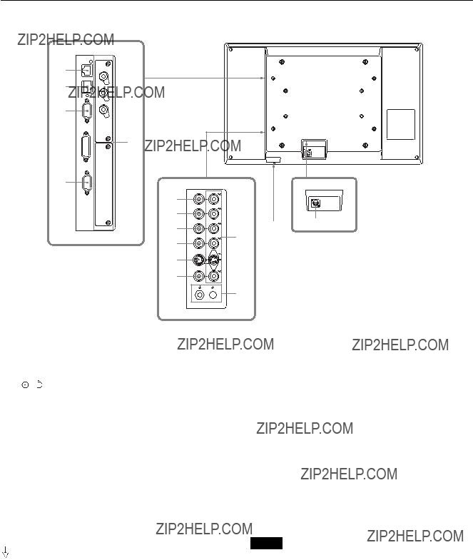
Side/Rear Panel
qs qd
qf
qg qa
qa
qh
5
6
7
8
9
0
21
3
4
a DC 5V/24V IN connector
Connect the DC connector of the supplied AC adaptor.
The power is turned on or off.
The monitor is turned on by pressing side  .
.
c
Outputs the signals input to the input connectors (5 to 0). Connect to the analog input (composite, Y/C, analog component, analog RGB or external sync) of equipment, according to the input signal.
When a cable is connected to one of these connectors, the
d  /I (Equipotential/Function Earth) terminal
 (equipotential) terminal
Connects the equipotential plug.
I (function earth) terminal
Connects the earth cable.
e G/Y IN connector (BNC)
Input connector for G of RGB signals and component Y (luminance) signals.
f B/PB IN connector (BNC)
Input connector for B of RGB signals and PB (blue color difference) of component signals.
g R/PR IN connector (BNC)
Input connector for R of RGB signals and PR (red color difference) of component signals.
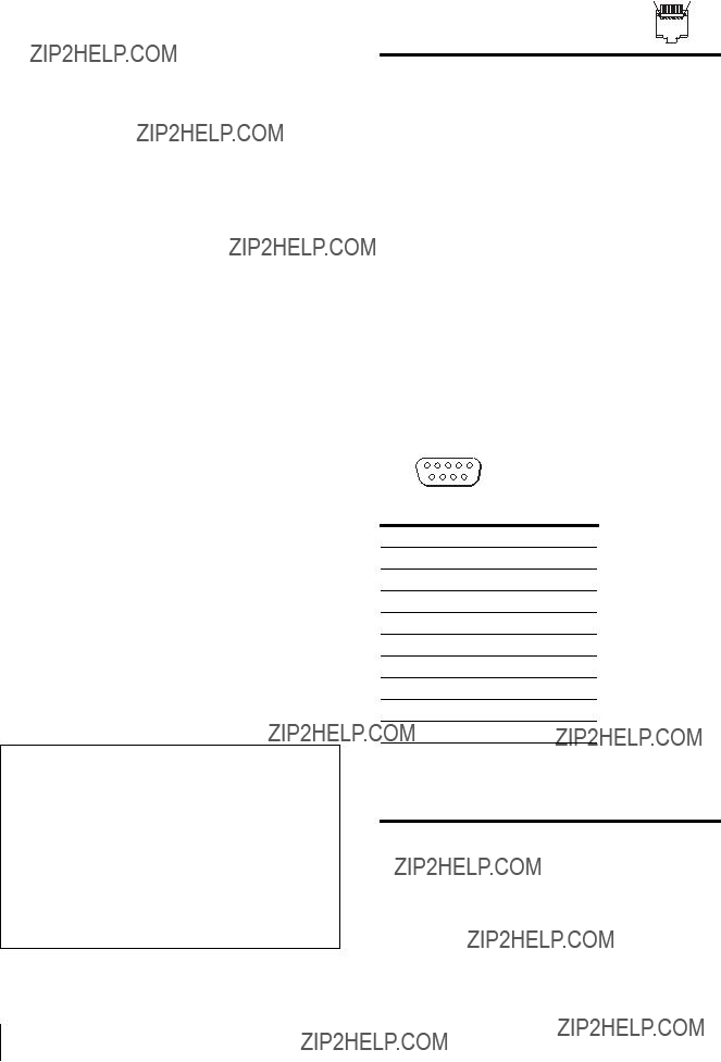
hEXT SYNC IN (external sync input) connector (BNC)
When this unit operates on an external sync signal, connect the reference signal from a sync generator to this connector.
To use the external sync signal, press the function button that EXT SYNC is assigned (F1 button at the factory setting).
Note
When inputting a video signal with the jitters, etc. the picture may be disturbed. We recommend using the TBC (time base corrector).
i Y/C IN connector
Input connector for Y/C signals.
j COMPOSITE IN connector (BNC)
Input connector for composite signals.

k Optional input slot
An optional input adaptor can be installed according to your system configuration (see page 18).
The upper slot is A and the lower slot is B.
Press the
The
lPARALLEL REMOTE connector (modular connector,
Forms a parallel switch and controls the monitor externally.
When the unit is shipped from the factory, a connector cover is attached to this connector. Remove it before using the connector.
For removing the connector cover, see page 18.
For details on the pin assignment and factory setting function assigned to each pin, see page 34.
CAUTION
For safety, do not connect the connector for peripheral device wiring that might have excessive voltage to this port. Follow the instructions for this port.
m SERIAL REMOTE connector
Connect to the network by using a
For removing the connector cover, see page 18.
For details on this connector, refer to the Interface Manual for Programmers (saved in the supplied CD- ROM, Japanese and English only.)
CAUTION
???When an optional LAN cable is connected, use a shield type cable to prevent
???For safety, do not connect the connector for peripheral device wiring that might have excessive voltage to this port. Follow the instructions for this port.
???The connection speed may be affected by the network system. This unit does not guarantee the communication speed or quality of
nSERIAL REMOTE
Connect to the
For details on the pin assignment and factory setting function assigned to each pin, see page 34.
For details, refer to the Interface Manual for Programmers (saved in the supplied
o
Inputs DVI Rev.1.0 applicable digital RGB signal.
To view the signals of the SXGA and higher resolution when the DVI input is selected, use the cable within 3 m (118 1/8 inches) in length.
p HD15 input connector
Inputs an analog RGB video signal (0.7
The Plug & Play function corresponds to DDC2B.
16 Location and Function of Parts and Controls
Connecting the AC
Power Cord
Connect the supplied AC power cord as illustrated. Two kinds of AC plug holders are supplied with this unit. Use the AC plug holder that fits the AC power cord most securely.
1 Plug the AC power cord into the AC IN socket on the AC adaptor. Then, attach the AC plug holder to the AC power cord.
AC IN socket
AC power cord
AC plug holder (Supplied)
2 Slide the AC plug holder over the cord until it locks.
3 Insert the DC IN connector into the DC 5V/24V IN connector on the bottom of this unit until it locks.
To remove the AC power cord
First, pull out the AC plug holder while pressing the lock levers.
Next, pull out the DC IN connector from the DC 5V/24V IN connector while pressing the lock lever.
Connecting the AC Power Cord 17

Installing the Input
Adaptor
Before installing the input adaptor, disconnect the power cord.
1 Remove the panel of the optional input slot.
2 Insert the input adaptor into the slot.
3 Tighten the screws.
Removing the
Connector Cover
When the unit is shipped from the factory, a connector cover is attached to the PARALLEL REMOTE connector and the SERIAL REMOTE connector (RJ- 45).
To use the connector, remove the connector cover as follows.
Before removing the connector cover, disconnect the power cord.
Connector cover
1 Remove the screw of the connector cover.
2 Remove the connector cover.
Save the screw and cover, so that you can reattach the cover if necessary.
Caution
This connector is designed to allow direct contact with conductive circuits. Weak voltage may be present because of a failure in this unit. To prevent patients from touching this connector accidentally, attach the connector cover when the connector is not being used to connect to other devices.
18 Installing the Input Adaptor / Removing the Connector Cover

Selecting the Default
Settings
When you turn on the unit for the first time after purchasing it, select the area where you intend to use this unit from among the options.
The default setting values for each area
+
???
+
???
+
???
MENU
+
???
+
+
3
???
 1
1
ENTER??? 2~3
1 Turn on the unit with the  /
/ (power) switch on the bottom panel.
The SELECT SETTING screen appears.
2 Press the + or ??? button to select the area where you intend to use the unit and press the ENTER button.
If you select either 1, 3 or 5
The confirmation screen is displayed. Confirm the selected area. When the setting is wrong, press the RETURN button to return to the previous screen.
S E L E C T T H I S A R E A ?
N O R T H A M E R I C A
[ E N T E R ] Y E S [ R E T U R N ] NO
If you select either 2 or 4
One of the following screens appears. Press the + or ??? button to narrow the area further and then press the ENTER button.
The confirmation screen is displayed. Confirm the selected area. When the setting is wrong, press the RETURN button to return to the previous screen.

2 If LATIN AMERICA is selected:
4 If ASIA EXCEPT JAPAN is selected:
Customers who will use this unit in the shaded areas shown in the map below should select NTSC AREA.
Other customers should select PAL AREA.
Selecting the Menu
Language
You can select one of seven languages (English, French, German, Spanish, Italian, Japanese, Chinese) for displaying the menu and other
2
+
???
+
???
+
???
+
+
???
 1
1
1 Turn on the unit.
ENTER??? 4~6
3 Press the ENTER button.
The SELECT SETTING screen disappears and the menu item settings suitable for the selected area are applied.
Note
When you have selected the wrong area, set the following items using the menu.
???COLOR TEMP (on page 25)
???COMPONENT LEVEL (on page 27)
???NTSC SETUP (on page 27)
See ???The default setting values for each area??? (page 19) on the setting value.
2 Press the CONTROL button.
The operation buttons are displayed.
3 Press the MENU button.
The menu appears.
The menu presently selected is shown in yellow.
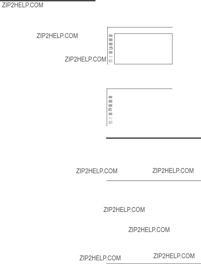
STATUS 1 / 2
4 Press the + or ??? button to select SYSTEM SETTING of the USER CONFIG (User Configuration) menu, then press the ENTER button.
20 Selecting the Menu Language
The setting items (icons) in the selected menu are displayed in yellow.
USER CONFIG ??? SYSTEM SETTING
5 Press the + or ??? button to select ???LANGUAGE,??? then press the ENTER button.
The selected item is displayed in yellow.
USER CONFIG ??? SYSTEM SETTING
6 Press the + or ??? button to select a language, then press the ENTER button.
The menu changes to the selected language.
USER CONFIG ??? SYSTEM SETTING
To clear the menu
Press the MENU button.
The menu disappears automatically if a button is not pressed for one minute.
Using the Menu
The unit is equipped with an
To change the menu language, see ???Selecting the Menu Language??? on page 20.
The current settings are displayed in place of the x marks on the illustrations of the menu screen.
1
+
???
+
???
+
???
RETURN button
1 Press the CONTROL button.
The operation buttons are displayed.
2 Press the MENU button.
The menu appears.
The menu presently selected is shown as a yellow button.
STATUS 1/2
3 Use the + or ??? button to select a menu, then press the ENTER button.
Using the Menu 21

The menu icon presently selected is shown in yellow and setting items are displayed.
USER CONFIG ??? SYSTEM SETTING
4 Select an item.
Use the + or ??? button to select the item, then press the ENTER button.
The item to be changed is displayed in yellow.
If the menu consists of multiple pages, press + or ??? button to go to the desired menu page.
5 Make the setting or adjustment on an item.
When changing the adjustment level:
To increase the number, press the + button. To decrease the number, press the ??? button. Press the ENTER button to confirm the number, then restore the original screen.
When changing the setting:
Press the + or ??? button to change the setting. Press the ENTER button to confirm the setting.
When returning the adjustment or setting to the previous value:
Press the RETURN button before pressing the ENTER button.
Notes
???An item displayed in black cannot be accessed. You can access the item if it is displayed in white.
???If the key inhibit has been turned on, all items are displayed in black. To change any of the items, turn the key inhibit to OFF first.
For details on the key inhibit, see page 31.
To return the display to the previous screen
Press the RETURN button.
To clear the menu
Press the MENU button.
The menu disappears automatically if a button is not pressed for one minute.
About the memory of the settings
The settings are automatically stored in the monitor memory.
22 Using the Menu

Loading USER MEMORY
You can load the picture settings saved in the USER MEMORY menu (on page 31).
+
???
+
???
+
???
+
???
+
???
1 Press the USER MEM button.
The USER MEMORY menu appears.
2 Select the memory number.
+ or ??? button: to select the memory number
3 Press the ENTER button.
After loading the picture settings from the selected memory, the menu disappears.
To stop selecting the memory
Press the USER MEM button.
The USER MEMORY menu disappears.
To reset the settings
Select ???DEFAULT???, then press the ENTER button.
Adjustment Using the
Menus
Items
The screen menu of this monitor consists of the following items.
 STATUS (the items indicate the current settings.)
For the video input
FORMAT
COLOR TEMP
COMPONENT LEVEL
NTSC SETUP
SCAN MODE
POWER SAVING
Model name and serial number
OPTION A and serial number
OPTION B and serial number
For the DVI/HD15 input
FORMAT fH
fV
COLOR TEMP
POWER SAVING
Model name and serial number OPTION A and serial number OPTION B and serial number
 COLOR TEMP/SPACE
COLOR TEMP
MANUAL ADJUSTMENT
COLOR SPACE
 USER CONTROL
For the video input
AUTO CHROMA/PHASE
SUB CONTROL
PICTURE CONTROL
INPUT SETTING
For the DVI/HD15 input
SUB CONTROL
PICTURE CONTROL
 USER CONFIG
SYSTEM SETTING
Loading USER MEMORY / Adjustment Using the Menus 23

KEY INHIBITFor the DVI/HD15 input
 STATUS menu
The STATUS menu is used to display the current status of the unit. The following items are displayed:
???Signal format
???fH
???fV
???Color temperature
???Power saving
???Model name and serial number
???OPTION A and serial number
???OPTION B and serial number
24 Adjustment Using the Menus

 COLOR TEMP/SPACE menu
The COLOR TEMP/SPACE menu is used for adjusting the picture white balance or color space.
You need to use the measurement instrument to adjust the white balance.
Recommended: Konica Minolta color analyzer
???ADJUST GAIN: Adjusts the color balance (GAIN).
???ADJUST BIAS: Adjusts the color balance (BIAS).
???COPY FROM: If you select ???HIGH???, ???LOW??? or ???LOW2???, the white balance data for the selected color temperature will be copied in the ???USER??? setting.
 USER CONTROL menu
The USER CONTROL menu is used for adjusting the picture.
Items that cannot be adjusted depending on the input signal are displayed in black.
For details of input signals and adjustable/setting items, see page 14.
For the video input
???AUTO ADJ VALUE: Selects ON or OFF of the auto adjustment. When you set to OFF, this parameter is reset to the factory setting. When you set to ON, the automatically adjusted value is enabled.
???START: The auto adjustment starts when you display the color bar signals (Full/ SMPTE/EIA) on the screen and press the ENTER button. After adjusting the color intensity, press the MENU button to clear the adjustment screen. After the adjustment is done correctly, the AUTO ADJ VALUE is automatically set to ON.

For the DVI/HD15 input
* The 1/3 menu cannot be adjusted.
USER CONTROL 3/3
???CONTRAST: Adjusts the picture contrast.
???BRIGHTNESS: Adjusts the picture brightness.
???CHROMA: Adjusts color intensity. The higher the setting, the greater the intensity. The lower the setting, the lower the intensity.
???PHASE: Adjusts color tones. The higher the setting, the more greenish the picture. The lower the setting, the more purplish the picture.
???APERTURE: Adjusts the picture sharpness.
The higher the setting, the sharper the picture. The lower the setting, the softer the picture.
???BACKLIGHT: Adjusts the backlight. When the setting is changed, the brightness of the backlight is changed.
26 Adjustment Using the Menus
 USER CONFIG menu
The USER CONFIG menu is used for setting the system, multi display, function button and computer detect.
SYSTEM SETTING
USER CONFIG ??? SYSTEM SETTING
???SMPTE: for 100/0/100/0 signal
???BETA0: for 100/0/75/0 signal
???BETA7.5: for 100/7.5/75/7.5 signal
???ON: The format is always displayed.
???OFF: The display is hidden.
???AUTO: The format is displayed for about 10 seconds when the input of the signal starts.

???ENGLISH: English
???FRAN??AIS: French
???DEUTSCH: German
???ESPA??OL: Spanish
???ITALIANO: Italian
???
 : Japanese
???
 : Chinese
???0: Mode for giving precedence to the picture quality. It takes longer than ???1??? or ???2??? for processing the picture. ???0??? is the factory setting.
???1: The processing time is short and this is a mode suitable for an animation. Even when the picture is constructed by one field such as the proxy picture of XDCAM, a smooth picture is displayed.
???2: The processing time is shorter. As the line flicker is displayed in this mode, it is available for checking the line flicker of the telop work and so on.
MULTI DISPLAY SETTING
28 Adjustment Using the Menus

FUNCTION BUTTON SETTING
Submenu Setting
F1 BUTTON to F4 Assigns the function to the function BUTTONbuttons of the front panel and turns the
function on or off.
You can assign the function from among SCAN, ASPECT, EXT SYNC,
BLUE ONLY, MONO, MULTI DISPLAY, APA and MIRROR IMAGE.
Factory setting
???F1 button: EXT SYNC
???F2 button: SCAN
???F3 button: ASPECT
???F4 button: MULTI DISPLAY
About the function assigned to the function button
SCAN
Press to change the scan size of the picture. Press to switch between NORMAL scan (0% scan), OVER scan (20% over scan) and NATIVE (720P only) (see ???Scan mode image??? on page 29).
ASPECT
Press to set the aspect ratio of the picture, 4:3 or 16:9.
EXT SYNC (external sync)
Press to operate the unit on an external sync signal through the EXT SYNC IN connector.
EXT SYNC works when the component/RGB signals are input.
BLUE ONLY
Press the assigned button to eliminate the red and green signals. Only blue signal is displayed as an apparent monochrome picture on the screen. This facilitates ???chroma??? and ???phase??? adjustments and observation of VCR noise.
MONO
Press the assigned button to display a monochrome picture. When the buttons is pressed again, the monitor switches automatically to color mode.
MULTI DISPLAY
Press the assigned button to display the multi display. Set the multi display setting in the MULTI DISPLAY SETTING menu (see page 28).
APA (Auto Pixel Alignment)
Press to adjust the picture automatically to maximum clarity for the signal input to the HD15 input connector. For finer according to the input signal, see ???DOT PHASE??? on page 27.
When the menu screen is displayed, the APA does not function.
Note
If the APA operation does not finish correctly depending on the input signal, adjust DOT PHASE (page 27).
MIRROR IMAGE
Press the assigned button to flip and display the video signal horizontally. This function is not available for the PRESET 1 signal and the multi display.
Scan mode image
416
COMPUTER DETECT
Note
???PRESET7??? and ???PRESET8??? will only be displayed when ???DVI??? is selected.
 REMOTE menu
30 Adjustment Using the Menus
 KEY INHIBIT menu
You can lock the setting so that they cannot be changed by an unauthorized user.
Select OFF or ON.
If you set to ON, all items are displayed in black, indicating the items are locked.
 USER MEMORY menu
???CONTRAST
???BRIGHTNESS
???CHROMA
???PHASE
COLOR TEMP/SPACE menu
???COLOR TEMP
???ADJUST GAIN
???ADJUST BIAS
???COLOR SPACE
USER CONTROL menu
??? APERTURE
SYSTEM SETTING menu
???GAMMA
???PIC DELAY MIN
Saving the user memory
You can save the 20 picture settings with the name. To load the picture in the saved setting, see ???Loading USER MEMORY??? on page 23.
To save the picture setting
1 Press the + or ??? button to select the memory number in the USER MEMORY menu, then press the ENTER button.
The USER MEMORY setting menu appears.
2 Select ???SAVE???, then press the ENTER button.
The menu for confirming the memory appears.
S AV E TO U S E R M E M O RY 0 1 ?
[ E N T E R ] Y E S
[ R E T U R N ] N O
3 Press the ENTER button.
The current picture settings are saved and the USER MEMORY setting menu appears.
To close the menu without saving the setting
Press the RETURN button.
The USER MEMORY setting menu appears.

To change the name
1 Press the + or ??? button to select the memory number in the USER MEMORY menu, then press the ENTER button.
The USER MEMORY setting menu appears.
2 Press the ??? button to select ???NAME???, then press the ENTER button.
The menu for setting the user name appears.
3 Change the user name.
???Press the ENTER button to move the cursor to the character position to be changed.
???Press the + or ??? button to change the character. Usable characters: ???A to Z???, ???0 to 9???, ???.???, ???/???, ???,???, ???_???,
Usable number of characters: Maximum 18 characters.
???Enter a space to clear the character.
???When the ENTER button is pressed after changing the character, the character is confirmed and the cursor moves to the following character.
4 Press the USER MEM button.
The settings are saved and the USER MEMORY setting menu appears.
To close the menu without saving the setting
Press the RETURN button.
The USER MEMORY setting menu appears.
Troubleshooting
This section may help you isolate the cause of a problem and as a result, eliminate the need to contact technical support.
???The display is colored in green or purple t Select the correct input by pressing RGB or COMPONENT button.
???The unit cannot be operated t The key protection function works. Set the KEY INHIBIT setting to OFF in the KEY INHIBIT menu.
32 Troubleshooting

Specifications
Picture performance
Viewing angle (up/down/left/right, contrast > 10:1)
Input
Composite input (NTSC/PAL) connector BNC type (1)
1
Y: 1
C: 0.286
0.3
RGB/component input connectors BNC type (3)
RGB input: 0.7
Component input: 0.7
External synchronized input connector BNC type (1)
0.3 to 4.0 V
HD15 input connector
R/G/B: 0.7
Sync: TTL level (polarity free, H/V separate sync)
Plug & Play function: corresponds to DDC2B
DVI input connector
TMDS single link Remote input connector
Parallel remote
Modular connector
(ETHERNET) (1)
Optional input slot
2 slots
Signal format:
H: 15 to 45 kHz
V: 48 to 60 Hz
DC IN connector
DC5V/24V (output impedance 0.05 ohms or less)
Output
Composite output connector BNC type (1)
Y/C output connector
RGB/component connectors BNC type (3)
External synchronized output connector
Operating conditions
Temperature
Specifications 33
Storage and transport temperature
0% to 90% (no condensation allowed) Storage and transport pressure
700 hPa to 1060 hPa Accessories supplied
AC adaptor
AC plug holder (2) Instructions for Use (1)
Using the
When you First Use the Monitor (1) Sales Companies Guide (1) Warranty book (1)
Optional accessories
SDI 4:2:2 input adaptor
NTSC/PAL input adaptor
Analog component input adaptor
Monitor stand
Medical Specifications
Protection against electric shock: Class I (No applied parts)
Protection against harmful ingress of water: Ordinary
Degree of safety in the presence of a flammable anesthetic mixture with air or with oxygen or nitrous oxide:
Not suitable for use in the presence of a flammable anesthetic mixture with air or with oxygen or nitrous oxide
Mode of operation: Continuous
Design and specifications are subject to change without notice.
Note
Always verify that the unit is operating properly before use. SONY WILL NOT BE LIABLE FOR
DAMAGES OF ANY KIND INCLUDING, BUT
NOT LIMITED TO, COMPENSATION OR
REIMBURSEMENT ON ACCOUNT OF THE LOSS
OF PRESENT OR PROSPECTIVE PROFITS DUE
TO FAILURE OF THIS UNIT, EITHER DURING
THE WARRANTY PERIOD OR AFTER
EXPIRATION OF THE WARRANTY, OR FOR ANY
OTHER REASON WHATSOEVER.
Pin assignment
1 8
PARALLEL REMOTE connector
Modular connector
You can allocate functions using the REMOTE menu (see page 30).
Wiring required to use the Remote Control
Connect the function you want to use with a Remote Control to the Ground (Pin 5).
SERIAL REMOTE
Available signal formats
The unit is applicable to the following signal formats.
34 Specifications

*1 The frame rate is also compatible with 1/1.001.
*2 Component only
About the preset signal
This unit has a preset memory for signals connected to the DVI and HD15 input terminals (the preset memory). When a preset signal is input, the unit automatically detects the signal type and recalls the data for the signal from the preset memory to adjust it to an optimum picture.
This unit is applicable to the following preset signals.
Specifications 35

PRESET 1
Available HD15 input signal formats
VESA DMT
36 Specifications

Others
Available DVI input signal formats
Range of DVI input signal (available to 1920 ?? 1080 / 60Hz) Vertical frequency: 50.0 to 85.1 Hz Horizontal frequency: 31.5 to 77.0 kHz
Dot clock: 25.175 to 148.000 MHz
Picture size, phase: automatic discrimination by the DE (Data Enable) signal
PRESET 2
PRESET 4
PRESET 6
Specifications 37

PRESET 7 (Selected using DVI in the menu)
PRESET 8 (Selected using DVI in the menu)
38 Specifications

Dimensions
Front
When an optional stand
783 (30 7/8)
479.2 (18 7/8)
392 (15 1/2)
Rear (VESA Mount Instruction)
Side
When an optional stand
124.3 (5)
582.8 (23)
229 (9 1/8)
M6 screw
10 (13/32)
Dimensions 39

Sony Corporation