Camera Adaptor
Operating Instructions
Before operating the unit, please read this manual thoroughly and retain it for future reference.
?? 2004 Sony Corporation
Camera Adaptor
Operating Instructions
Before operating the unit, please read this manual thoroughly and retain it for future reference.
?? 2004 Sony Corporation

WARNING
To prevent fire or shock hazard, do not expose the unit to rain or moisture.
To avoid electrical shock, do not open the cabinet. Refer servicing to qualified personnel only.
For the customers in the USA (for
This equipment has been tested and found to comply with the limits for a Class A digital device, pursuant to Part 15 of the FCC Rules. These limits are designed to provide reasonable protection against harmful interference when the equipment is operated in a commercial environment. This equipment generates, uses, and can radiate radio frequency energy and, if not installed and used in accordance with the instruction manual, may cause harmful interference to radio communications. Operation of this equipment in a residential area is likely to cause harmful interference in which case the user will be required to correct the interference at his own expense.
You are cautioned that any changes or modifications not expressly approved in this manual could void your authority to operate this equipment.
The shielded interface cable recommended in this manual must be used with this equipment in order to comply with the limits for a digital device pursuant to Subpart B of Part 15 of FCC Rules.
For the customers in Europe (for
This product with the CE marking complies with both the EMC Directive (89/336/EEC) and the Low Voltage Directive (73/23/EEC) issued by the Commission of the European Community.
Compliance with these directives implies conformity to the following European standards:
???EN60950: Product Safety
???
???
This product is intended for use in the following Electromagnetic Environment (s):
E1 (residential), E2 (commercial and light industrial),
E3 (urban outdoors) and E4 (controlled EMC environment, ex. TV studio).
2

3

Overview
The
Component signal transfer method
This unit enables transfer of Y,
The maximum triaxial cable length that can be used to connect this unit to a camera control unit is max. 750 m (when using a Belden ??8.5 mm cable) or 1125 m (when using a Belden ??13.2 mm cable).
Electrical shock prevention function
To prevent electrical shock, this unit shuts off any high- voltage power supply whenever there is an incomplete connection.
Coaxial cable connection
When necessary, this unit can be connected to a camera control unit via a coaxial cable.*
*This unit???s triaxial connector must be refitted to enable connection of a coaxial cable. Consult your Sony dealer for details.
Variety of input/output connectors
Input/output connectors for the following signals are provided:
???Video signal output/input* for teleprompter
???Return video signal output
???Intercom/program output for connected headset
???Microphone or
*It is required to perform the internal adjustment to change the teleprompter video signal transfer direction to input. Contact your Sony dealer for more information on changing the teleprompter video signal transfer direction.
4 Overview
Location and Function of Parts
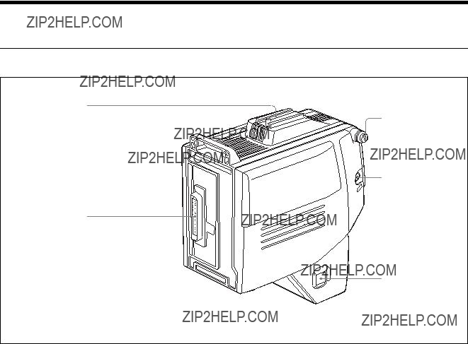
Front and Right Side
Accessory Shoe
Shoulder Strap fitting
c CALL button
a Camera connector (PRO
b POWER switch
a Camera connector (PRO
Connects to the camera???s
b POWER switch
Turns this unit???s power supply on and off.
To power the unit, set the switch to EXT or CCU according to the type of power source being used.
control panel. This unit???s back tally indicator also lights if the TALLY switch is in the ON position.
Set this to the a (OFF) position to turn off the power supply.
When this unit is connected to a camera control unit via a triaxial cable, the intercom communication function continues to operate even after the power is turned off.
c CALL button
Press this button to call the operator of the camera control unit or remote control panel. Pressing this button lights the tally indicator (red) or the CALL button (red) on the camera control unit, and on the remote

Switches and Knobs on the Rear
aRET 1/RET 2/RET 3/ PROMPTER buttons
b TALLY switch
c Back tally indicator
d CURSOR switch
e Cursor knobs
f PROD/ENG switch
g PROGRAM knob
h INTERCOM knob
i MIC/LEVEL switch
a RET 1/RET 2/RET 3/PROMPTER buttons
Select the return video signal* to be output from the RETURN connector and to the camera???s viewfinder. Press the RET 1, RET 2 or RET 3/PROMPTER button to select the return video signal 1, return video signal 2, or return video signal 3 or the prompter signal from the camera control unit.
To show the shooting picture on the viewfinder screen, release the button. The return video signal which selected last is still output from the RETURN connector if the button is released.
*Return video: Video signals that are sent from a camera to a camera control unit and returned to the same or another camera so that the camera operators can check the recorded image.
b TALLY switch
Set this switch to the ON position to activate the back tally indicator c.
c Back tally indicator
When the TALLY switch b is in the ON position, this indicator lights in response to this unit???s operating status. During recording, this indicator lights in red. It also lights when the CALL button on the camera control unit or remote control panel has been pressed.
d CURSOR switch
Selects whether or not to display a box cursor in the
B: Displays box cursor B.
A: Displays box cursor A.
OFF: No box cursor is displayed.
e Cursor knobs
When the CURSOR switch d is set to A or B, these adjust the position and size of the box cursor that is displayed in the viewfinder of the
WIDTH: Adjusts the width of the box cursor.
HEIGHT: Adjusts the height of the box cursor.
f PROD/ENG (producer/engineer select) switch
Selects the channel for transferring intercom audio. PROD: Uses the producer line.
ENG: Uses the engineer line.
Note
When the INCOM selector on the
6 Location and Function of Parts

camera control unit regardless of the PROD/ENG switch position.
g PROGRAM knob
Adjusts the program audio reception level.
When using a
h INTERCOM knob
Adjusts the intercom audio reception level.
Setting the MIC/LEVEL switch ito OFF/FRONT will enable the audio level knob on the
Note
If you switch the position of the MIC/LEVEL switch i, settings of the program audio reception level and intercom audio reception level are changed. Adjust them again using the PROGRAM knob g and INTERCOM knob h.
i MIC/LEVEL switch
Decides the on/off of the intercom microphone and the adjusting method of the reception level.
ON/REAR: Sets the intercom microphone to on. The reception level is adjusted using the INTERCOM knob.
OFF/REAR: Sets the intercom microphone to off. The reception level is adjusted using the INTERCOM knob.
OFF/FRONT: Sets the intercom microphone to off. The reception level is adjusted using the camera???s front panel.
At this position, while you are pressing the VTR start/ stop button on the camera, the microphone of the intercom is on.

Connectors and Switches on the Rear and Left Side
b UHF portable tuner taps
a CCU connector
c INTERCOM/PROGRAM connector
h DC OUT connector
d EARPHONE jack
f AUDIO IN +48V CH1/CH2 switches
j PROMPTER connector
aCCU (Camera control unit) connector (CA- TX50: Kings triaxial connector,
Fischer triaxial connector)
Connect a
b UHF portable tuner taps
When using an optional
For details of attaching and using the
*
Using a coaxial cable to connect the camera control unit
The CCU connector must be refitted to enable connection of a coaxial cable. Note that connecting a coaxial cable makes it impossible for this unit to receive power from the camera control unit. Use a
Contact your Sony dealer for more information on refitting the CCU connector.
c INTERCOM/PROGRAM connector (XLR
Connect a headset for monitoring intercom audio or program audio. Normally, a monaural
An internal adjustment can be made to enable both sides of the headset to receive audio, with intercom audio on the left side and program audio on the right side.
Contact your Sony dealer for further information on this internal adjustment.
8 Location and Function of Parts

d EARPHONE jack (mini jack)
Connect an earphone for monitoring intercom audio.
eAUDIO IN CH1/CH2 (audio input select) switches
Select the source for signals to be transferred via the camera control unit???s channel 1 and channel 2.
FRONT/MIC: Transfers audio from a microphone on the camera to the camera control unit.
REAR/MIC: Transfers audio from a microphone connected to this unit???s AUDIO IN (CH1/CH2) connector to the camera control unit. REAR/LINE: Transfers audio from a line output connected to this unit???s AUDIO IN (CH1/CH2) connector to the camera control unit.
fAUDIO IN +48V CH1/CH2 (power supply select) switches
Selects whether or not to supply power to a microphone connected via the AUDIO IN CH1 and CH2 connectors.
+48V: Supplys
OFF: Do not supply power to microphone. Leave this switch in the ON position when using a microphone of phantom powering* type.
Note
Except when a microphone of phantom powering type is used, be sure to set this switch to OFF.
Failing to do so results in that the noise may occur or that the devices connected to the unit may be damaged.
*Phantom powering: Powering method for operating condenser microphones by supplying power via a bias power source and an amplifier. Because no DC voltage is present in the audio channel, it is called ???phantom powering???.
gAUDIO IN (CH1/CH2) (audio inputs, channel 1 and channel 2) connectors (XLR
Connect external microphones or other equipment as sources for audio to be transferred to the camera control unit???s channel 1 or 2.
Set the AUDIO IN CH1/CH2 switch to select the channel for the connected equipment.
h DC OUT connector
Use this connector when supplying power (DC 10.5 to 17V, Max. 1.5 A) to a
Note
Never connect a unit that has a power consumption rating of more than 18 W.
i DC IN connector (XLR
When connecting this unit to a camera control unit via a coaxial cable, use this connector for a
Adaptor (supplied separately). Connect the DC power cord of the
jPROMPTER (teleprompter video signal input/ output) connector (BNC type)
Outputs teleprompter video signals* from the camera control unit. (This unit can treat color teleprompter video signals.)
If you have made the internal adjustment to change the teleprompter video signal transfer direction so that signals are transferred from this unit to the camera control unit, this connector becomes the input connector for teleprompter video signals.
Contact your Sony dealer for further information on the internal adjustment to change the teleprompter video signal transfer direction.
*Teleprompter video signals: Video signals for prompter which displays scripts in the television monitor by the camera lens or on the face of a
kRETURN (return video signal output) connector (BNC type)
Outputs return video signals from a camera control unit. Use the RET 1, RET 2 and RET 3/PROMPTER buttons to switch among the three return video signals.

Mounting on Video Camera
This unit is dockable with the
Note
Turn the POWER switch off before mounting the unit on the camera.
1 Fit the projection on the bottom of this unit into the slot on the camera.
Camera
Projection
Slot
Groove
2 Slide the unit along the groove on the camera, and press firmly until fixed.
3 Tighten the two screws (M4 ??? 12) in the figure.
10 Mounting on Video Camera
4 Tighten the two screws (M4 ??? 6) to fix the shoulder pad.
M4 ??? 6 screws
Note
Slide the shoulder pad to its central position before tightening the screws.
Otherwise the screws may not be properly fixed.
Removing from the camera
Follow the procedure above in reverse.
Notes on Use
Use and storage locations
Avoid using or storing the unit in the following places:
???Where it is subject to extremes of temperature (operating temperature:
Note that in summer the temperature in a car with the windows closed can reach 50??C (122??F).
???Very damp or dusty places.
???Where rain is likely to reach the unit.
???Places subject to severe vibration.
???Near strong magnetic fields
Near transmitting stations generating strong radio waves.
Avoid violent impacts
Dropping the unit, or otherwise imparting a violent shock to it, is likely to cause it to malfunction.
Do not cover with cloth
While the unit is in operation, do not cover it with a cloth or other material. This can cause the temperature to rise, leading to a malfunction.
After use
Turn the POWER switches on the unit and camera control unit off.
Care
If the body of the unit is dirty, wipe it with a dry cloth. For severe dirt, use a soft cloth steeped in a small amount of neutral detergent, then wipe dry. Do not use volatile solvents such as alcohol or thinners, as these may damage the finish.
Notes on Use 11

Specifications
General
Power requirements
When supplied via the CCU connector: 180 V DC
When supplied via the DC IN connector: 12 V DC (10.5 to 17 V DC)
Power consumption
When 180 V DC is supplied via the CCU connector: max. 0.37 A
When 12 V DC is supplied via the DC IN connector: max. 4.8 A
Operating temperature
20% to 90% Storage temperature
206 ??? 212 ??? 131 mm
(8 1/8 ??? 8 3/8 ??? 5 1/4 inches) (w/h/d)
Input/output connectors
Accessories supplied
Operating Instructions (1)
Warranty booklet (1)
Accessories not supplied
Triaxial cable (Belden)
*
Design and specifications are subject to change without notice.
12 Specifications

Sony Corporation