1 YEAR
LIMITED WARRANTY
For one (1) year from purchase date for the original purchaser's residential, non-commercial use, SNAPPER - A Division of SIMPLICITY Manufacturing, Inc., through any authorized TURF CRUISER dealer, will replace, free of charge (except for taxes where applicable), any part or parts found upon examination by the factory at McDonough, Georgia, to be defective in material or workmanship or both.
For ninety (90) days from purchase date for the original purchaser's commercial, rental, or other non-residential use,
SNAPPER - A Division of SIMPLICITY Manufacturing, Inc., through any authorized TURF CRUISER dealer will replace, free of charge (except for taxes where applicable), any part or parts found upon examination by the factory at McDonough, Georgia, to be defective in material or workmanship or both
All transportation costs incurred by the purchaser in submitting material to an authorized TURF CRUISER dealer for replacement under this warranty must be paid by the purchaser.
This warranty does not apply to engines and their components, and batteries, as these items are warranted separately. This warranty does not apply to parts that have been damaged by accident, alteration, abuse, improper lubrication, normal wear, or other cause beyond the control of SNAPPER - A Division of SIMPLICITY Manufacturing, Inc. This warranty does not cover any machine or component that has been altered or modified, changing safety, performance, or durability.
Batteries have a one (1) year warranty period with free replacement if required for one (1) year from the original purchase date. SNAPPER - A Division of SIMPLICITY Manufacturing, Inc., will not be responsible for any installation cost incurred. The battery warranty only covers original equipment batteries and does not cover damage to the battery or machine caused by neglect or abuse, destruction by fire, explosion, freezing, overcharging, or improper maintenance.
There is no other express warranty.
DISCLAIMER OF WARRANTY
Implied warranties, including those of merchantability and fitness for a particular purpose, are limited to one
(1) year from purchase date for the original purchaser's residential or other non-commercial use, and ninety (90) days from the purchase date for the original purchaser???s commercial, rental or other non-residential use, and up to the extent permitted by law and all implied warranties are excluded. This is the exclusive remedy. Liabilities for consequential damages, under any and all warranties are excluded.
Some states do not allow limitations on how long an implied warranty lasts, or do not allow the exclusion or limitation of incidental or consequential damages, so the above limitation or exclusion may not apply to you.
This warranty gives you specific legal rights, and you may also have other rights which vary from state to state.
WARNING: THE USE OF REPLACEMENT PARTS OTHER THAN GENUINE SNAPPER PARTS MAY IMPAIR
THE SAFETY OF SNAPPER PRODUCTS AND WILL VOID ANY LIABILITY AND WARRANTY BY SNAPPER
ASSOCIATED WITH THE USE OF SUCH PARTS.
IMPORTANT: Please fill out the attached Product Registration Card immediately and mail to:
Snapper???s Product Registration Center, P.O. Box 1379, McDonough, Georgia. 30253


 12V ACCESSORY


 SLOW
SLOW


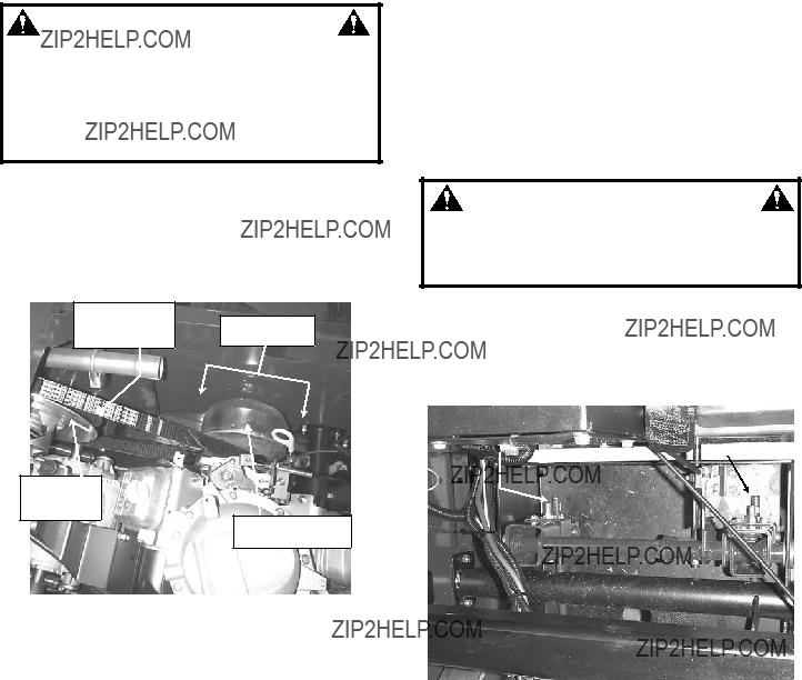


 30 AMP FUSE

 WARNING
 WARNING