Siemens BACnet ATEC
Owner's Manual
Siemens Industry, Inc.
Siemens BACnet ATEC
Owner's Manual
Siemens Industry, Inc.
Technical specifications and availability subject to change without notice.
?? 2010 Copyright Siemens Industry, Inc.
We reserve all rights in this document and in the subject thereof. By acceptance of the document the recipient acknowledges these rights and undertakes not to publish the document nor the subject thereof in full or in part, nor to make them available to any third party without our prior express written authorization, nor to use it for any purpose other than for which it was delivered to him.

Copyright Notice
Copyright Notice
Notice
Document information is subject to change without notice by Siemens Industry, Inc. Companies, names, and various data used in examples are fictitious unless otherwise noted. No part of this document may be reproduced or transmitted in any form or by any means, electronic or mechanical, for any purpose, without the express written permission of Siemens Industry, Inc.
Warning
This equipment generates, uses, and can radiate radio frequency energy. If equipment is not installed and used in accordance with the instructions manual, it may cause interference to radio communications. Equipment has been tested and found to comply within the limits for a Class B digital device pursuant to Part 15 of the FCC rules. These limits are designed to provide reasonable protection against such interference when operated in a commercial environment. Operation of this equipment in a residential area is likely to cause interference. Residential area equipment users are required to take whatever measures necessary to correct the interference at their own expense.
Service Statement
Control devices are combined to make a system. Each control device is mechanical in nature and all mechanical components must be regularly serviced to optimize their operation. Siemens Industry, Inc. branch offices and authorized distributors offer Technical Support Programs that will ensure continuous,
For further information, contact your nearest Siemens Industry, Inc. representative. Copyright 2010 by Siemens Industry, Inc.

Copyright Notice
radio communications. However, there is no guarantee that interference will not occur in a particular installation. If this equipment does cause harmful interference to radio or television reception, which can be determined by turning the equipment off and on, the user is encouraged to try to correct the interference by one or more of the following measures:
???Reorient or relocate the receiving antenna.
???Increase the separation between the equipment and receiver.
???Connect the equipment into an outlet on a circuit different from that to which the receiver is connected.
???Consult the dealer or an experienced radio/TV technician for help.
To the Reader
Your feedback is important to us. If you have comments about this manual, please submit them to: mailto:Sbt_technical.editor.us.sbt@siemens.com
Credits
APOGEE, APOGEE GO, InfoCenter Administrator, InfoCenter Report Manager, InfoCenter Server, InfoCenter Suite, Insight, Staefa, and TALON are registered trademarks of Siemens Industry, Inc.
Other product or company names mentioned herein may be the trademarks of their respective owners.
Printed in USA
4


6

How To Use This Manual
How To Use This Manual
This manual is written for the owner and user of the Siemens Industry BACnet VAV Actuator. It is designed to help you become familiar with the Siemens BACnet VAV Actuator and its applications.
This section covers manual organization, manual conventions, symbols used in the manual, and other information that will help you use this manual.
Manual Organization
This manual contains the following chapters:
???Chapter 1, Hardware, describes the hardware components and the accessories that are used with the BACnet VAV Actuator.
???Chapter 2, Applications for BACnet VAV Actuator, describes the control applications available in the model of the BACnet VAV Actuator that includes a terminal block for wireable input/output connections.
???Chapter 3, Point Database, defines the point database descriptors and includes address and applications.
???Chapter 4, Troubleshooting, describes basic corrective measures you can take should you encounter a problem when using the BACnet VAV Actuator. For issues not covered in this chapter, consult your local Siemens Industry representative.
???The Glossary describes the terms and acronyms used in this manual.
???The Index helps you locate information presented in this manual.
Manual Conventions
The following table lists conventions to help you use this manual in a quick and efficient manner.

How To Use This Manual
Cross references to other information are indicated with an arrow and the page number, enclosed in brackets: [???92]
For more information on creating flowcharts, see Flowcharts [???92].
Manual Symbols
The following table lists the safety symbols used in this manual to draw attention to important information.

Chapter 1 ??? Product Overview
Chapter 1 ??? Product Overview
The BACnet Actuating Terminal Equipment Controller (ATEC) is the Siemens Industry FLN controller used in pressure independent Variable Air Volume applications (See the following figure.). It provides Direct Digital Control (DDC) for eight applications, and can operate independently as a
Table 1 lists the BACnet ATEC products that are covered:
Ordering Notes

Chapter 1 ??? Product Overview
Siemens BACnet ATEC
Hardware Inputs
Analog
???Air Velocity Sensor (AVS)
???Duct temperature sensor (optional) ??? Application 2861
???Room temperature sensor (RTS)
???Room temperature setpoint dial (optional)
Digital
???Night mode override (optional)
???Wall switch (optional)
Hardware Outputs
Analog
???None
10
Power Wiring
The controller is powered by 24 Vac. Power wiring connects to the two screw terminals on the controller labeled ???C??? (Common) and ???H??? (Hot) on the terminal block labeled ???24 VAC???. No earth ground connection is required. See the following figure.

Chapter 1 ??? Product Overview
Communication Wiring
The controller connects to the field panel by means of a Floor Level Network (FLN) trunk. Communication wiring connects to the three screw terminals on the controller labeled ???+??? (positive),
Controller LED Indicators
The controller has six Light Emitting Diode (LED) indicators (see the figure Siemens
BACnet ATEC).

Chapter 1 ??? Product Overview
Temperature Sensors
Room Temperature Sensor
The controller room temperature sensor connects to the controller by means of a cable terminated at both ends with a
Duct Temperature Sensor
An optional duct temperature sensor provides duct air temperature sensing inputs to the controller.
For more information about temperature sensors, contact your local Siemens Industry representative.
Related Equipment
???Autozero Module (optional)
???Relay Module
???Damper Actuator(s)
???Duct Temperature Sensor (optional)
???Room Temperature Sensor
Contact your local Siemens Industry representative for product numbers and more information.

Chapter 2 ??? Applications
Chapter 2 ??? Applications
Basic Operation
The BACnet ATEC provides Direct Digital Control (DDC) for Variable Air Volume (VAV) terminal box applications. Temperature control varies with the application. If present, heating can be provided by hot water, up to three stages of electric reheat, or optional baseboard radiation.
Sequencing Logic (optional)
This application has the additional capability to sequence the flow and mechanical heating when heated supply air is available.
Control Temperature Setpoints
The controller maintains a specified temperature setpoint based on Day/Night mode, or the heating/cooling mode, or the setpoint dial (if used).
Day/Night Mode
The controller maintains the specified day setpoint temperature during daytime hours and the specified night setpoint at night.
Night Mode Override Switch
If the ROOM TEMPERATURE SENSOR has an override switch, it can be used to command the controller into day mode for an adjustable period of time. This only affects a controller in night mode.
Control Loops

Chapter 2 ??? Applications
Calibration
Air Velocity Sensor
Calibration of the controller's internal air velocity sensor is periodically required to maintain accurate air velocity readings. Calibration may be set to take place automatically or manually.
Autozero Module (AZM)
Used when damper cannot be closed and constant airflow is needed.
???For a controller used with an AZM, calibration occurs without closing the damper. Application 6520, 6521, 6522, 6523.
???For a controller used without an AZM, the damper is briefly commanded closed to get a zero airflow reading and an accurate damper position during calibration. Application 6520, 6521, 6522, 6523.
Hot Water Valve
Calibration of a hot water valve (if used) is done by briefly commanding the valve closed. Application 2863, 2865, 2867.
Damper Status Operation
It is possible, after a period of operation, for the calculated damper position to differ from the actual (physical) damper position.
If this occurs, the controller will automatically compensate for any difference by readjusting the calculated damper position. This calculated position may not match the actual position.
If the air velocity sensor fails, the controller uses pressure dependent control. The temperature loop controls the operation of the damper.
If the room temperature sensor fails, then the controller operates using the last known temperature value.
Heating and Cooling Switchover
The heating/cooling switchover determines whether the controller is in heating or cooling mode by monitoring the room temperature and the demand for heating and cooling (as determined by the temperature control loops).

Chapter 2 ??? Applications
Modulate Damper During Heating Mode (optional)
CAUTION
If the damper is set to modulate in heating mode, make sure the controller is in the appropriate mode for the current supply air temperature.
Applications that have a heating source (valve/electric) can be configured to modulate the flow setpoint in sequence with the heating source.
Hot Water Reheat
CAUTION
Do not set HTG FLOW MIN to 0 cfm (0 lps). A minimum airflow should be provided across the heating coils when the heating valve is open.
When the controller is in cooling mode, the heating valve(s) are closed.
The heating loop modulates the heating valve(s) to warm up the room. In cooling mode, the heating valve is closed.
Electric Reheat
CAUTION
Verify that the equipment is supplied with safeties by others to ensure that there is airflow across the heating coils when they are to be energized.
The heating loop controls up to three stages of electric reheat to warm up the room. The electric reheat is time modulated using a duty cycle. When the controller is in cooling mode, the electric heat is OFF at all times.
Notes
1.If the temperature swings in the room are excessive or if there is trouble in maintaining the setpoint, contact your local Siemens Industry representative for more information.
2.The BACnet ATEC, as shipped from the factory, keeps all associated equipment OFF. The controller and its equipment are released to application control at
16
Chapter 2 ??? Applications
3.???Safeties by Others???: This note implies that the associated equipment has safety features installed, for example adding mechanical stops to the dampers.
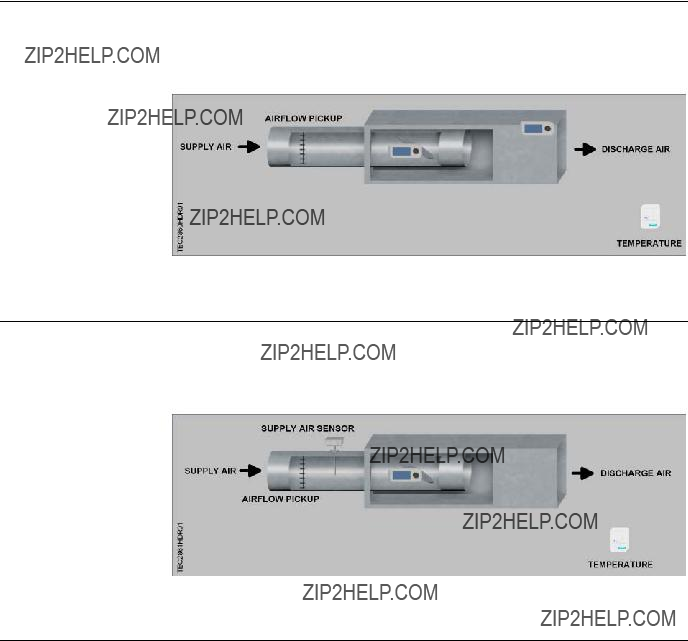
Application 2860 VAV Cooling Only
In Application 2860, the controller modulates the supply air damper of the terminal box for cooling. In order for it to work properly, the central
See the following figure.
Application 2861 VAV Cooling or Heating
In Application 2861, the controller modulates the supply air damper of the terminal box for cooling and heating. In order for it to work properly, the central
See the following figure.
Application 2862 VAV with Electric Reheat or Baseboard Radiation

Chapter 2 ??? Applications
Baseboard Radiation
Baseboard radiation can be a
If the controller is in cooling mode, the heating valve is closed. When in heating mode, the controller will operate the heating valve to maintain the heating setpoint.
Electric Heat Interlock
CAUTION
Do not set EHEAT FLOW (the defined minimum) to less than 5%; otherwise, the electric heat interlock will be disabled.
The electric heat stages will be disabled (turned off) when the electric heat airflow is less than the defined minimum.
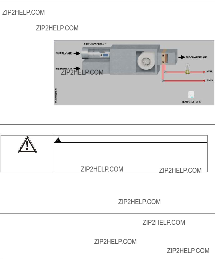
Application 2863 VAV with Hot Water Reheat
In Application 2863, the controller modulates the supply air damper of the terminal box for cooling and controls a hot water valve or baseboard radiation for heating. When in heating, the terminal box either maintains minimum airflow or modulates the supply air damper. In order for the terminal box to work properly, the central
See the following figures.
18

Chapter 2 ??? Applications
Application 2864 VAV Series Fan Powered with Electric Reheat
In Application 2864, the controller modulates the supply air damper of the terminal box for cooling and controls stages of electric reheat for heating. When in heating, the terminal box either maintains minimum airflow or modulates the supply air damper. Application 2864 has a series fan for air circulation. In order for the terminal box to work properly, the central
See the following figure.
Fan Operation
Chapter 2 ??? Applications
[insert TEC2564CD]
Application 2865 VAV Series Fan Powered with Hot Water Reheat
In Application 2865, the controller modulates the supply air damper of the terminal box for cooling and modulates a hot water valve for heating. When in heating, the terminal box either maintains minimum airflow or modulates the supply air damper. Application 2865 has a series fan for air circulation. In order for the terminal box to work properly, the central
See the following figure.
Fan Operation
CAUTION
On series fan powered terminal boxes, the terminal box fan must be controlled/interlocked to start either before or at the same time as the central air handler. Failure to do so may cause the terminal box fan to rotate backwards and cause consequent damage at start up.
In day mode, the fan is ON all the time. In night mode, the fan cycles on when heating or cooling is required.
Application 2866 VAV Parallel Fan Powered with Electric Reheat
In Application 2866, the controller modulates the supply air damper of the terminal box for cooling and controls stages of electric reheat for heating. When in heating, the terminal box either maintains minimum airflow or modulates the supply air damper. Application 2866 has a parallel fan that
20
Chapter 2 ??? Applications
See the following figure.
Fan Operation
The fan turns on when heating is required.
[insert TEC2566CD]
Application 2867 VAV Parallel Fan Powered with Hot Water Reheat
In Application 2867, the controller modulates the supply air damper of the terminal box for cooling and modulates a hot water valve for heating. When in heating, the terminal box either maintains minimum airflow or modulates the supply air damper. Application 2867 has a parallel fan that
See the following figure.

Chapter 2 ??? Applications
Fan Operation
The fan turns on when heating is required.
[insert TEC2567CD]
Application 2897 Slave Mode
Application 2897 is the slave mode application for the BACnet ATEC (see Ordering Notes [??? 9] for product numbers). Slave mode is the default application that comes up when power is first applied to the controller. Slave mode provides no control. Its purpose is to allow the operator to perform equipment checkout before a control application is put into effect and to set some basic controller parameters (CTLR ADDRESS, APPLICATION, etc.). A controller in default state can also be used as a point extension device by unbundling spare I/O points at the field panel.
Using Auxiliary Points
It is possible to have extra points available on a BACnet VAV Controller ??? Electronic Output in addition to the ones used by the current application that is running in the controller. If these extra points are to be controlled by a field panel, then they must be unbundled at the field panel.
Using the Controller as a Point Extension Device
If the controller is only used as a point extension device, with no control application in affect, its application must be set to slave mode and points must be unbundled at the field panel. All points must be controlled from the field panel in order to be used.
22

Chapter 2 ??? Applications
DO 3, DO 4, and DO 5 may be used as separate DOs or in pairs to control a motor as shown in the example.
NOTE:
If using either a motor or DOs as auxiliary points, be sure to set MTR SETUP to the correct value. If using a pair of DOs to control a motor, then the DOs cannot be unbundled. Only MTR COMD can be unbundled to control the motors.
Contact your local Siemens Industry representative for other combinations of DOs and motors.

Chapter 3 ??? Point Database
Chapter 3 ??? Point Database
Chapter 3 presents a description of the BACnet VAV Controller ??? Electronic Output point database, including point descriptors, point addresses, and a listing of applications in which each point is found.
Chapter 3 ??? Point Database
Chapter 3 ??? Point Database

1)
2)
Points not listed are not used in this application.
Point numbers that appear in brackets { } may be unbundled at the field panel.
29

Chaper 4 ??? Troubleshooting
Chaper 4 ??? Troubleshooting
This chapter describes corrective measures you can take should you encounter a problem when using a BACnet ATEC.
You are not required to do any controller troubleshooting. You may want to contact your local Siemens Industry representative if a problem occurs or you have any questions about the controller.
NOTE:
When troubleshooting, record what the problem is and what actions were performed immediately before the problem occurred. Being able to describe the problem in detail is important, should you need assistance from your local Siemens Industry representative.
Basic Service Information
Always remove power to the BACnet ATEC when installing or replacing it. Since the controller does not have a power switch, the recommended method of removing power to a locally powered controller is to turn OFF the power to the 24 Vac transformer. The recommended method of removing power to a controller on a power cable (even to service a single controller) is to turn OFF the power at the transformer.
NOTE:
When removing power to a controller to perform maintenance or service, make sure that the person in charge of the facility is aware of this and that appropriate steps are taken to keep the building in control.
Never remove the cover from the BACnet ATEC. There are no serviceable parts inside. If a problem is found with this device, contact your local Siemens Building Technologies representative for replacement. An
Preventive Maintenance
Most controller components are designed so that, under normal circumstances, they do not require preventive maintenance. Periodic inspections, voltage checks, and point checks are normally not required. The rugged design makes most preventive maintenance unnecessary. However, devices that are exposed to dusty or dirty environments may require periodic cleaning to function properly.
30
Chaper 4 ??? Troubleshooting
Safety Features
The controller board stores the controller's address, applications, and point values. In the event of a power failure or a reset, these values are retrieved from the controller's permanent memory and are used by the controller unless overridden by a field panel. If one of the following conditions occurs, the controller will activate safety features present in its
???Sensor failure.
???Loss of power. Upon controller power loss, communication with the controller is also lost. The controller will appear as failed (*F*) at the field panel.
Controller LEDs
NOTE:
The TX and RX LEDs indicate communication over the FLN.
To determine if the controller is powered up and working, verify that the Basic Sanity Test (BST) Light Emitting Diode (LED) is flashing ON/OFF once per second. The controller contains seven LEDs located on the circuit board. See the Controller LED lndicators [??? 12] section of Chapter 1 - Product Overview [??? 9] for more information about LEDs.

Glossary
Glossary
The glossary contains terms and acronyms that are used in this manual. For definitions of point database descriptors, see Chapter 3 - Point Database [??? 24] , in this manual.
Glossary
field panel
A device containing a microprocessor for centralized control of system components and equipment controllers.
FLN
Field Level Network. Network consisting of equipment controllers, FLN end devices, fume hoods, etc.
lps
Liters per Second.
loopout
Output of the control loop expressed as a percentage.
HMI
Human Machine Interface. Terminal and its interface program that allows you to communicate with a field panel or equipment controller.
override switch
Button on a room temperature sensor that an occupant can press to change the status of a room from unoccupied to occupied (or from night to day) for a predetermined time.
pressure independent
Variable Air Volume (VAV) room temperature control system in which the temperature drives an airflow setpoint.
PID
Proportional, Integral, Derivative.
RTS
Room Temperature Sensor.
setpoint
Virtual point that stores a point value such as a temperature setting. Points that monitor inputs, such as temperature, report actual values.
SI units
Systeme International d'Unites. The international metric system.

Glossary
slave mode
Default application that displays when power is first applied to an equipment controller. No control action is initiated in the slave mode.
Type of control offered by a controller that is providing independent DDC control to a space.
Terminal Equipment Controller
Siemens Industry, Inc. product family of equipment controllers (one is the BACnet VAV Controller - Electronic Output) that house the applications software used to control terminal units, such as heat pumps, VAV terminal boxes, fan coil units, unit ventilators, etc.
UI
Universal Input. Can be used as an AI or DI. An AI input is a point receiving a signal that represents a condition that has more than two states. A DI input is a physical input point that receives a
unbundle
Term used to describe the entering of a point that resides in a controller's database into the field panel's database so that it can be monitored and controlled from the field panel.
VAV
Variable air volume. Ventilation system that changes the amount of air supplied to and exhausted from the rooms served.
34

Index
Index
A
Air Velocity Sensor (AVS), 12 algorithm, 33
application 2562 baseboard radiation, 11
application 2564 control drawing, 21
Application 2564
fan operation, 21
application 2566 control drawing, 23 fan operation, 23
application 2567 control drawing, 24
Application 2567
fan operation, 24
Application 2597
using auxiliary points, 24 application 2860
control drawing, 19 overview, 19
application 2861 control drawing, 19 overview, 19
application 2862 baseboard radiation, 20 control drawing, 19 electric heat, 20
electric heat interlock, 20 overview, 19
application 2863
control drawing, 20 overview, 20
application 2864 overview, 21 application 2865 overview, 22
Application 2865 fan operation, 22
application 2866 overview, 23 application 2867 overview, 23
Application 2897
overview, 24
using controller as point extension device, 24 applications
calibration, 17, 27 control loops, 16
control temperature setpoints, 16 damper status operation, 17 day/night mode, 16
electric reheat:stage 1, 11, 18, 21, 23 electric reheat:stage 2, 11, 18, 21, 23 electric reheat:stage 3, 18
heating and cooling switchover, 17 hot water reheat, 11, 18, 20, 22, 23
modulate damper during heating mode, 18 night mode override switch, 16
notes, 11, 18 sequencing logic, 16
35

Index
B
Basic Sanity Test (BST), 32 basic service information, 31 BST LED, 32
C
centralized control, 33 communication wiring, 14 control loop, 33 controller
LEDs/LED indicators, 32
D
DDC, 33
Direct Digital Control (DDC), 11, 16 DO, 33
E
English units, 33 equipment controller, 33, 35
F
fan, 11, 13, 21, 22, 23, 24 FLN, 34
Floor Level Network (FLN), 14
H
hardware
autozero module, 17
fan, 11, 13, 21, 22, 23, 24 LEDs, 14
power wiring, 13 relay module, 15
temperature sensors, 15
L
Light Emitting Diodes (LEDs), 32
BST, 32
RX and TX, 32
loopout, 34
O
override switch, 34
P
PID, 34
point database overview, 25 power wiring, 13
preventive maintenance, 31
R
related equipment, 15 relay module, 15 RTS, 34
RX LED, 32
S
safety features, 32
service information, basic, 31 SI units, 34
T
temperature sensors
duct temperature sensor, 15 RTS, 15
troubleshooting, 31
basic service information, 31
TX LED, 32
U
units, English, 33
V
valve
36
Index