SIMATIC NET
Operating Instructions for SCALANCE
Release 11/2005
SIMATIC NET
Operating Instructions for SCALANCE
Release 11/2005

Classification of
This document contains notices which you should observe to ensure your own per- sonal safety, as well as to protect the product and connected equipment. These no- tices are highlighted in the manual by a warning triangle and are marked as follows according to the level of danger:
!Danger
indicates that death or severe personal injury will result if proper precautions are not taken.
!Warning
indicates that death or severe personal injury can result if proper precautions are not taken.
!Caution
with warning triangle indicates that minor personal injury can result if proper precau- tions are not taken.
Caution
without warning triangle indicates that damage to property can result if proper precau- tions are not taken.
Notice
indicates that an undesirable result or status can occur if the relevant notice is ig- nored.
Note
highlights important information on the product, using the product, or part of the docu- mentation that is of particular importance and that will be of benefit to the user.
?? Copyright Siemens AG, 1998 to 2005 - All rights reserved
The reproduction, transmission or use of this document or its contents is not permitted without express written authority. Offenders will be liable for damages. All rights, including rights created by patent grant or registration of a utility model or design, are reserved.
Siemens AG
Automation and Drives
Industrial Communication
Postfach 4848,
Disclaimer
We have checked the contents of this manual for agreement with the hardware and software described. Since deviations cannot be precluded entirely, we cannot guarantee full agreement. However, the data in this manual are reviewed regularly and any necessary corrections included in subsequent editions. Suggestions for improvement are welcome.
Technical data subject to change.

Trademarks
SIMATIC???, SIMATIC NET???, SCALANCE??? and SIMATIC NET Networking for Indus- try?? are registered trademarks of Siemens AG.
Third parties using for their own purposes any other names in this document which re- fer to trademarks might infringe upon the rights of the trademark owners.
Safety Instructions Regarding your Product
Before you use the product described here, read the safety instructions below thor- oughly.
Notice
When using a SCALANCE
Notice
When using a SCALANCE
Notice
When supplied, the DIL switches R1 and R2 are set to OFF. This means that the gi- gabit ports on slot 5 are defined as ring ports and ring redundancy is activated. In this case, you cannot activate rapid spanning tree / spanning tree.
Notice
If a device is replaced, remember the following points relating to a SCALANCE
???Make the same settings on the DIL switches as they were on the old device.
???Make sure that you use a media module and extender configuration that is iden- tical to that of the old device.
???Use the

Personnel Qualification Requirements
Only qualified personnel should be allowed to install and work on this equipment. Qualified personnel as referred to in this manual or in the warning notes are defined as persons who are familiar with the installation, assembly, startup and operation of this product and who possess the relevant qualifications for their work, e.g.:
???Training in or authorization for connecting up, grounding or labeling circuits and devices or systems in accordance with current standards in safety technology
???Training in or authorization for the maintenance and use of suitable safety equip- ment in accordance with current standards in safety technology
???First aid qualification
Correct Usage of Hardware Products
Please note the following regarding the correct usage of hardware products:
Caution
This device may only be used for the applications described in the catalog or the tech- nical description and only in connection with devices or components from other manufacturers which have been approved or recommended by Siemens.
This product can only function correctly and safely if it is transported, stored, set up, and installed correctly and operated and maintained as recommended.
Before you use the supplied sample programs or programs you have written yourself, make certain that no injury to persons nor damage to equipment can result in your plant or process.
EU Directive: Do not start up until you have established that the machine on which you intend to run this component complies with the directive 89/392/EEC.

Correct Usage of Software Products
Please note the following regarding the correct usage of software products:
Caution
This software may only be used for the applications described in the catalog or the technical description and only in connection with software products, devices, or com- ponents from other manufacturers which have been approved or recommended by Siemens.
Before you use the supplied sample programs or programs you have written yourself, make certain that no injury to persons nor damage to equipment can result in your plant or process.
Preface
Purpose of the Operating Instructions
These operating instructions describe the functions of the SCALANCE
Validity of the Operating Instructions
These operating instructions are valid for the following products:
???Industrial Ethernet Switches SCALANCE
???Media module
order number: 6GK5
???Media module
order number: 6GK5
???Media module
order number: 6GK5
???Media module
order number: 6GK5
???Extender module
order number: 6GK5
???Extender module
order number: 6GK5

Preface
Further Documentation
For help on configuration and diagnostics using
???SCALANCE
This documentation is available on the Internet at http://support.automation.siemens.com/WW/view/en/19625108
???SIMATIC NET Twisted Pair and
This documentation is available on the Internet at http://support.automation.siemens.com/WW/view/en/8763736
Standards and Approvals
The devices of the SCALANCE
Contents

Contents
1.1Basic Information
Switching
With switching technology, data packets are forwarded directly from the input port to the appropriate output port during data exchange based on the address informa- tion. Switches operate on a direct delivery basis.
Essentially, switches have the following functions:
???Connection of Collision Domains / Subnets
Since repeaters and star couplers (hubs) operate at the physical level, their use is restricted the span of a collision domain. Switches connect collision domains. Their use is therefore not restricted to the maximum span of a repeater network. On the contrary, switches allow extremely large networks with spans of 150 km to be set up and when using LD modules, even up to 1300 km.
???Containing Load
By filtering the data traffic based on the Ethernet (MAC) addresses, local data traffic remains local. In contrast to repeaters or hubs, which distribute data unfil- tered to all ports / network nodes, switches operate selectively. Only data in- tended for nodes in other subnets is switched from the input port to the appro- priate output port of the switch. To make this possible, a table assigning Ethernet (MAC) addresses to output ports is created by the switch in a ???teach- in" mode.
???Limitation of Errors to the Network Segment Affected
By checking the validity of a data packet on the basis of the checksum which each data packet contains, the switch ensures that bad data packets are not transported further. Collisions in one network segment are not passed on to other segments.

Introduction to Industrial Ethernet Switches
The Need for Industrial Ethernet Switches
With over 80% of LANs based on Ethernet, this is the most commonly used tech- nology. The use of switches is particularly important: They allow extensive net- works with large numbers of nodes to be set up, increase the data throughput and simplify network expansion.
The modular SCALANCE
The devices are designed for use in switching cubicles and cabinets.
Technical Options (network topologies)
The modularity of SCALANCE
You can use a SCALANCE
???Ring with redundancy manager
???Star structure
???Line structure
The maximum cable length is 26 km for single mode fast Ethernet transmission and 10 km for single mode gigabit transmission. Mixed operation within the topol- ogy, for example between SCALANCE
Using the SCALANCE

Introduction to Industrial Ethernet Switches
1.2Topologies
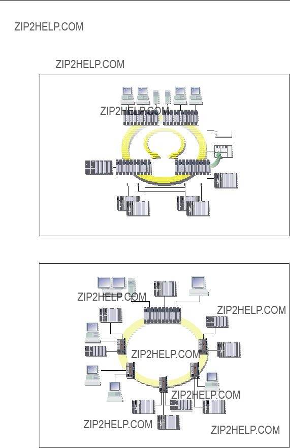
1.2.1Ring with Redundancy Manager
To increase the availability, optical or electrical line topologies of up to 50 switches (SCALANCE
Functional Description
With a SCALANCE
In contrast to the ring ports of the other switches, the ring ports of the redundancy manager are disconnected when the network is operating
In a ring with redundancy manager, there can only be one switch configured as a redundancy manager.
Connection of Other Network Segments or End Devices
At all ports of slots 9 to 11 or at the ports of a twisted pair extender module of the SCALANCE
The use of a media module extender in the redundancy manager and in all other switches in this network structure provides the option of connecting further end de- vices or complete subnets with FO cable.

Introduction to Industrial Ethernet Switches
Electrical Ring
A redundant electrical ring with redundancy manager can be set up without media modules since the basic device provides two
Optical Ring
An optical ring with redundancy manager is only possible with media modules. Which slots or ports should be used, depends on the selected transmission rate. The ports that can be used as ring ports are located on the media modules that can be used in slots 5, 6 and 7. As an alternative to optical gigabit transmission, the two ports on slot 6 or the first ports of slot 6 and 7 can be configured as ring ports for an optical fast Ethernet connection.
???Slot 5
equipped with
???Slot 6 / slot 6 and 7 (in each case only port 1)
equipped with
Introduction to Industrial Ethernet Switches
Configuration Example
Sample configurations with SCALANCE
SCALANCE 


 SCALANCE
RM


1000
Mbit/s
Figure
PC
PC
Fiber Optic
Figure

Introduction to Industrial Ethernet Switches
1.2.2Star Structure
Functional Description
Star structures can be implemented with the SCALANCE
Properties of a Star Structure
Each SCALANCE
Introduction to Industrial Ethernet Switches
Configuration Example
Sample configurations electrical / optical with SCALANCE
SCALANCE
Figure
Fiber Optic
Figure
Introduction to Industrial Ethernet Switches
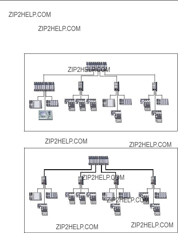
1.2.3Line Structure
Functional Description
Line structures can be implemented with the SCALANCE
Properties of the Line Structure
Each SCALANCE
Configuration Example
Sample configuration with SCALANCE
Fiber Optic
Figure

Introduction to Industrial Ethernet Switches
1.2.4Redundant Linking of Network Segments
The example of redundant linking of two network segments as shown here is pos- sible only when linking between X414 because the standby function of the X414 is required.
1000
Mbit/s
Figure
In this case, network segments are rings with a redundancy manager (RM). The rings can also be interrupted at one point (linear topology).
For a redundant link as shown in the figure, two devices must be configured within a network segment. This configuration is set in Web Based Management, Com- mand Line Interface or using SNMP access. For more detailed information, refer to the Configuration Manual SCALANCE

Introduction to Industrial Ethernet Switches
The two devices connected in the configuration exchange data frames with each other to synchronize their operating statuses (one device is master and the other slave). If there are no problems, only the link from the master to the other network segment is active. If this link fails (for example due to a
2.1Properties, Functionality and Features of SCALANCE
This chapter explains special properties, features and options available to you with the SCALANCE
The basic device consists of the frame, the power supply, digital inputs and a Switch CPU.
SCALANCE
???Gigabit technology
The basic device has ports with a transmission rate of 1 Gbps for electrical ca- bles (twisted pair) or by adding a gigabit media module for
???With SCALANCE
???Diagnostics
Remote diagnostic options are available with
???The basic device has a signaling contact for local operator control.
???An Ethernet interface is available for diagnostics and management purposes.

System Description of SCALANCE
???
When replacing a device, the
???VLAN
SCALANCE
???Spanning Tree / Rapid Spanning Tree
SCALANCE
System Description of SCALANCE
Components of SCALANCE
The following table shows the components of SCALANCE
For example
Media module extender Expands the basic device by four slots for fast Ethernet media modules.

System Description of SCALANCE
2.2Ports of SCALANCE
SCALANCE
2.2.1
Transmission Rate
The transmission rate of the electrical ports is 10 Mbps or as fast Ethernet ports 100 Mbps.
Transmission Mode
The transmission mode for
Autonegotiation (automatic detection of the best transmission modes) is standard. The order in which they are selected is:
???
???
???
???
Two communication modes are possible:
???Half duplex mode
???Full duplex mode

System Description of SCALANCE
Connections to other switches can use half or full duplex; connections to hubs are possible only in half duplex mode.
Transmission medium
Data transmission at 10 Mbps and at 100 Mbps is over two wire pairs (pin 1, 2, 3, 6) of the twisted pair cable. For 10 Mbps, at least a category 3 (Cat 3) and for 100 Mbps, at least a four wire cable (2x2) is necessary.
Transmission range
The maximum transmission distance (segment length) is 100 m.
Connectors
The connectors used are
The securing collar in conjunction with the cover ensures a flush fit and the locking mechanism with the

System Description of SCALANCE
2.2.2
Transmission Rate
The transmission rate of the electrical gigabit ports is 1 Gbps.
Transmission Mode
The transmission mode for
At 1 Gbps, autonegotiation is optional.
Two communication modes are possible:
???Half duplex
???Full duplex
Transmission Medium
Data is transmitted over an
Notice
For data transmission at 1 Gbps, at least Cat 5e
Transmission Range
The maximum transmission distance (segment length) is 100 m.
Connectors
The connectors used are

System Description of SCALANCE
2.2.3
Transmission Rate
The transmission rate of the optical fast Ethernet ports is 100 Mbps.
Transmission Mode
Transmission with
Transmission Medium
Data transmission is over multimode or single mode
Two FOC types can be used:
???Multimode FOC
The core diameter is 50 ??m; the light source is an LED. Many modes (light beams) are used for signal transmission. The propagation times of the light pulses (dispersion) restrict the maximum range considerably.
???Single mode FOC
The core diameter is 9 or 10 ??m; the light source is a laser diode. To transmit a signal, only one mode (light beam) is used greatly reducing dispersion. As a re- sult, the maximum range of single mode FOC is greater than that of multimode FOC.
Regardless of the type used, the outer diameter of the FOC is 125 ??m.

System Description of SCALANCE
Transmission Range
The maximum transmission range (segment length) depends on the module se- lected and the FOC. The range is as follows:
???
???
Connectors
BFOC connectors are used.

System Description of SCALANCE
2.2.4
Transmission Rate
The transmission rate of the optical gigabit ports is 1 Gbps.
Transmission Mode
Transmission with
Transmission Medium
Data is transmitted over multimode FOC. The wavelength is 850 nm.
The core diameter of the multimode FOC is 50 ??m; the light source is an LED. Many modes (light beams) are used for signal transmission. The propagation times of the light pulses (dispersion) restrict the maximum range considerably.
Transmission Range
The maximum transmission range (segment length) is 750 m when using SIMATIC NET
Connectors
SC duplex female connectors are used.

System Description of SCALANCE
2.2.5
Transmission Rate
The transmission rate of the optical gigabit ports is 1 Gbps.
Transmission Mode
Transmission with
Transmission Medium
Data is transmitted over single mode FOC. The wavelength is 1310 nm.
The core diameter of the single mode FOC is 9 or 10 ??m; the light source is a laser diode. To transmit a signal, only one mode (light beam) is used greatly reducing dispersion. As a result, the maximum range of single mode FOC is greater than that of multimode FOC.
Transmission Range
The maximum transmission range (segment length) is 10 km for single mode FOC.
Connectors
SC duplex female connectors are used.
System Description of SCALANCE
2.3Compatibility of SCALANCE
Compatibility List
The following products and devices are compatible with SCALANCE
???End devices
All SIMATIC NET products with a TP port can be connected to the ports of SCALANCE
???Network components in a line or star structure
-ESM/OSM
-OMC (TP cable max. 6 m long)
-SCALANCE
-SCALANCE
-SCALANCE
-SCALANCE
???Network components in a ring structure with SCALANCE
-ESM/OSM
-SCALANCE
-SCALANCE
???Redundant linking of 100 Mbps networks over FO cable.
The redundant optical linking of networks is allowed only with the devices ITP 53 with order number 6GK1
Note
All compatibility information assumes the correct use of the TP and FOC cables.

System Description of SCALANCE
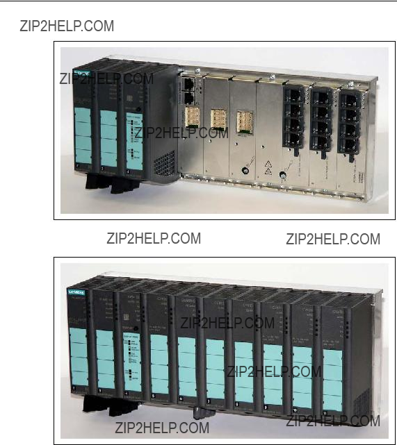
3.1SCALANCE
Overview
The SCALANCE
The SCALANCE
The integrated redundancy manager allows fast medium redundancy both for gi- gabit Ethernet and for fast Ethernet even in large networks.
To set up optical gigabit networks, both integrated gigabit Ethernet ports can be converted to
Product Description of SCALANCE
Figure
Figure

Product Description of SCALANCE
Components of the Product
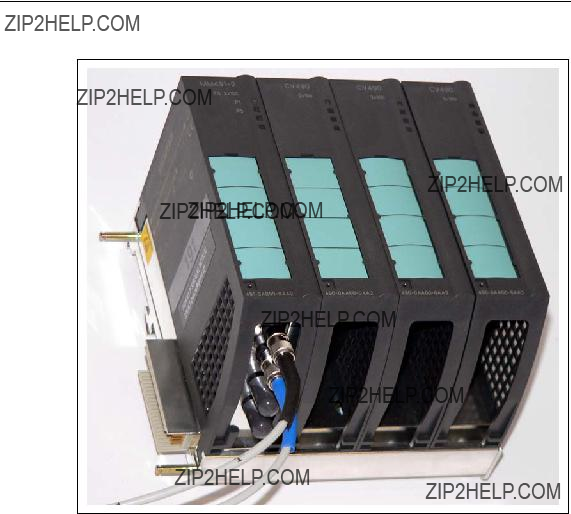
The following components are supplied with the SCALANCE
???Basic device with power module in slot 2, DI module with eight digital inputs in slot 3 Switch CPU including
Protective caps for media module terminal strips in slots 5, 6 and 7.
???1 CV490 2x1000, cover of media module slot 5
2 CV490 2x100, cover of media module slots 6 and 7 1 CV490 Cover, dummy cover for slot 8
3 CV490 4x100, cover for slots 9 to 11
???SIMATIC NET Manual Collection CD
???Slot labels for slots 1 through 18
???1 connector for power supply
???1 connector for signaling contact
???2 connectors for digital inputs
???1 sheet with 15 labeling strips

Product Description of SCALANCE
Spares
???1
???7 covers for slots (order number: 6GK5
-1 cover for slot 5 (1 Gbps - TP)
-2 covers for slots 6 and 7
-1 dummy cover for slot 8
-3 covers for slots 9 to 11 (100 Mbps - TP)
???Terminal set (order number: 6GK5
-10 connecting terminals for PS and signaling contact
-10 connecting terminals digital inputs
???1 location label (order number: 6ES7
???10 sheets of labels (A4) each with 15 labeling strips (order number: 6GK5
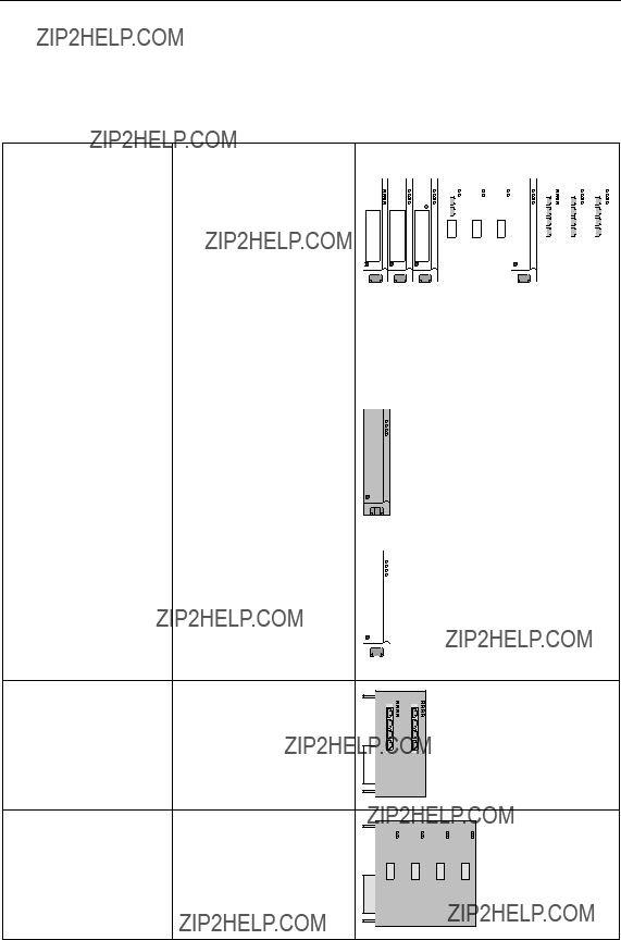
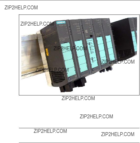
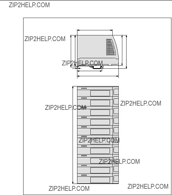
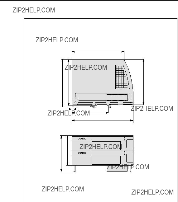
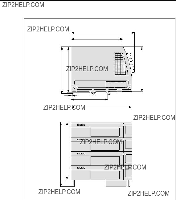
Slots
The SCALANCE
Figure

Product Description of SCALANCE
The modules in the individual slots have the following function (slot 1 is reserved for a power supply unit):
???Slot 2
Power module
The input voltage of 24 V DC is transformed to the internal supply voltage. The module has two
???Slot 3
Digital input module
The input module has two
???Slot 4
CPU module
-Contains the processor that provides the management functionality.
-
-DIL switch for the redundancy manager function and to specify the ring ports.
-SELECT/SEL button for switching over the display modes, for resetting to the factory default settings and to define the fault mask.
-LED display of the display modes DMode A through DMode D.
???Slot 5
Contains two
As an option, slot 5 allows the use of an optical gigabit module with two ports
???Slots 6 and 7
Optional use of two optical fast Ethernet modules (100 Mbps) each with two ports
???Slot 8
No function in system.
???Slot 9 through 11
Each contains four
These cannot be used by media modules.
Product Description of SCALANCE
The basic version of the SCALANCE
Figure
By inserting media modules in slots 6 and 7, you have 4 further optical ports avail- able either as ring ports or as end device ports.
By docking an extender module to the right of slot 11, you can extend the basic device by a further 8 ports. There are two types of extender available, one for twisted pair ports and one for
Product Description of SCALANCE
3.1.1Power Module
The power module is inserted in slot 2.
The power can be fed into the power module redundantly over two inputs. The two power inputs are isolated from each other, there is no power distribution. If redun- dant power
The front
Figure

Product Description of SCALANCE
Signaling Contact
The following can be signaled over a floating signaling contact:
???Failure of the power supply.
The power supply monitored is selected in the fault mask.
???Bad link status of a port.
(wrong connector or no connection to partner device). The port monitored is se- lected in the fault mask.
???Change to the DIL switch during operation.
Possible inconsistency between the switch setting and the actual operating state, The switch setting is adopted only after a restart.
If the SCALANCE
???Bad link status of the ring ports, regardless of the status of the fault mask.
???Configuration of a second SCALANCE
Product Description of SCALANCE
3.1.2Digital Inputs
DI Module
The digital input module is located in slot 3 and provides the user with eight digital inputs. The cables are connected to the bottom of the module by two
Figure
Depending on the configuration, the states of the digital inputs can be used to send
It is also possible to read the statuses over SNMP.
Product Description of SCALANCE
3.1.3Switch CPU
The Switch CPU is in slot 4.
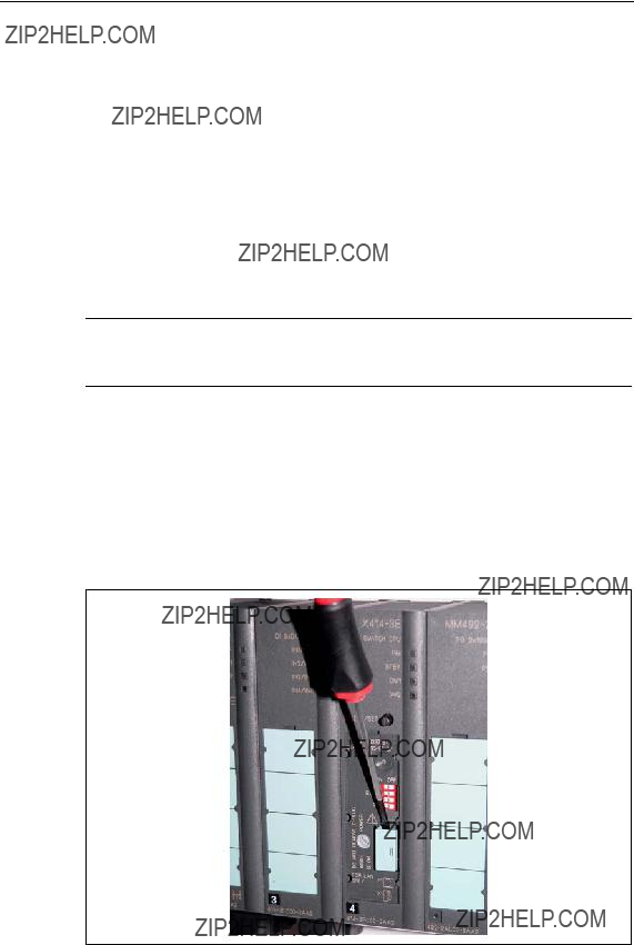
The CPU has four DIL switches for configuring the device. This module also has four LEDs for displaying parameter assignments that can be modified by the user with the DIL switch and a SELECT / SET button.
Figure
Product Description of SCALANCE
Serial Port
The Switch CPU of the SCALANCE
???Firmware updates
???Management with the aid of the command interpreter (Command Line Inter- preter, CLI) including setting of the IP address information.
Input to the command interpreter is over command lines.
For more detailed information, refer to the SCALANCE
Pin1
Pin6
Pin7
Pin2RD
Pin3TD
Pin8
Pin4
Pin9
Ethernet Port
Pin5SG
On the bottom panel of the SCALANCE
???Configuration
???Commissioning
The SCALANCE
For more detailed information, refer to the SCALANCE

Product Description of SCALANCE
3.1.4
Area of Application
The
Notice
The
How It Works
Power is supplied by the basic device. The
If an empty

Product Description of SCALANCE
A device with an accepted
This allows a basic device to be replaced quickly and simply. The
Notice
If the SCALANCE
Diagnostics
Inserting a

Product Description of SCALANCE
Startup Behavior
In cases 1 and 2, the configuration data on the Switch CPU and the
Notice
In case 4 (replacing the switch), the DIL switch settings of the
For more detailed information, refer to the SCALANCE

Product Description of SCALANCE
3.1.5Ports
The SCALANCE
Figure
Figure

Product Description of SCALANCE
4.1Media Modules
Available Module Types
The following media modules are available to expand the basic device:
???
order number: 6GK5
???
order number: 6GK5
???
order number: 6GK5
???
order number: 6GK5
By using media modules, you can increase the number of available ports in the basic device SCALANCE
Media Modules, Covers, Dummy Cover
Note
It is possible to insert and remove the media modules during operation. Before inserting a media module, remove the cover and cap from the slot. Please put these away for safe keeping. If you remove a media module, close the the terminal strip with the cap and and the slot with the cover.
Options for Slot 5
Slot 5 of the basic device has two
Options for Slots 6 and 7
Slots 6 and 7 do not have any ports but allow two optical fast Ethernet modules to be inserted each with ports. This gives you the opportunity of data transmission at a data transmission rate of 100 Mbps over multimode or single mode FOC.
Figure
Media Modules, Covers, Dummy Cover
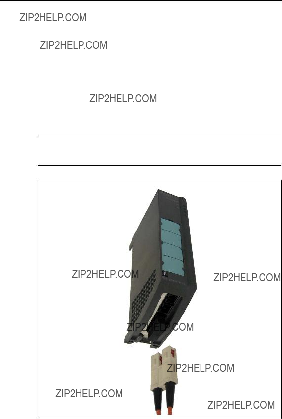
4.1.1Fast Ethernet Media Module
The fast Ethernet media module
Properties
The fast Ethernet media module provides two ports for connecting the multimode FOC. The signal is transmitted by LED with a wavelength of 1310 nm. The maxi- mum cable length is 3 km.
Connector
The connectors are 2x2 BFOC sockets.
LED Display of the Fast Ethernet Media Module
The LED displays of the module are the same as the LEDs of the basic device. With optical transmission, a fixed transmission rate of 100 Mbps and full duplex mode is set. The display in display modes B and C is analogous.
???In display mode A, the current connection status is displayed.
???In display mode B, the fixed transmission rate is displayed.
???In display mode C, the full duplex mode is displayed.
???In display mode D, you can see whether or not the port is monitored.
Figure
Media Modules, Covers, Dummy Cover
4.1.2Fast Ethernet Media Module
The fast Ethernet media module
Properties
The fast Ethernet media module provides two ports for connecting the single mode FOC. The signal is transmitted by laser diode with a wavelength of 1310 nm. The maximum cable length is 26 km.
Connector
The connectors are 2x2 BFOC sockets.
LED Display of the Fast Ethernet Media Module
The LED displays of the module are the same as the LEDs of the basic device. With optical transmission, only a fixed transmission rate and full duplex mode are possible. The display in display modes B and C is analogous.
???In display mode A, the current connection status is displayed.
???In display mode B, the fixed transmission rate is displayed.
???In display mode C, the full duplex mode is always displayed.
???In display mode D, you can see whether or not the port is monitored.
Figure

Media Modules, Covers, Dummy Cover
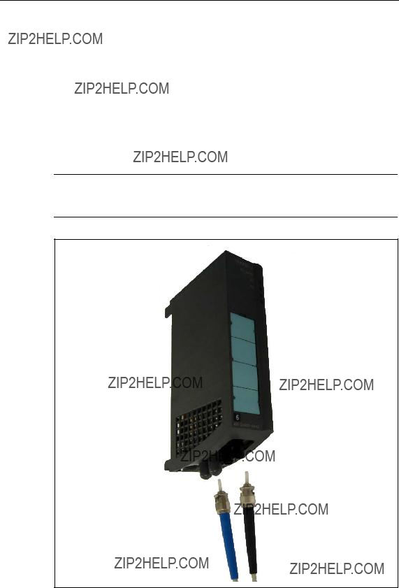
4.1.3Gigabit Media Module
The
Properties
The gigabit media module provides two ports for connecting the multimode FOC. The signal is transmitted using an LED at a wavelength of 850 nm. Both ports of the module can be configured as ring ports. The maximum cable length is 750 m when using SIMATIC NET
Connector
SC duplex female connectors are used.
LED Display of the Gigabit Media Module
The LED displays of the module are the same as the LEDs of the basic device. With optical transmission, only a fixed transmission rate and full duplex mode are possible. The display in display modes B and C is analogous.
???In display mode A, the current connection status is displayed.
???In display mode B, the fixed transmission rate is displayed.
???In display mode C, the full duplex mode is always displayed.
???In display mode D, you can see whether or not the port is monitored.
Figure

Media Modules, Covers, Dummy Cover
4.1.4Gigabit Media Module
The
Properties
The media module provides two ports for connecting the single mode FOC. Signal transmission uses a laser diode at a wavelength of 1310 nm. Both ports of the module can be configured as ring ports. The maximum cable length is 10 km when using SIMATIC NET
Connector
SC duplex female connectors are used.
LED Display of the Gigabit Media Module
The LED displays of the module are the same as the LEDs of the basic device. With optical transmission, only a fixed transmission rate and full duplex mode are possible. The display in display modes B and C is analogous.
???In display mode A, the current connection status is displayed.
???In display mode B, the fixed transmission rate is displayed.
???In display mode C, the full duplex mode is always displayed.
???In display mode D, you can see whether or not the port is monitored.
Figure

Media Modules, Covers, Dummy Cover
4.2Covers, Dummy Cover
4.2.1Covers
Slots of the Covers
Note
The protective caps for the media module terminal strips and the covers must be fitted in all slots that do not contain media modules.
For slots for twisted pair (9 through 11), the covers are recommended to protect the
Figure
Available Cover Types
To cover slots not used for media modules or slots for twisted pair, the following types of cover are available:
???CV490 2x1000
???CV490 2x100
???CV490 4x100

Media Modules, Covers, Dummy Cover
CV490 2x1000
When using the gigabit ports for electrical cables (twisted pair), use cover type CV490 2x1000 on slot 5.
Figure
Displays of the Cover
The port status of the two electrical gigabit ports 1 and 2 are displayed on the front panel of the cover by two LEDs.

Media Modules, Covers, Dummy Cover
CV490 2x100
Slots 6 and 7 are solely for the fast Ethernet media modules
Figure
Displays of the Cover
The LEDs of the CV490 2x100 cover have no function.
Further Slots for the CV490 2x100 Cover
Use the CV490 2x100 cover not only for the SCALANCE
Figure

Media Modules, Covers, Dummy Cover
CV490 4x100
The SCALANCE
Figure
Displays of the Cover
The status of each of the four fast Ethernet ports 1 through 4 is displayed on the front panel of the CV490 4x100 cover by four LEDs.
Further Slots for the CV490 4x100 Cover
The CV490 4x100 cover can not only be used with the SCALANCE
Figure

Media Modules, Covers, Dummy Cover
4.2.2Dummy Cover
Slot of the Dummy Cover
The dummy cover with the name CV490 COVER is located in slot 8 of the SCALANCE
Figure
Displays of the Dummy Cover
The LEDs of the dummy cover have no function and there is therefore no port in- formation on the front panel of the dummy cover.

Media Modules, Covers, Dummy Cover
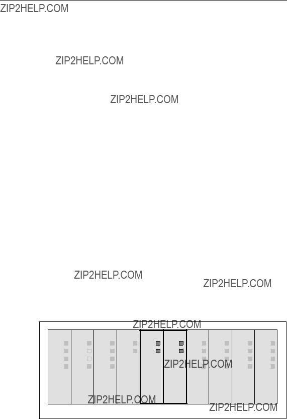
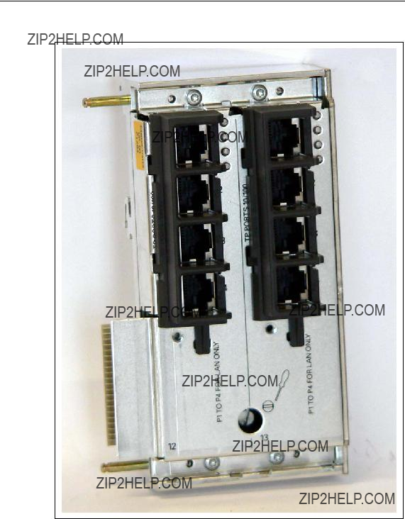
5.1Twisted Pair Extender
Eight Additional
The extender module for twisted pair transmission provides an additional eight ports for connecting twisted pair cables. The TP cable is attached to an
Note
The twisted pair extenders can also be installed during operation.
The transmission rate of the Ethernet ports is 10 Mbps or as a fast Ethernet port 100 Mbps. No media module is required for data transfer with this extender mod- ule.
Figure
Extender Modules
Figure
Covers
For slots 12 and 13 of the twisted pair extenders

Extender Modules
5.2Media Module Extender
Four Additional Slots for Media Modules
By adding the media module extender, the basic device is extended by four slots that you can equip with the following modules as required:
???
???
If you use all slots, you have an additional eight optical fast Ethernet ports available (100 Mbps).
Note
Installation of the media module extender and removal or insertion of the media modules is possible during operation.
You require at least one media module for data transfer over this extender module.
Mixed operation in slots 12 through 15 with
Connector
The connectors are 2x2 BFOC sockets.
Figure

Extender Modules
Figure
Covers
Four CV490 2x100 covers are supplied with the media module extender
Extender Modules
Figure

Extender Modules
6.1Installing / Removing the SCALANCE
!Warning
SCALANCE
The power supply unit for the 24 V DC supply must comply with NEC Class 2 (voltage range 20.4 - 28.8 V DC, current requirement max. 2 A). If the device is supplied with power redundantly, both power supply units together must comply with NEC Class 2.
Exceptions:
???Power supply with PELV (according to VDE
???Power supply by a SELV power source (according to IEC 60950) or PELV power source (according to VDE
-Installation in a cabinet or suitable enclosure
-Installation in a suitably equipped, closed room
!Caution
The subject unit must be located in a Restricted Access Location where access can only be gained by SERVICE PERSONNEL or by USERS who have been in- structed about the reasons for the restrictions applied to the location and about any precautions that shall be taken when operated in an air ambient of 50??C - 60??C

Installation and Commissioning
6.1.1Installing / Uninstalling with an
Installing on an
For installation, you require a slotted screwdriver with a 5.5 mm wide blade.
Notice
When installing the SCALANCE
To install the device, follow the steps below:
1.Tilt the basic device slightly towards the back with the upper groove on the edge of the
2.Remove the covers from slots 7 and 9 (see section 6.2.2) and the dummy cover from slot 8 (see section 6.2.3). If media modules are inserted, remove the fast Ethernet media module instead of the cover from slot 7 (see section 6.2.1).
3.Using a screwdriver with a 5.5 mm wide blade, tighten the two captive screws in the backplane at slot 7 and between slots 8 and 9 until the basic device can no longer be moved to the side.
Note
Only horizontal installation permitted (ventilation slit top/bottom).
Installation and Commissioning
Figure
Removing from the
To remove the device, you require a slotted screwdriver with a 5.5 mm wide blade.
Notice
When removing the SCALANCE
To remove the device, follow the steps below:
1.Remove the covers from slots 7 and 9 (see section 6.2.2) and the dummy cover from slot 8 (see section 6.2.3). If media modules are inserted, remove the fast Ethernet media module instead of the cover from slot 7 (see section 6.2.1).
2.Using a screwdriver with a 5.5 mm wide blade, loosen the two captive screws in the backplane at slot 7 and between slots 8 and 9.
3.Pull out the lower part of the basic device slightly towards the front and lift it from the
Installation and Commissioning
6.1.2Installing / Uninstalling with a 35 mm Standard Rail
Installation on a 35 mm Standard Rail
!Caution
If the SCALANCE
Since the two captive screws in slot 7 and between slots 8 and 9 are not used to secure the device when installing on a 35 mm standard rail, it is not absolutely nec- essary to remove the covers and the blind cover, although this does make it easier to handle the basic device.
Notice
When installing the SCALANCE
To install the device, follow the steps below:
1.Place the central groove containing two spring clips on the back of the basic device on the upper edge of the standard rail with the device tilted slightly to- wards the back. Make sure that the two spring clips are located behind the edge and are visible from the rear of the installation frame.
2.Press the basic device down and push in the lower part until you hear it click into place in the standard rail.
3.Adjust the basic device to the right or left until it is in the required position.
Note
Only horizontal installation permitted (ventilation slit top/bottom).
Installation and Commissioning
Figure
Removing from the 35 mm Standard Rail
Since the two captive screws in slot 7 and between slots 8 and 9 are not used to secure the device, when removing it from a 35 mm standard rail, it is not absolutely necessary to remove the covers and the blind cover, although this does make it easier to handle the basic device.
Notice
When removing the SCALANCE
To remove the device, follow the steps below:
1.Push the basic device down until the lower part can be pulled away from the standard rail to the front.
2.Lift the SCALANCE

Installation and Commissioning
6.2Installing / Removing the Media Modules, Covers and Dummy Cover
6.2.1Installing / Removing a Media Module
Installing a Media Module
For installation, you require a slotted screwdriver with a 2.8 mm wide blade.
Note
Installing a fast Ethernet media module is the same in the SCALANCE
1.Remove the cover (see section 6.2.2) from the slot of the media module and remove the protective cap from the module terminal strip from the backplane of the basic device.
Note
Keep these parts in a safe place in case you want to remove the media mod- ule later.
2.Remove the inserted labeling strip from the front of the media module.
3.Place the two lower guides of the media module into the recesses at the lower edge of the basic device. It should no longer be possible to move the media module to the side.
4.Tilt the media module at an angle towards the back until the two plastic pins at the back top edge of the media module jut into the recesses in the basic de- vice. The terminal strip of the media module must fit into the guide in the back- plane.
5.Press the upper part of the media module onto the basic device until the fluted middle section of the media module is heard to click into place.
6.Tighten the captive screw on the front of the media module with a slotted screwdriver with a 2.8 mm wide blade.
7.Secure the labeling strip on the front of the media module.
Installation and Commissioning
Figure
Removing a Media Module
To remove the device, you require a slotted screwdriver with a 2.8 mm wide blade.
Note
Removing a fast Ethernet media module is the same in the SCALANCE
1.Remove the inserted labeling strip from the front of the media module.
2.Release the captive screw on the front of the media module as far as it will go with a slotted screwdriver with a 2.8 mm wide blade.
3.Press on the fluted middle section of the top of the media module next to the backplane.
4.At the same time, tilt the media module down at an angle, the two guides ini- tially remain in the recesses at the lower edge of the basic device.
5.Remove the media module by pulling it upwards.
6.Fit the protective cap on the module terminal strip on the backplane of the ba- sic device. Fit the appropriate cover (see section 6.2.2) to the slot of the media module.

Installation and Commissioning
6.2.2Fitting / Removing the Covers
Variants of the Covers
There are three variants of the covers
???CV490 2x1000
1 Gbps, electrical transmission, 2 port displays possible slot: 5
???CV490 2x100
4 blind displays (no port displays connected to front)
possible slots: 6, 7 and extender module
???CV490 4x100
10/100 Mbps, electrical transmission, 4 port displays
possible slots: 9 through 11 and extender module
Fitting a Cover
To fit a cover, you do not require any tools.
1.Place the two lower guides of the cover into the recesses at the lower edge of the basic device. It should no longer be possible to move the cover to the side.
2.Tilt the cover at an angle towards the back until the two plastic pins at the back top edge of the cover jut into the recesses in the basic device.
3.Press the upper part of the cover onto the basic device until the fluted middle section of the cover is heard to click into place.
4.Secure the labeling strip on the front of the cover.
Removing a Cover
To remove a cover, you do not require any tools.
1.Press on the fluted middle section of the top of the cover next to the backplane.
2.At the same time, tilt the cover down at an angle, the two guides initially remain in the recesses at the lower edge of the basic device.
3.Remove the cover by pulling it upwards.

Installation and Commissioning
6.2.3Fitting / Removing a Dummy Cover
Fitting a Dummy Cover
There is only one dummy cover (no port displays connected to the front) on slot 8.
To fit a cover, you do not require any tools.
1.Place the two lower guides of the dummy cover into the recesses at the lower edge of the basic device. It should no longer be possible to move the dummy cover to the side.
2.Tilt the dummy cover at an angle towards the back until the two plastic pins at the back top edge of the dummy cover jut into the recesses in the basic device.
3.Press the upper part of the dummy cover onto the basic device until the fluted middle section of the dummy cover is heard to click into place.
4.Secure the labeling strip on the front of the dummy cover.
Removing a Dummy Cover
To remove a cover, you do not require any tools.
1.Press on the fluted middle section of the top of the dummy cover next to the backplane.
2.At the same time, tilt the dummy cover down at an angle, the two guides ini- tially remain in the recesses at the lower edge of the basic device.
3.Remove the dummy cover by pulling it upwards.

Installation and Commissioning
6.3Installing / Removing Extender Modules
6.3.1Installing / Removing the Twisted Pair Extender
Installing the Twisted Pair Extender on the
You require the following tools:
???slotted screwdriver with a 2.8 mm wide blade
???slotted screwdriver with a 5.5 mm wide blade
Note
Make sure that in addition to the extender width of 87 mm, there is a clearance of 20 mm to the right of the basic device on the
When installing a twisted pair extender on an
1.Remove the cover from slot 11 of the basic device.
2.Remove the
3.Remove the side panel of the basic device from the basic device to the right.
Note
Keep the panel in a safe place in case the extender needs to be removed again later.
4.Remove the two covers from the extender.
5.Place the extender module on the edge of the

Installation and Commissioning
6.Push the extender module slowly to the left while keeping it straight and with- out skewing and check that the two guide bolts on the extender fit into the holes in the basic device. Then push the extender module to the left as far as it will go so that it is flush with the right side of the basic device.
7.Using a slotted screwdriver with a 5.5 mm wide blade, tighten the captive screw between slots 12 and 13 in the lower part of the extender module.
8.Using a slotted screwdriver with a 2.8 mm wide blade, tighten the two captive slug screws on slot 11. The screws lock the two guide bolts, so do not use ex- cessive force when tightening them.
9.Fit the CV490 4x100 cover to slot 11 of the basic device and slots 12 and 13 of the twisted pair extender.
Figure

Installation and Commissioning
Removing the Twisted Pair Extender from the
You require the following tools:
???slotted screwdriver with a 2.8 mm wide blade
???slotted screwdriver with a 5.5 mm wide blade
When removing a twisted pair extender from an
1.To remove an extender module, remove the two covers on the extender.
2.Using a slotted screwdriver with a 5.5 mm wide blade, open the captive screw between slots 12 and 13 in the lower part of the extender module.
3.Remove the cover from slot 11 of the basic device.
4.Use a slotted screwdriver with a 2.8 mm wide blade to loosen the two captive slug screws on slot 11 of the basic device in the upper and lower recesses as far as they will go.
5.Push the extender module slowly to the right while keeping it straight until the two guide bolts of the extender module are completely outside the holes in the basic device.
6.Pull out the lower part of the extender module slightly towards the front and lift it from the
7.Replace the right side panel of the basic device so that the guide bolts fit into the two holes in the basic device.
8.Using a slotted screwdriver with a 2.8 mm wide blade, tighten the two captive slug screws on slot 11. The screws lock the two guide bolts, so do not use ex- cessive force when tightening them.
9.Fit a suitable cover on slot 11 of the basic device.
Note
The basic device must not be used permanently without the right side panel.

Installation and Commissioning
Installing the Twisted Pair Extender on the 35 mm Standard Rail
!Caution
If the SCALANCE
For installation, you require a slotted screwdriver with a 2.8 mm wide blade.
Although the captive screw in the lower part between slots 12 and 13 of the ex- tender module is not used when installing on a 35 mm standard rail, it is neverthe- less advisable to remove the media modules.
Note
Make sure that in addition to the extender width of 87 mm, there is a clearance of
20mm to the right of the basic device on the 35 mm standard rail to be able to align the guide bolts of the extender with the holes in the basic device during installation.
When installing a twisted pair extender on a 35 mm standard rail, the basic device remains in position. Follow the steps below:
1.Remove the cover from slot 11 of the basic device.
2.Remove the
3.Remove the side panel of the basic device from the basic device to the right.
Note
Keep the panel in a safe place in case the extender needs to be removed again later.
4.Place the central groove containing a spring clip on the back of the extender module on the upper edge of the 35 mm standard rail with the module tilted slightly towards the back. Make sure that there is adequate clearance between the guide bolts of the extender module and the basic device.
5.The spring clip must be located behind the edge of the standard rail so that it is visible from the rear of the frame.
Installation and Commissioning
6.Press the extender module down and push in the lower part until you hear it click into place in the 35 mm standard rail.
7.Push the extender module slowly to the left while keeping it straight and with- out skewing and check that the two guide bolts on the extender fit into the holes in the basic device. Then push the extender module to the left as far as it will go so that it is flush with the right side of the basic device.
8.Using a slotted screwdriver with a 2.8 mm wide blade, tighten the two captive slug screws on slot 11. The screws lock the two guide bolts, so do not use ex- cessive force when tightening them.
9.Fit the CV490 4x100 cover to slot 11 of the basic device and slots 12 and 13 of the twisted pair extender.
Figure
Installation and Commissioning
Removing the Twisted Pair Extender from the 35 mm Standard Rail
To remove the device, you require a slotted screwdriver with a 2.8 mm wide blade.
The captive screw in the lower part of the extender module between slot 12 and 13 is not used for mounting on an 35 mm standard rail. When removing a twisted pair extender from a 35 mm standard rail, the basic device remains in position. Follow the steps below:
1.Remove the cover from slot 11 of the basic device.
2.Use a slotted screwdriver with a 2.8 mm wide blade to loosen the two captive slug screws on slot 11 of the basic device in the upper and lower recesses as far as they will go.
3.Push the extender module slowly to the right while keeping it straight until the two guide bolts of the extender module are completely outside the holes in the basic device.
4.Push the twisted pair extender down until the lower part can be pulled away from the standard rail to the front.
5.Lift the extender module up and off the 35 mm standard rail.
6.Replace the right side panel of the basic device so that the guide bolts fit into the two holes in the basic device.
7.Using a slotted screwdriver with a 2.8 mm wide blade, tighten the two captive slug screws on slot 11. The screws lock the two guide bolts, so do not use ex- cessive force when tightening them.
8.Fit a suitable cover on slot 11 of the basic device.
Note
The basic device must not be used permanently without the right side panel.

Installation and Commissioning
6.3.2Installing / Removing the Media Module Extender
Installing the Media Module Extender on the
You require the following tools:
???slotted screwdriver with a 2.8 mm wide blade
???slotted screwdriver with a 5.5 mm wide blade
Note
Make sure that in addition to the extender width of 155 mm, there is a clearance of 20 mm to the right of the basic device on the
Note
Protective caps and CV490 2x100 covers must be fitted to all slots without media modules.
When installing a media module extender on an
1.Remove the cover from slot 11 of the basic device.
2.Remove the
3.Remove the side panel of the basic device from the basic device to the right.
Note
Keep the panel in a safe place in case the extender needs to be removed again later.
4.Remove the four covers from the extender.
5.Place the extender module on the edge of the
Installation and Commissioning
6.Push the extender module slowly to the left while keeping it straight and with- out skewing and check that the two guide bolts on the extender fit into the holes in the basic device. Then push the extender module to the left as far as it will go so that it is flush with the right side of the basic device.
7.Using a slotted screwdriver with a 5.5 mm wide blade, tighten the captive screw between slots 13 and 14 in the lower part of the extender module.
8.Using a slotted screwdriver with a 2.8 mm wide blade, tighten the two captive slug screws on slot 11. The screws lock the two guide bolts, so do not use ex- cessive force when tightening them.
9.Fit the CV490 4x100 cover on slot 11 of the basic device. Make sure that the media module terminal strips of slots not occupied by media modules have protective caps fitted and that the CV490 2x100 covers are in place.
Figure

Installation and Commissioning
Removing the Media Module Extender from the
You require the following tools:
???slotted screwdriver with a 2.8 mm wide blade
???slotted screwdriver with a 5.5 mm wide blade
Note
To remove the extender, remove the media modules from slots 13 and 14.
When removing a media module extender from an
1.To remove an extender module, use a slotted screwdriver with a 5.5 mm wide blade, to open the captive screw between slots 13 and 14 in the lower part of the extender module.
2.Remove the cover from slot 11 of the basic device.
3.Use a slotted screwdriver with a 2.8 mm wide blade to loosen the two captive slug screws on slot 11 of the basic device in the upper and lower recesses as far as they will go.
4.Push the extender module slowly to the right while keeping it straight until the two guide bolts of the extender module are completely outside the holes in the basic device.
5.Pull out the lower part of the extender module slightly towards the front and lift it from the
6.Replace the right side panel of the basic device so that the guide bolts fit into the two holes in the basic device.
7.Using a slotted screwdriver with a 2.8 mm wide blade, tighten the two captive slug screws on slot 11. The screws lock the two guide bolts, so do not use ex- cessive force when tightening them.
8.Fit a suitable cover on slot 11 of the basic device.
Note
The basic device must not be used permanently without the right side panel.

Installation and Commissioning
Installing the Media Module Extender on the 35 mm Standard Rail
!Caution
If the SCALANCE
For installation, you require a slotted screwdriver with a 2.8 mm wide blade.
Although the captive screw in the lower part between slots 13 and 14 of the ex- tender module is not used when installing on a 35 mm standard rail, it is neverthe- less advisable to remove the media modules.
Note
Make sure that in addition to the extender width of 155 mm, there is a clearance of
20mm to the right of the basic device on the 35 mm standard rail to be able to align the guide bolts of the extender with the holes in the basic device during installation.
Note
Protective caps and CV490 2x100 covers must be fitted to all slots without media modules.
When installing a media module extender on a 35 mm standard rail, the basic de- vice remains in position. Follow the steps below:
1.Remove the cover from slot 11 of the basic device.
2.Remove the
3.Remove the side panel of the basic device from the basic device to the right.
Note
Keep the panel in a safe place in case the extender needs to be removed again later.
4.Place the central groove containing a spring clip on the back of the extender module on the upper edge of the 35 mm standard rail with the module tilted slightly towards the back. Make sure that there is adequate clearance between the guide bolts of the extender module and the basic device.
Installation and Commissioning
5.The spring clip must be located behind the edge of the 35 mm standard rail so that it is visible from the rear of the frame.
6.Press the extender module down and push in the lower part until you hear it click into place in the standard rail.
7.Push the extender module slowly to the left while keeping it straight and with- out skewing and check that the two guide bolts on the extender fit into the holes in the basic device. Then push the extender module to the left as far as it will go so that it is flush with the right side of the basic device.
8.Using a slotted screwdriver with a 2.8 mm wide blade, tighten the two captive slug screws on slot 11. The screws lock the two guide bolts, so do not use ex- cessive force when tightening them.
9.Fit the CV490 4x100 cover on slot 11 of the basic device. Make sure that the media module terminal strips of slots not occupied by media modules have protective caps fitted and that the CV490 2x100 covers are in place.
Figure

Installation and Commissioning
Removing the Media Module Extender from the 35 mm Standard Rail
To remove the device, you require a slotted screwdriver with a 2.8 mm wide blade.
Although the captive screw in the lower part between slots 13 and 14 of the ex- tender module is not used on a 35 mm standard rail, it is nevertheless advisable to remove the media modules. When removing a media module extender from a 35 mm standard rail, the basic device remains in position. Follow the steps below:
1.Remove the cover from slot 11 of the basic device.
2.Use a slotted screwdriver with a 2.8 mm wide blade to loosen the two captive slug screws on slot 11 of the basic device in the upper and lower recesses as far as they will go.
3.Push the extender module slowly to the right while keeping it straight until the two guide bolts of the extender module are completely outside the holes in the basic device.
4.Push the media module extender down until the lower part can be pulled away from the standard rail to the front.
5.Lift the extender module up and off the 35 mm standard rail.
6.Replace the right side panel of the basic device so that the guide bolts fit into the two holes in the basic device.
7.Using a slotted screwdriver with a 2.8 mm wide blade, tighten the two captive slug screws on slot 11. The screws lock the two guide bolts, so do not use ex- cessive force when tightening them.
8.Fit a suitable cover on slot 11 of the basic device.
Note
The basic device must not be used permanently without the right side panel.
Installation and Commissioning
6.4Slot Numbers of the Modules and Covers
Specifying the Slot Number
The three preinstalled modules, the media modules, the covers for unused slots and the dummy cover for slot 8 must be labeled with the slot number using the slot number tabs supplied. Since the power supply unit is not located on the basic de- vice and has slot number 1, start with number 2 for the power module. The order for the other modules is in ascending order to the right. The applies to any ex- tender modules that may be used, starting from the left with number 12.
Applying the Slot Numbers
1.Place the required slot number in front of the module.
2.Place the tongue in the opening on the module.
3.Press the slot number into the recess on the front of the housing with your fin- ger. The slot number breaks out of the wheel.
16
15
 14
14
13
2 1
3
4
 5
5
6
7

Installation and Commissioning
6.5Factory Defaults
DIL Switches
When supplied, the four DIL switches on the switch are set to OFF as default.
Notice
Before starting up for the first time, check the switch settings.
???RM
is set to OFF. This means that the redundancy manager function is disabled.
???STBY
is set to OFF. This switch is intended for future applications and is does not cur- rently have any function.
???R1, R2
are set to OFF. Both (electrical) gigabit ports on slot 5 are defined as ring ports.
Further Device Properties
With R1 and R2, ring redundancy is enabled when the device ships.
Notice
In this mode, RSTP / STP cannot be activated.
When delivered, the
Installation and Commissioning
6.6Ports
6.6.1Power Supply Connectors (X1)
Polarity Reversal Protection X1, X2
The two
The redundant power supply is connected over a
X1
X2
L2 M2 M1 L1
Figure
Installation and Commissioning
6.6.2Connectors of the Signaling Contact and Grounding Strap (X2)
The signaling contact is connected by contacts MK1 and MK2 on the
X1
X2
MK2 GND M3 MK1
Figure
By inserting a strap between protective earth P and M3, the SCALANCE
When the device ships, no strap is fitted
Installation and Commissioning
6.6.3Digital Input Connectors (X1)
Polarity Reversal Protection X1, X2
The two
Digital inputs 1 through 4 are connected using a
!Warning
The input voltage must not exceed + 30 V and must not fall below ??? 30 V, other- wise the DI module will be destroyed.

Installation and Commissioning
6.6.4Digital Input Connectors (X2)
Digital inputs 5 through 8 are connected using a
X1
X2
IN8 IN7 M5 IN6 IN5
Figure
Installation and Commissioning
6.6.5Connectors for the Twisted Pair Cables
The FastConnect Cabling System
With the IE FC
Two FastConnect cable types are available, the
The diameter of the IE FC standard cable 4x2 does not allow connection to an RJ- 45 plug so that only the IE FC standard cable 2x2 as a
The flexible
Figure
ATP cord (1 Gbps)
BIE FC Standard Cable 2x2 (100 Mbps)
Installation and Commissioning
Connecting TP Cord to FC Cable
To connect TP Cord to FC cables, two IE FC
???IE FC
1
???IE FC
2
With the IE FC
Figure

Installation and Commissioning
With the IE FC
Figure

Installation and Commissioning
The maximum segment length of 100 m also applies when using the FastConnect cabling with TP cord. Normally, FastConnect cable with a length of 90 m is used. The remaining 10 m is then available for TP cord at both ends (total of 10 m).
B A2 A2
IEFCRJ45Modular
OutletInsert2FE
B A2
A2
IEFCRJ45Modular
OutletInsert1GE
A1+A2=10m
A1+B+A2=100m
Installation and Commissioning
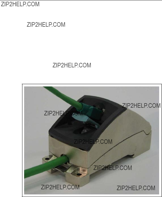
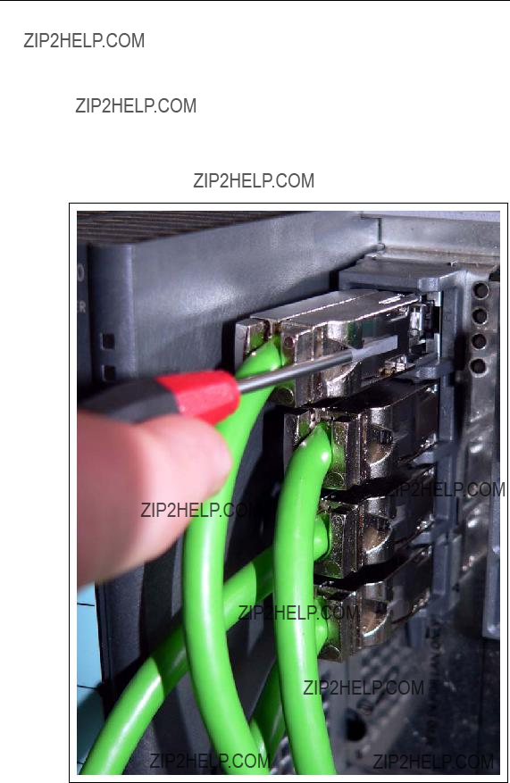
Removing the FC Cable from SCALANCE
Under some circumstances, a screwdriver is necessary to remove the twisted pair cables with
1.Press the catch on the
2.Remove the cable.
Figure
Installation and Commissioning
6.6.6Connectors for
Gigabit Transmission with FOC
Data transmission at 1 Gbps is over multimode FOC or single mode FOC. In both cases, the
When a media module is inserted, port 1 is to the front and port 2 to the rear.
Notice
Figure
Installation and Commissioning
Fast Ethernet Transfer with FOC
Data transmission at 100 Mbps is over multimode FOC or single mode FOC. In both cases, the BFOC plug on the
When a media module is inserted, the two front sockets belong to port 1 and the two rear sockets to port 2. The front socket is the input and the rear socket is the output socket of the particular port. Behind the labeling strip on the front of the me- dia module, you will see the relevant symbols.
Notice
Figure
Installation and Commissioning
6.7Operator Controls
6.7.1DIL Switches
Below the labeling strip on the Switch CPU, on slot 4, there are four DIL switches. These DIL switches can have one of two states (ON / OFF).
Figure

Installation and Commissioning
Notice
Changing the switch settings during operation causes fault displays and activates the signaling contact. The settings are adopted only after the device is restarted.
The RM switch allows you to configure the SCALANCE
The STBY switch is reserved for future functionality and does not currently have any function.
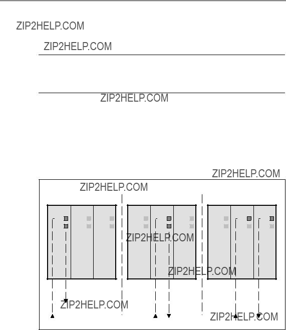
With switches R1 and R2, you can specify either the two ports in slot 5, the two ports in slot 6 or the first ports of slots 6 and 7 as ring ports. If you do not want any ring ports defined, both switches must be set to ON.
When shipped, the factory settings apply (see section 6.5).

Installation and Commissioning
Ring Ports in Slots 5 to 7
If R1 and R2 are set to OFF, the two gigabit ports of slot 5 are selected as ring ports.
Note
If the SCALANCE
Figure
Installation and Commissioning
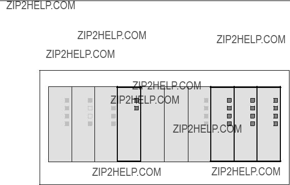
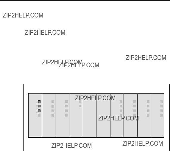
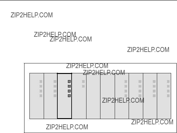
Possible Settings of the Ring Ports
Note
Only two ports of a switch can ever be defined as ring ports. All other ports in slots 6 and 7 that are not defined as ring ports can be used for the optical connection of nodes or subnets.
???Switch 1:
In the schematic below, switches R1 and R2 are set to OFF.
???Switch 2:
In the schematic below, switch R1 is set to ON and R2 is set to OFF.
???Switch 3:
In the schematic below, switch R1 is set to OFF and R2 is set to ON.
Figure

Installation and Commissioning
6.7.2SELECT / SET Button
The SELECT / SET button is used to switch over the display modes (DMode). After turning on the SCALANCE
The button has the following functions:
???Changing the display modes
By pressing the button briefly, you change from one display mode to the next. The selected mode or current status is displayed by the LEDs (DM1, DM2).
???Resetting to the factory defaults
It is possible to restore some of the factory default settings in DMode A by pressing the button for 12 seconds. You can cancel the reset procedure by re- leasing the button before the 12 seconds have elapsed. All previously made settings are overwritten by the factory defaults.
???Defining the fault mask and the LED displays
It is possible to set the fault mask in DMode A and DMode D. This allows you to specify the mask for signaling faults by defining an individual "good status??? for the connected ports and the power supplies. In this case, you press the button for 5 seconds in DMode A or DMode D. After 3 seconds, the two LEDs (DM1 and DM2) start to flash. You can cancel the procedure by releasing the button before the 5 seconds have elapsed. If, however, you press the button for a fur- ther 2 seconds, the current states of all ports and the states of the power sup- plies L1 and L2 are included in the fault mask. The previous fault mask is then overwritten.

Installation and Commissioning
6.8LED Display
Overview
The following table shows the states indicated by the LEDs in the various display modes. For more detailed information, refer to the subsections listed in the first col- umn.

Installation and Commissioning
6.8.1Startup Behavior of the SCALANCE
During device startup, the red LED on the power module signals the current status of the device. For more detailed information, refer to the following table:
Figure
Installation and Commissioning
6.8.2Selecting the Display Modes
Press the SELECT / SET button on the Switch CPU until the DM1 and DM2 light up on the CPU in the required combination. The selected display mode is then ac- tivated.
There is an automatic switchover to DMode A if the button is not pressed for longer than one minute.
Figure

Installation and Commissioning
6.8.3LED Display - Power Module
Display Modes A through C
In display modes A through C, the two LEDs DM1 and DM2 of the Switch CPU are lit as described in section 6.8.2. In these three states, the status of the signaling contact and the presence of the supply voltages are displayed by the LEDs of the power module.
Figure
The following table lists the significance of the three LEDs on the power module for display modes A through C:

Installation and Commissioning
Display in Display Mode D
In display mode D, both the DM1 and DM2 LEDs of the Switch CPU are on. This mode indicates whether the power supply is being monitored with the signaling contact.
Figure
The following table shows the meaning of the three light emitting diodes on the power module in display mode D:
Installation and Commissioning
6.8.4LED Display - DI Module
LED Display of the Digital Inputs 1 through 8
The status of four digital inputs (IN1 through IN4 or IN5 through IN8) can be indi- cated by the four LEDs on the front panel of the DI module.
Figure
Four modes (display mode A through D) are available and these are displayed by two LEDs (DM1, DM2) on the Switch CPU. The display modes A and C are identi- cal as are modes B and D.
Installation and Commissioning
6.8.5LED Display - Switch CPU
Display Modes A through D
The set display modes are indicated as follows:
Figure
The individual functions (RM, STBY and DM1 / DM2) are independent of each other. The LED displays are described below:

Installation and Commissioning
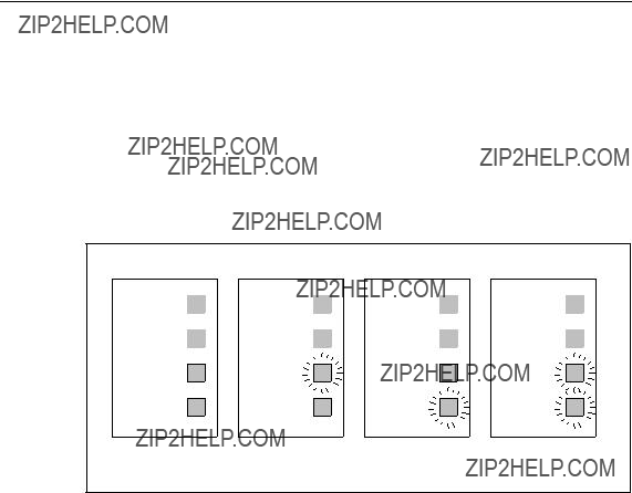
6.8.6LED Display of the Ports (DMode A through DMode D)
The two LEDs of slot 5 or the four LEDs of slots 9 through 11 of the basic device indicate various port statuses depending on the set display modes. The displays have the same significance for all ports on all slots of the basic device and the ex- tender modules
Port Statuses in DMode A
In display mode A, the current port status is displayed.
Figure

Installation and Commissioning
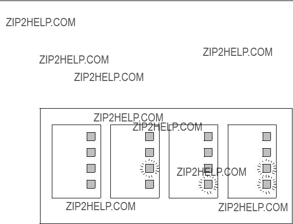
Port Statuses in DMode B
In display mode B, the current transmission rate is displayed.
Figure
Note
If there is a link fault and the type of transmission is fixed (autonegotiation off), in DMode B, the desired status, in other words the set transmission rate (1000 Mbps, 100 Mbps, 10 Mbps) continues to be displayed. If there is a link fault and autone- gotiation is active, the port LED goes off.
Installation and Commissioning
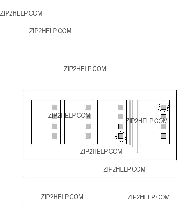
Port Statuses in DMode C
In display mode C, the current mode (half duplex, full duplex) is indicated.
Figure
Note
If there is a link fault and the type of transmission is fixed (autonegotiation off), in DMode C, the desired status, in other words the set type of transmission (full or half duplex) continues to be displayed. If there is a link fault and autonegotiation is active, the port LED goes off.

Installation and Commissioning
Port Statuses in DMode D
In display mode D, you can see whether or not the port is monitored.
Figure
Installation and Commissioning
6.9Replacing the
Removing the
It is only necessary to remove the
Notice
The
Inserting the
The
Figure

Installation and Commissioning
6.10Show Location
Determining the Location of a SCALANCE
To identify a SCALANCE
With the PST Tool V3.0, you can trigger this function with Module \ Ring.
For more detailed information, refer to the Configuration Manual
SCALANCE

Technical Specifications
Technical Specifications
MTBF information (mean time between failure)
Technical Specifications
344
Figure

Technical Specifications
7.2Media Module

Technical Specifications
7.3Media Module

Technical Specifications
7.4Media Module

Technical Specifications
7.5Media Module

Technical Specifications
Technical Specifications
Figure

Technical Specifications
Technical Specifications
Figure
Approvals, Certificates
Note
The specified approvals apply only when the corresponding mark is printed on the product. You can check which of the following approvals have been granted for your product by the markings on the type plate.
CE Marking
SIMATIC NET SCALANCE
???Directive 89/336/EEC "Electromagnetic Compatibility" (EMC Directive)
???Directive 73/23/EEC ???Electrical Equipment Designed for Use within Certain Voltage Limits??? (Low Voltage Equipment Directive)
???Directive 94/9/EEC Equipment and Protective Systems intended for Use in Po- tentially Explosive Atmospheres (Explosion Protection Directive).
The EU declarations of conformity are available for the responsible authorities ac- cording to the
Siemens Aktiengesellschaft
Automation and Drives
Industrial Communication SIMATIC NET
Postfach 4848

Approvals, Certificates
EMC Directive
The products are designed for use in an industrial environment:
Explosion Protection Directive
Complying with EN 50021 (Electrical apparatus for potentially explosive atmos- pheres; Type of protection ???n???)
II 3 G EEx nA II T3???T6
Note
When using (installing) SIMATIC NET products in hazardous area zone 2, make absolutely sure that the associated conditions are adhered to.
You will find these conditions on the SIMATIC NET Manual Collection CD.
Required FDA and IEC labels
The listed media modules meet the FDA and IEC requirements.
???
???
???
Complieswith21CFR
1040.10and1040.11 CLASS1LASERPRODUCT
Figure
FDA and IEC labels are not required for media module

Approvals, Certificates
Directive on Machines
The product remains a component in compliance with Article 4 (2) of the EU direc- tive on machines 89/392/EEC.
According to the directive on machines, we are obliged to point out that the product described is intended solely for installation in a machine.
Before the final product can be put into operation, it must be tested to ensure that it conforms with the directive 89/392/EEC.
Note for the Manufacturers of Machines
This product is not a machine in the sense of the EU directive on machines. There is therefore no declaration of conformity for the EU directive on machines 89/392/EEC.
If the product is part of the equipment of a machine, it must be included in the pro- cedure for obtaining the declaration of conformity by the manufacture of the ma- chine.
Installation Guidelines
The products meet the requirements if you adhere to the installation and safety in- structions contained in these Operating Instructions SIMATIC NET Industrial Ethernet SCALANCE
SIMATIC NET Industrial Twisted Pair and Fiber Optic Networks Manual /2/
This documentation is available on the Internet at
http://support.automation.siemens.com/WW/view/en/8763736
!Warning
Personal injury and damage to property may occur.
The installation of expansions that are not approved for SIMATIC NET products or their target systems may violate the requirements and regulations for safety and electromagnetic compatibility.
Only use expansions that are approved for the system.

Approvals, Certificates
Note for Australia
The product complies with the requirements of the AS/NZS 2064 standard (Class A)
UL Approval Information Technology Equipment
Underwriters Laboratories (UL) complying with Standard UL
Report number E115352
UL Approval Industrial Control Equipment
Underwriters Laboratories (UL) complying with Standard UL 508
Report number E85972
CSA Approval Information Technology Equipment
Canadian Standard Association CSA C22.2 No.
CSA Approval Industrial Control Equipment
Canadian Standard Association CSA C22.2 No.

Approvals, Certificates
cULus Approval Information Technology Equipment
cULus Listed 60E9 I. T. E.
Underwriters Laboratories Inc. complying with
???UL
???CSA C22.2 No.
cULus Approval Industrial Control Equipment
cULus Listed 69B1
Underwriters Laboratories Inc. complying with
???UL 508
???CSA C22.2 No.
cULus Approval Hazardous Location
cULus Listed 21BP I. T. E. FOR HAZ. LOC. Underwriters Laboratories Inc. complying with
???UL
???CSA C22.2 No.
???UL 1604 and 2279 (Hazardous Location) Approved for use in
Cl. 1, Div. 2, GP. A, B, C, D, T4 Cl. 1, Zone 2, GP. IIC T4
Cl. 1, Zone 2, Aex nC IIC T4
Note
When used in environments corresponding to Class I, Division 2 (see above), the product must be installed in a cabinet, a suitable enclosure, or closed room.

Approvals, Certificates
!Warning
In hazardous areas, personal injury or damage to property may occur if you make or break an electrical circuit while a SCALANCE
Do not connect or disconnect any live circuits unless risk of explosion can be exc- luded with certainty.
FM Approval
The product complies with the requirements of the standards
???Factory Mutual Approval Standard Class Number 3611
???FM Hazardous (Classified) Location Electrical Equipment: Non Incendive / Class I / Division 2 / Groups A,B,C,D / T4 and Non Incendive / Class I / Zone 2 / Group IIC / T4
ATEX Approval
The product complies with the requirements of the standard
??? EN50021
!Warning
Use under Zone 2 (or Div. 2)

Approvals, Certificates
Certification
The products and systems listed in this document are manufactured and marketed using a quality management system complying with DIN ISO 9001 and certified by DQS (certificate registration no. 2613). The DQS certificate is recognized in all IQNet countries (Reg. no. 2613).
Devices connected to the system must meet the relevant safety regulations.
The EU declaration of conformity is available for the responsible authorities according to the
Siemens Aktiengesellschaft
Automation and Drives
Industrial Communication SIMATIC NET
Postfach 4848
This declaration certifies compliance with the directives named above, but does not guarantee any specific properties.

Approvals, Certificates
Glossary

Glossary
Connection monitor- With regular link test pulses, SCALANCE
Glossary
Rapid spanning tree The Rapid Spanning Tree protocol (RSTP) allows redundant transmis- sion paths. This prevents circulating frames and, if a fault develops, provides an alternative path within one second (reconfiguration time).
Reconfiguration time The time required to restore a functional configuration if a device fails or a network cable is interrupted.

Glossary
Redundancy manager Switch in a ring topology that does not forward any frames between its (RM)ring ports if there are functioning connections between all other
switches. As soon as a connection between two switches is inter- rupted, the redundancy manager forwards frames between its ring ports and so restores an intact connection between all switches.

Glossary

Glossary
Index

Index

A&D Technical Support
Worldwide, available 24 hours a day:
Nuernberg
The languages of the SIMATIC Hotlines and the authorization hotline are generally German and English.

A&D Technical Support
Service & Support on the Internet
In addition to our documentation, we offer our
http://www.siemens.com/automation/service&support
where you will find the following:
???The newsletter, which constantly provides you with
???Exactly the right documents for your needs, which you can access by performing an online search in Service & Support.
???A forum in which users and experts worldwide exchange ideas and experiences.
???Information about local service, repair, and replacement parts. Much more information can be found under "Services".
You will find your local contact for Automation & Drives in our partners database at
http://www.automation.siemens.com/partner
A&D Technical Support