Siemens Applied Automation
Advance DataNET
Hub (DNH)
Siemens Applied Automation
Advance DataNET
Hub (DNH)

Copyright Notice
??? 2000 by Siemens Applied Automation Bartlesville, Oklahoma, 74003, U.S.A.
All rights reserved.
This publication is for information only. The contents are subject to change without notice and should not be construed as a commitment, representation, warranty, or guarantee of any method, product, or device by Siemens Applied Automation.
Reproduction or translation of any part of this publication beyond that permitted by Sections 107 and 109 of the United States Copyright Act without the written consent of the copyright owner is unlawful.
Inquiries regarding this manual should be addressed to: Siemens Applied Automation
Technical Communications 500 West Highway 60
Bartlesville, Oklahoma, 74003, U.S.A.

Table of Contents

Table of Contents, Continued

Preface
Audience & Purpose
Chapter Contents
This manual is intended to introduce users to the Advance DataNET Hub (DNH). It includes complete instructions for safe and proper installation of the DNH by installation personnel.
The manual provides the following information:
Technical Support
Getting Help
Before You Call
At Siemens Applied Automation we take pride in the on going support we provide our customers. When you purchase a product, you receive a de- tailed manual, which should answer your questions; however, our techni- cal support service provides a special ???hot??? line as an added source of information.
If you require assistance call:
Inside Oklahoma: (918)
Outside Oklahoma: (800)
Internationally:
Before you call one of our technical support lines. Please have the fol- lowing information available to help our representative answer your questions:
1.Unit Serial Number and Date of Installation
2.Description of problem
3.LEDs status on Communication Boards

Safety Practices and Precautions
Safety First
Terms in This Manual
Terms as Marked on Equipment
Symbols in This
Manual
Symbols Marked on Equipment
Grounding the
Product
This product has been designed and tested in accordance with IEC Pub- lication
WARNING statements identify conditions or practices that could result in personal injury or loss of life.
CAUTION statements identify conditions or practices that could result in damage to the equipment or other property.
DANGER indicates a personal injury hazard immediately accessible as one reads the markings.
CAUTION indicates a personal injury hazard not immediately accessible as one reads the markings, or a hazard to property, including the equip- ment itself.
This symbol indicates where applicable cautionary or other information is to be found.
DANGER - High voltage
Protective ground (earth) terminal
ATTENTION - Refer to Manual
A grounding conductor should be connected to the grounding terminal before any other connections are made.

Safety Practices and Precautions, Continued
Correct Operating
Voltage
DANGER Arising from Loss of Ground
Safe Equipment
Use the Proper Fuse
Safety Guidelines
Before switching on the power, check that the operating voltage listed on the equipment nameplate agrees with the available line voltage.
Any interruption of the grounding conductor inside or outside the equip- ment or loose connection of the grounding conductor can result in a dan- gerous unit. Intentional interruption of the grounding conductor is not permitted.
If it is determined that the equipment cannot be operated safely, it should be taken out of operation and secured against unintentional usage.
To avoid fire hazard, use only a fuse of the correct type, voltage rating and current rating as specified in the parts list for your product. Use of repaired fuses or
DO NOT open the equipment to perform any adjustments, measure- ments, maintenance, parts replacement or repairs until all power sup- plies have been disconnected.
Only a properly trained technician should work on any equipment with power still applied.
When opening covers or removing parts, exercise extreme care since "live parts or connections can be exposed".
Capacitors in the equipment can retain their charge even after the unit has been disconnected from all power supplies.
Dual Hub Modules
The dual hub modules (designated DataNET ???A??? Hub or DataNET ???B??? Hub) are connected via a serial
HUB ???A???
HUB ???B???
Overview, Continued
Package
Configurations
The Advance DataNET Hub (DNH) is available in three package configu- rations:
???
???Wall Mount Unit (Figure
???Zone 1 Wall Mount Unit (Figure
Advance Communi- cations System
Figure
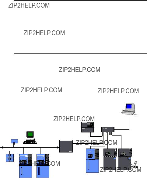
The Advance Communication System (ACS) is a
 APC 7.0
PCI
Overview, Continued
DataNET Hub
Hierarchy
Figure
Hierarchy
A network of DataNET hubs forms a
Ethernet Bridging
Figure
A hub can also connect
Figure
Bridging
DataNET hub

DataNET Hub Operation
DNH Links
Figure
Figure
The
Each connection between a DataNET Hub (DNH) and another device consists of two links. One link connects to the DNH ???A??? Hub, and one link connects to DNH ???B??? Hub. Both links can carry network traffic in normal operation. In the event that one link becomes unusable for any reason, the DNH will transparently and automatically
DNH and Maxum Com
Boards
An Advance Network Gateway or Maxum Analyzer that has an Advance Network Communication Board/DataNET (ANCB/DN) can connect to a DataNET hub via any of the eight

DataNET Hub Operation, Continued

DataNET Hub Specifications

DataNET Hub Specifications, Continued
nection
??? Fiber Optic Coupler for Fiber Optic Connections

DataNET Hub Specifications, Continued
DataNET Option, Standard
Cable
DataNET Option, Fiber Optic
Cable
???Cable connection by Belden 9182 (single pair) or Belden SSD1743 (two pairs) or equivalent; two pairs of wires are re- quired to support redundancy
???Two pairs of cable is required to support redundancy
???Shielded cable or unshielded cable in conduit is required for conformance to CE certified installation
???Two part connectors with
???Fiber optics connection by 62.5
???Two pairs of fibers are required to support redundancy
???Type ST mating connectors provided for field connection
???Approximately 3 mbps base transmission rate; uses dedicated transmission technique that does not require collision detection to achieve high data throughput efficiency

DataNET Hub Specifications, Continued
DataNET Cable
The following Table should be used when evaluating or selecting cable for an existing or new DataNET installation.
DataNET Hub Specifications, Continued
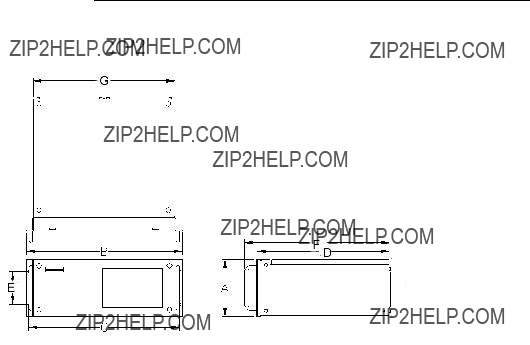
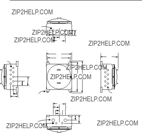
Figure
Dimensions

DataNET Hub Specifications, Continued
Figure
Dimensions
DataNET Hub Specifications, Continued
Figure
Mount
0
P
BOTTOM
S
TOP
Dimension Table
DataNET Hub Specifications, Continued
Figure


Unpacking and Inspection
Description
Receipt of DNH
Unpacking
Reporting Damage
This section provides the steps to follow when receiving and unpacking the Advance DataNET Hub (DNH).
When DNH is received, examine the shipping container for evidence of external damage. Outside damage may be an indicator of damage to the DNH. Record any external damage.
Open the carton containing the DNH and remove all packing material. Carefully remove the unit from the carton and inspect it for damage that may have occurred during transportation. Carefully examine shipped contents with those listed on the Bill of Lading. All items should match those on the Bill of Lading.
Perform the following inspections:
???Inspect DNH exterior for dents, chipped paint, scratches etc.
???Open DNH hinged top cover and visually inspect interior mounted assemblies, and connectors.
???If DNH is to be rack or wall mounted, be certain the proper mounting hardware is provided.
???Inspect all field wiring connectors and switches. There must not be any damage to these connectors or switches.
???Check internal power supply(s) for damage.
If there is any evidence of damage to the shipping carton or the DNH, notify the carrier and your local Siemens Applied Automation representa- tive. Keep all shipping materials as evidence of damage for carriers in- spection. Immediately contact your Siemens Applied Automation repre- sentative who will arrange for immediate repair or replacement. The Siemens Applied Automation Customer Service department can be con- tacted as follows:
Inside Oklahoma:
Outside Oklahoma:
Internationally:

Wall or Rack Mounting Installation
Instructions
Package
Configurations
Wall Mounting
The Advance DataNET Hub should be:
???Installed in a location that is free from shock and vibration.
???Protected from direct sunlight and extremes of temperature.
???It is recommended that the DNH be mounted within a shelter. This prevents DNH from being exposed to outside environmental condi- tions.
The unit is designed for standard wall or Zone 1 wall installations, or 19- inch rack installations; see Chapter 1. Figures
AC BREAKER
PROTECTION
POWER & DNH
CABLE OR WIRING
CONNECTIONS
The mounting wall must be capable of supporting the weight of the unit; see Chapter 1., Specifications and Figures
Wall Mount Installation: Use four,
Zone 1 Wall Mount Installation: Use four,

Wall or Rack Mounting Installation, Continued
Rack Mounting
CE Installations
Wiring Requirements
The DNH rack mount configuration is designed for a standard
For installation sites that must conform to CE (Conformite Europeene) Certification see page 23, CE Installations.
The wiring routing and entry requirements for the DNH are dependent upon the site requirements; see page 19, Site Wiring Requirements:
???CE (Conformite Europeene) Certified Area; see Page 23
???NEC Division 2 or
???Cenelec Zone 1 or Zone 2 Areas
???Rack Mounting

Site Wiring Requirements
Description
Wiring of Power to DataNET HUB
CE Installations
NEC Div 1, Div 2 or Non Rated Areas
Cenelec Zone 1 or Zone 2 Rated Areas
Non Rated Areas or Rack Mounting
How you wire to the DNH is dependent upon the site requirements:
???CE (Conformite Europeene) Certified Areas
???NEC Division 2 or
???Cenelec Zone 1 or Zone 2 Areas
???Rack Mounting
The installation should have a power disconnect external to HUB enclo- sure.
No voltage dependent selections need to be made on the HUB power supply, as it has a universal input.
See Page 23, CE Installations.
Use Metal Conduit wiring method.
Conductor type: Power cable sized for circuit protection chosen. Use Cable Gland wiring method:
Conductor type: Power cable sized for circuit protection chosen, and must be shielded.
Use Metal Conduit wiring method.
Conductor type: Power cable sized for circuit protection chosen.

Site Wiring Requirements, Continued
DataNET Channels
The DataNET channel connections can be either copper wire or fiber optic cable. The wiring method and cable type for DataNET is dependent upon the site requirements. For cable requirements see Table

Site Wiring Requirements, Continued
Copper Wire Site
Requirements
CE Installations
NEC Div 2 or Non- Hazardous Rated Areas
Cenelec Zone 1 or Zone 2 Rated Areas
DataNET Fiber Optic
Cable Connections
CE Installations
NEC Div 2 or Non-
Hazardous Areas
The following information pertains when using copper wire
See Page 23, CE Installations
Use approved Conduit wiring method. Conduit may contain multiple ca- bles. Adhere to all Federal and local electrical code requirements.
Cable Type: Refer to Table
Use Cable Gland wiring method. Each cable gland allows entry of one cable.
Cable Type: Recommend Belden 9182 or armored Belden 9182 or equivalent. The proper cable gland must be used to connect the armor or shield to the HUB enclosure. Other cables with individually shielded pairs can be used, but decreased distance is allowed (typically
Use approved flexible
Cable Type: Recommend Belden 9182 or equivalent. Other cables with individually shielded pairs can be used, but decreased distance is al- lowed (typically
The DataNET channel connections can be either copper wire or fiber optic cable. The wiring method and cable type for DataNET is dependent upon the site requirements. The following pertains when using copper wire.
See Page 23,CE Installations
Use approved Conduit wiring method. Conduit may contain multiple ca- bles. Adhere to all Federal and local electrical code requirements.
Cable Type: Duplex fiber, 62.5/125 micron; see Table
Connection: Type ST fiber connectors. Connect these to the appropriate transmitter and receiver ports for the respective channel.

Site Wiring Requirements, Continued
Cenelec Zone 1 or Zone 2 Rated Areas
Ethernet Communica- tion Links
CE Installations
NEC Div 2 or Non-
Hazardous Areas
Cenelec Zone 1 or Zone 2 Rated Areas
Use Cable Gland wiring method. Each cable gland allows entry of one duplex fiber cable.
Cable Type: Duplex fiber, 62.5/125 micron.
Connections: Type ST fiber connectors. Connect these to the appropri- ate transmitter and receiver ports for the respective channel.
Use approved flexible
Cable Type: Duplex fiber, 62.5/125 micron.
Connection: Type ST fiber connectors. Connect these to the appropriate transmitter and receiver ports for the respective channel.
The wiring method and cable type is dependent upon the site require- ments.
See Page 23,CE Installations
Use approved Metal Conduit wiring method. Conduit may contain multi- ple cables. Adhere to all Federal and local electrical code requirements.
Cable Type: Use
Connection: Connect to
Use Cable Gland wiring method:
Cable Type: Use shielded Category 5 cable and connectors.
Connection: Connect to
Use approved
Cable Type: Use unshielded Category 5 cable and connectors, see Ta- ble
Connection:
CE Installations
CE Installation Kit
Instructions
Available from Siemens Applied Automation CE Installation Kit P/N
The following information pertains to CE Installation of General Purpose, Zone 1 and Division 2 Equipment. For Zone 1 Installations, all cabling is terminated in the DNH Zone 1 Enclosure.

CE Installations, Continued
3.A split ferrite filter must be clamped to DataNET copper wire and fixed immediately to the outside of the DNH; use Siemens Applied Automation part number
4.Shielded Ethernet cable must be used for all Ethernet connections, in and outside the GC, and coupled through the enclosure using a shielded

Wiring Connections
ACCESS PLATES
Before You Begin
How you route the cable and wire to the DNH is dependent upon the site requirements. See Site Wiring Requirements (page 19) to determine the requirements for your site.
All wiring shall conform to the National Electrical Code (NEC) and/or other national or local code requirements.
Types of Connections

AC Power (Mains) Connections
DNH Power Supply
Each of the DNH electronic modules has a Power Supply Assembly lo- cated below the DataNET Hub board. Each power supply can accept inputs from
 AC INPUT CONNECTOR
Installation Note
Before You Begin
Depending upon the user configuration the power supplies can be con- nected in parallel and powered from a single power source or each sup- ply can be powered from two independent power sources. In either case disconnects must be provided for each input power source.
The DNH should be installed in a rack or wall mount; see Wall or Rack Mounting Installation; page 17. How you route the cable and wire to the DNH is dependent upon the site requirements. See Site Wiring Require- ments (page 19) to determine the requirements for your site.
All wiring shall conform to the National Electrical Code (NEC) and/or other national or local code requirements.
Instructions
1.Shut off the primary AC Power Supply lines to this location.
2.Open the door of the DNH by loosening the four captive screws located on each corner; use a 4mm Allen wrench.

AC Power (Mains) Connections, Continued

AC Power (Mains) Connections, Continued
7.Plug the connector back into its base and secure the two recessed captive screws.
8.If using redundant power supplies repeat steps 6 and 7. If not, use connecting wires to parallel connect to the other power supply.
9.Locate the DNH chassis ground lug  and connect wire from it to the building???s ground connection.
10.Inspect all connections for shorts or loose connections.
11.You are now ready to connect the DataNET channels; go to page 29.

DataNET Copper Connections
Description
A & B Hubs
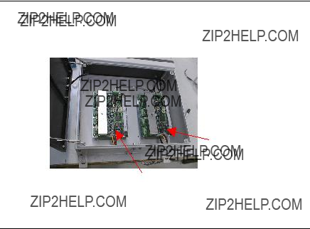
The DNH consist of two identical hubs in one enclosure. The left side is usually the DataNET ???A??? Hub and the right side is the DataNET ???B??? Hub. Each hub contains two DataNET Hub boards and power supplies. Figure
The DataNET ports can accept copper and/or fiber optic cables. In Data Hiway installations the DNH can use the existing Data Hiway cables.
Only the Ethernet port on the ???A??? Hub is active. The cable connection be- tween the two halves determines which is the ???A??? or ???B??? Hub half. See illustration below. A jumper wire visible across pin 1 and pin 2 on the ca- ble connector (J14) indicates that this side is the ???A??? Hub half.
Before You Begin
1.The wiring method (conduit or cable glands) and cable type you use for the installation is dependent upon the site requirements. Review the Site Wiring Requirements. Table
2.Make a block diagram of your existing or proposed network. The block diagram should show all devices and the placement of the DNH. If copper cable is being used, the diagram should show the es- timated cable lengths for each run. This information will be neces- sary in determining if any DataNET Hub Signal Equalizer Boards are required (see page 34).
3.Read through this section to familiarize yourself with port locations, terminal and jumper assignments, and wiring procedures. Refer to Figure
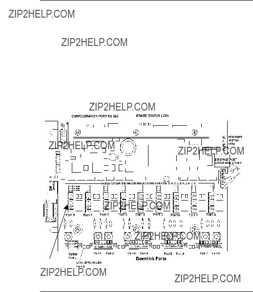
DataNET Copper Connections, Continued
DataNET Ports
See Figure
Note that each of the four Downlink Port connectors contains wiring con- nections for two DataNET port channels. The connector row (above the downlink port connectors) marked Port 9 and Port 1 through Port 8 pro- vides single port connector wiring for each of the eight channels. These ports are used for making Fiber Optic connections and/or when using a DataNET Hub Signal Equalizer Board.
Figure
PORT INTERFACE
CONNECTORS
Port Connections
To make wiring easier, all
Loosen the top wire retaining screws on the removed connector. Strip the insulation ??

DataNET Copper Connections, Continued
Cable Impedance
Settings
Behind each single port connector is an associated jumper pin block, see Figure
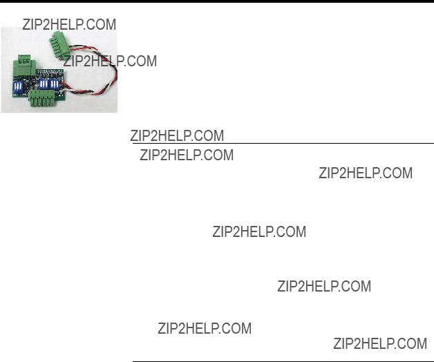
DataNET Hub Signal
Equalizer Board
Using Other than Recommended Cable
Recommended Cable
Downlink Port
Connections
+ Important
The Hub Signal Equalizer board balances the attenuation of signals when varying lengths of copper cable connect multiple downlinks from a HUB. The board plugs into a port connector and is wired to its associated downlink port. See DataNET Hub Signal Equalizer Board, page 34 for determining the attenuator board settings.
If you are using a cable other then the recommended cable types, the cable signals for each channel must be measured at the DNH port con- nection. These signal measurements are used to determine the attenu- ator settings for a DataNET Hub Signal Equalizer Board; see page 34.
Refer to Site Wiring Requirements. Table
All downlink connections are made to any of the
Always ensure that the same port number is used for redundant channel connections i.e. Channel A to Port 1 on ???A??? Hub and Channel B to Port 1 on ???B??? hub.

DataNET Copper Connections, Continued
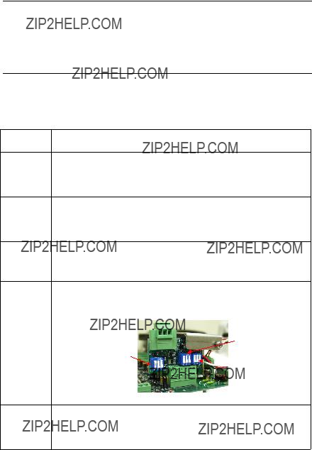
Down Link Wiring with DataNET Hub Signal Equalizer Board
1.Plug the DataNET Hub Signal Equalizer Board into the se- lected Port interface connector.
2.Connect the board???s pig tail leads to the corresponding hub downlink port channel; red lead to (+) terminal, black lead to
Master Port
Connectors
TB15 ??? TB18
3.Connect the downlink signal wires to the removable port connector (TB1) on top of the equalizer board. Positive to
(+) terminal; and Negative to
Board
Connector
.
4.If conduit is used the cable shield is only terminated at one end of the cable. If shield is terminated at this end connect it to terminal 3 (GND) on board. If using cable gland connec- tors, cable gland will always connect the shield to the chas- sis.
5.Set the switches on the board to the correct settings; see DataNET Hub Signal Equalizer Board Settings page 34.
DataNET Copper Connections, Continued
1.Connect the downlink signal wires to a hub downlink port. Positive to (+) terminal; and Negative to
Master Port
Connectors
TB15 ??? TB18
2.If conduit is used the cable shield is only terminated at one end of the cable. If shield is terminated at this end connect this shield to GND terminal. If using cable gland connectors, cable gland will always connect the shield to the chassis.
DataNET Hub Signal Equalizer Board
Description
Instructions
This section sets the switches on the DataNET Hub Signal Equalizer board. This board is used to equalize the signal amplitude when varying lengths of copper cable are connected to multiple downlink ports on the DNH.
Typically the smallest signal on any DNH port is found on the port with the longest copper cable. Since, Signal Equalizer boards are placed on ports with signal levels greater than 3 dB the port with the longest cable does not require a Signal Equalizer board.
This procedure determines the attenuator switch settings. When cable lengths are unknown, or the cable is other than the recommended cable (Table
Recommended Cable Refer to Site Wiring Requirements. Table
DataNET Hub Signal Equalizer Board, Continued
Switch Setting for Unknown Cable Lengths
Switch Settings for Known Cable Lengths
When cable lengths are unknown, or the cable is other than the recom- mended cable (Table
If the lengths of copper cable exceed those shown in Table
1.Measure and record the longest cable run (in Feet) con- nected from a device to any HUB port. The longest cable run does not require a Hub Signal Equalizer board.
2.Calculate the difference between the longest cable length and the length of cable connected to the port you wish to equalize.
3.Locate the difference in feet in the first column (Feet of Ca- ble) of Table
4.Identify the correct Selection range in column two of Table
Repeat the procedure for each connected port on the Hub 5. except the longest length that does not have an equalizer
board.

DataNET Hub Signal Equalizer Board, Continued
Sample Calculations
Calculation One:
Assume connections to Port 1 and Port 2 only.
Port 1 cable = 1000 ft. in length
Port 2 cable = 4000 ft. in length (3000 ft. difference)
Result:
Based on Table
Port 1 requires compensation for 3000 ft. Selection 4
Calculation Two:
Assume connections to Port 1, Port 2, and Port 6 Port 6 cable = 5000 feet
Port 1 cable = 1000 ft. (5000 ft. - 1000 ft. = 4000 ft. difference) Port 2 cable = 4000 ft. (5000 ft. - 4000 ft. = 1000 ft. difference)
Result:
Based on Table
Port 6 requires no compensation. Selection 1 (0 dB loss)
Port 1 requires compensation for 4000 ft. Selection 6 (3500 - 4500) Port 2 requires compensation for 1000 ft. Selection 2 (500 - 1500 ft.)
Note that the lengths of Port 1 and Port 2 cable are the same as in Cal- culation One, however, with the addition of a longer length for Port 6, new settings are required for Port 1 and Port 2.

Signal Equalizer Settings for Non Recommended Cable or Unknown Cable Lengths
Description
Before You Begin
Cable Requirements
Signal Measurements
This section is used to set the switches on the DataNET Signal Equalizer Board. If:
???the type copper cable used for port connections is other than the recommended cable
???the length of the cable runs are not known.
Read the section on the DataNET Hub Signal Equalizer Board (page 34) as a prerequisite to this section.
When cable lengths are unknown, or the cable is other than the recom- mended cable (Table
Signals are compared by measuring the levels at each of the copper ports and then adjusting the Equalizer board settings to within 3 dB of the weakest signal.
If cable lengths are significantly different or if signals differ by greater than ~4 dB, you may have to disconnect the cables on the short lengths to activate the longer cables in order to make a measurement.

Signal Equalizer Settings for Non Recommended Cable or Unknown Cable Lengths, Continued
View Measurements
Signals are viewed with an oscilloscope.
Scope characteristics: 10 MHz bandwidth capable of measurement sen- sitivity of 0.2 v/div to 1.0 V/div. A typical
Option 1.
Connection Point
Option 2. Connection
Point
Connect the two scope probes to the positive and negative terminals of the HUB Communications board, not the Equalizer board, of the channel to be measured. Alternatively, a connection can be made to the leads of the fuses for the selected channel.
???Set time base to ~1 or 2 millisecond per division.
???Observe two sequential signal envelopes of
The first signal envelope is the poll from the HUB to the slave device, and the second is the response back from the slave device. The reading from the poll should be ~5 volts
If a large amount of common mode line frequency interference is present the above choice may be unsuitable. In this case, Option 2. is recom- mended.
This option observes the signal across the termination resistor for the selected port.
Using this option, connect the two scope probes across an unused im- pedance jumper location. For instance, if the jumper is in the
Both channels should be
Using this method there is only one reading, the response message, which is seen. Responses may be from ~5 volts

Signal Equalizer Settings for Non Recommended Cable or Unknown Cable Lengths, Continued
Instructions &
Examples
This procedure is for determining the DataNET Signal Equalizer Board settings for other than the recommended cable or if the cable run lengths are unknown.

Signal Equalizer Settings for Non Recommended Cable or Unknown Cable Lengths, Continued
3.Examine the recorded signal levels and determine the dB loss for each port; refer to Table
Example:
With these signal levels, port 4 is the lowest level, so no at- tenuation is required. Its signal level becomes the reference for comparing the remaining ports??? signal levels.
The next strongest signal is on port 1. 1.6/1.25 = 1.28
20 log 1.28 = 2.1 dB or
ratio of 1.28
This is within the
The next strongest signal is on port 2. 1.75/1.25 = 1.4
20 log 1.4 = 2.9 dB or
ratio of 1.4
Since 2.9 dB meets the 3 dB variance allowed, selection 2 can be used (3.5 dB loss), which will put the level at about 0.6 dB below the signal on port 4.
Next is the signal on port 8. 4.5/1.25 = 3.6
20 log of 3.6 = 11.1 dB or
ratio of 3.6
Since this signal is 11.1 dB stronger than the signal on port 4, the attenuator board on port 8 needs to be set to selection 5 (11 dB loss). This should put its signal at about 0.1 dB above the signal of port 4.

Signal Equalizer Settings for Non Recommended Cable or Unknown Cable Lengths, Continued
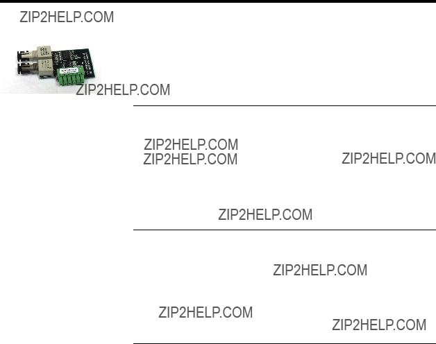
DataNET Fiber Optic Connections
DataNET Fiber Optic
Coupler
The Fiber Optic Coupler converts between electical signals and optical signals. The conversion is transparent to the network. Fiber Optic signals are impervious to distubances caused by electrical interference from nearby equipment, ground loops, power surges, or a nearby lightning strikes.
A DataNET Fiber Optics Coupler can drive up to 5000 feet of fiber optic cable.
Before You Begin
1.The wiring method (conduit or cable glands) and cable type you use for the installation is dependent upon the site requirements. Review the Site Wiring Requirements (page 19) to determine the require- ments for your site.
2.Refer to Figure
DataNET Fiber Optic Connections
Fiber Optic Cable
Type
Port Connections
Duplex Fiber, 62.5/125 micron
1.Plug the DataNET Fiber Optic Coupler board into the selected single Port board connector.
2.Connect the transmitter and receiver ports for the respective chan- nel.
TX TRANSMIT PORT
 RX RECEIVE PORT
PORT INTERFACE
CONNECTOR

Ethernet Connections
Description
ETHERNET PORT
Figure
The DNH consists of two identical hub modules in one enclosure. The left side is usually the DataNET ???A??? Hub and the right side the DataNET ???B??? Hub. Each hub contains a DataNET Hub board and power supply.
The DNH connects to the Ethernet local area network via the
HUB ???A???
HUB ???B??????
Active Ethernet Port
Only one Ethernet port is active in the DNH. The wiring connection be- tween the two halves determines which half has the active Ethernet port. A jumper wire visible across pin 1 and pin 2 on the cable connector indi- cates that the side to which it is connected is the active port, which we designate the ???A??? Hub. The hub that has the inactive Ethernet connection is the ???B??? hub.
Remember, only one Ethernet port can be active.

Ethernet Connections, Continued
1.The 10BASET data cable requires a minimum of two twisted pairs (transmit pair and a receive pair). The type wire used should conform to the AT&T
2.The maximum length of a 10BASET data cable can not exceed 328 feet (100 meters). Typically to increase the distance each DNH will connect to a hub or other type of repeater/medium converter.
3.The cable should be terminated at both ends with
Chapter 3
Data Communications Setup
Introduction
Overview
IMPORTANT
Command Line
Definitions
Important Checklist
This chapter provides maintenance personnel instructions for making the operational settings for the Advance DataNET Hub (DNH). Once these operational settings are made the DNH will function as a communication router on an Advance Communication System (ACS) network.
The DNH consists of two identical hubs (???A??? Half and ???B??? Half) in one en- closure. Each hub half contains a communication board and
Review Chapter 4, Command Line Summary. Chapter 4 provides defini- tions for all of the commands you will be using in this chapter.
Perform the following checklist before setting up the data communication protocol.
Inspect wiring of AC (mains)
Inspect all Uplink and Downlink port wiring connections.
Ensure that the Signal Equalizer Board settings are correct.
Ensure that each DataNET copper port has the correct im- pedance settings.
Inspect the wiring of the serial crosslink which determines which is the ???A??? Hub.
Ensure that when power is applied the Board Status LEDs are sequencing correctly.

Introduction, Continued
Chapter Preview
This chapter provides the following information:
Configuring Your PC
Description
Instructions
The Advance DataNET Hub (DNH) has a
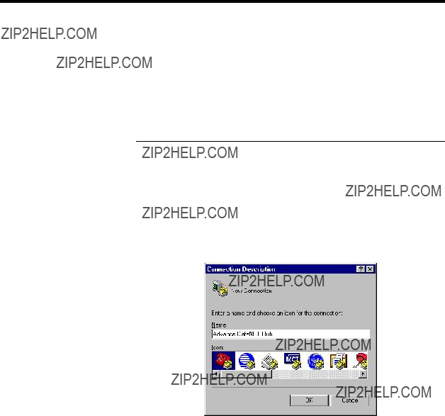
This procedure uses the Windows HyperTerminal program, to configure your PC to communicate with the DNH.
1.Click the Start button, and from the Program menu locate the
HyperTerminal Icon.
2.Click the HyperTerminal icon to start the Program. The Connection Description dialog box will open.
3.In the Name field, type in a Connection Name. Example: Advance DataNET Hub.
4.In the Icon field select an Icon to represent the name selected.

Setting Network Address, Continued

Configuring Your PC, Continued
8.Scroll each field and select the following Port Settings: Bits per second: 57600
Data Bits: 8
Parity: None
Stop bits: 1
Flow Control: None
9.Click OK.
The Main Menu will appear.
10.Click File and choose Properties from the
11.Click Settings tab.
12.From the Emulation scroll list select VT100. Do not change the de- fault settings for the other parameters.

Configuring Your PC, Continued
13.Click Terminal Settings button.
The Terminal Settings dialog box will appear.
14. Ensure that the following default settings are set:
Cursor:
??? Underline
???Blink:
Terminal Modes: none
Character set: ASCII
15.Click Ok
The Advance DataNET Properties box will appear.
Configuring Your PC, Continued
16.Click OK to return to main menu.
17.From the Main menu select File/Save As. The Save As dialog box will appear.
18. Enter the short cut name. Click Save to complete the setup.
Your PC is now setup to connect to and configure the DNH.
To create a shortcut to the new connection you just entered and place it on your Desktop, select the file name entered in step 21 and click the right mouse button. From the
Once the shortcut is created it can be moved to the Desktop. Simply click the shortcut icon and drag the icon while holding down the left mouse button. Release the mouse button to place the icon.

Establishing a Connection
HUB ???B???
HUB ???A???
Before You Begin
Password Protection
1.Ensure that the DNH Ethernet connection is not connected to the network by removing the
2.Connect a standard
3.Turn on the AC power to the DNH.
All utility programs on the DNH Communication board are password pro- tected. This insures the data integrity of all configuration data and limits unwanted access of the User???s network. To access any of the programs you must have a logon password.

Establishing a Connection, Continued
Password Format
A password name can consist of any combination of alphanumeric char- acters. The alphanumeric name must have a minimum of five and a maximum of twenty characters. The DNH Communication board is shipped from the factory with the word ???password??? entered as the de- fault password name.

Establishing a Connection, Continued
Remote Connection
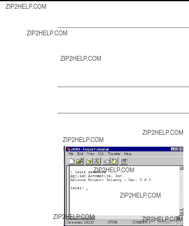
Log On
3.At the > prompt type: login password and press ??? Enter.
The Connect Screen will appear with the login information and the local prompt. The local prompt indicates that you are communicating with the DNH connected directly to the PC.
You are now ready to configure the DNH ???A??? hub or ???B??? hub with its own Network Address. go to page 57.
If your PC is connected to one of the DNH configuration ports you can connect to any other hub on the same network if you know the IP ad- dress of the DNH.
1.Open Windows HyperTerminal program on your PC.
2.Press ??? Enter twice, the Command Request dialog box will appear.
3.At the > prompt type: login password [IP Address].
Once the password is verified the system responds with the login infor- mation and displays the remote prompt which includes the IP address of the connected hub.
Setting Network Address
Description
Before You Begin
Command Line
Definitions
Instructions
This section provides instructions to configure an Advance DataNET ???A??? or ???B??? Hub with its own Network Address.
1.Connect a standard
2.Open Windows HyperTerminal program on your PC; reference Con- figuring Your PC, page 49.
3.Connect and Log on to DNH; reference Establishing a Connection, page 54.
Chapter 4, Command Line Summary, provides definitions for all of the commands you will be using in this chapter.
1.Log on locally to the DNH.
The Connect Screen will appear with the login information and the local prompt. The local prompt indicates that your are communicating with the DNH connected directly to the PC.

Setting Network Address, Continued
Assigning an IP Address
IP Address
How to Assign an IP Address
Table
Addresses
The IP Address consists of a
Ask your network administrator to assign you an IP Address, or if the DNH will be in a closed plant area and not connected to the Internet you can select an address from Table
192.165.0.11
192.165.0.12
192.165.0.13
192.165.0.14

Firmware Updates
5. From the Main Menu bar click on Transfer.

Firmware Updates, Continued
MAC Address Con- figuration
6.Click on Send Text File.
The Send Text File dialog box will appear. In the Look in: window choose the directory on your PC where the DNH files reside. Typi- cally this would be aai.
7.Under Files of type select All files (*.*).
8.Under File name type in the upgrade version file name (DataNET hub.hex).
This will start the down loading of the files. Once the download has begun the block numbers will be displayed as they are transmitted. The upload will take approximately 45 minutes to complete.
9.Repeat steps 1 through 8 for Hub ???B??? half.
To configure the Ethernet MAC address after the firmware upade per- form the following steps:
1. At the Local > prompt type: config address etherenet xx.xx.xx.xx.xx.xx
where: xx.xx.xx.xx.xx.xx is the MAX address for the DataNET Hub board. Typically the address would be in the range 00.c0.c9.01.21.00 through 00.c0.c9.01.21.ff.
2. Press ??? Enter to complete your entry.

System Status LEDs
Board Status LEDs
Startup LED Status
During the
After a normal
System Status LEDs,
Yellow (WARN) LED
Blink Codes
Continued
The yellow (WARN) blink codes are shown below. The yellow (WARN) status LED will light any time a link error is present. That is, any time at least one red (FAULT) link LED is lit, the yellow status LED will also be lit (green and red LEDs will be off).

System Status LEDs, Continued
Ethernet Port LEDs
Cross Link Status
LED
There are four Ethernet Link Status LEDs.
The cross link status LED is red when no link is established between the two DataNET Hub halves, and is green when a connection is detected. Usually a red indication is caused by the absence of the cross link cable or a faulty connection.

Troubleshooting
Configuration
Conflicts
Cabling errors:
Example
NOTE
The DNH port green LED is off, or intermittently flashes between green and red. This can indicate a configuration conflict caused by a faulty ca- ble or a wrong connection or improper configuration parameters.
1.Inspect all cable and connectors for damage.
2.Verify that the cable is connected to the correct Hub half and correct Port.
3.Verify that the Channel ???A??? link is connected to the ???A??? Hub half and that the Channel ???B??? link is connected to the ???B??? Hub half.
4.Verify that both Channels A & B use the same port number on their respective Hub half.
5.Display the Port Status screen by connecting a PC to the Configura- tion Port, logging in, and then typing display links. Verify that all Ports are connected as expected; see example below.
The following example shows that Port 1 on the B Hub is incorrectly con- nected to Port 1 Channel A, on device 172.16.99.7.
2Copper Unconnected
3Copper Unconnected
4Copper Unconnected
5Copper Unconnected
6Copper Unconnected
7Copper Unconnected
8Copper Unconnected
9Copper Unconnected
Ethernet Offline
The Ethernet port is always shown as Offline on the ???B??? Hub half because the Ethernet port is always disabled on the ???B??? Hub.

Troubleshooting, Continued
Make sure each Hub half has a unique IP address and that both Hub halves have the same device ID. Usually the device ID is set to the IP address of the ???A??? Hub.
Advance Network devices periodically broadcast their status for diagnos- tic and network routing purposes.
The Subnet mask must be identical on all Advance network devices (Maxum analyzer, NAU, ANCB, DNH), and connected to a single net- work, for the broadcast message to be received properly. If a remote de- vice does not show up in the device routing table, verify that the remote device matches the local device Subnet mask.

Troubleshooting, Continued
Signal Quality
Problems
Instructions
If a DNH port green LED is off, or intermittently flashes between green and red the signal levels for that port are either too high or low relative to the other Hub ports.
If a port link fails to connect at all, the port can be set to a test mode The test mode will cause port activity to occur approximately every 50 milli- seconds instead of approximately every 7 seconds as it would for an un- connected link. While in the test mode the signal for that port can be measured.
1.Connect a standard
2.Open HyperTerminal program on your PC; reference Configuring Your PC, page 49.
3.Connect and Log on to the DNH.
4.At the > prompt type: port stop num
Where num is a port number 1 through 9
5.Press ??? Enter.
6.At the > prompt type: test num
This places the selected port into a hardware diagnostic mode.
7.Using Option 1 or 2, (as outlined in ???Hub Signal Equalizer Board with Generic Cable??? section page 37) connect an oscilloscope to the port under test.
8.The signal received at the slave should be between ~0.75 v
9.If the signal is smaller than ~0.75 v
10.At the > prompt type: port start num
Where num is a port number 1 through 9.
11.Press ??? Enter.

Troubleshooting, Continued
12.At the > prompt type: test off
Test off places the selected port into a hardware diagnostic mode.
13.Disconnect test equipment and place unit into service

Chapter 4
Command Summary
Command Descriptions
Description
Unique Commands
This chapter is intended for maintenance personnel.
This chapter provides definitions for all of the commands you will be us- ing for setup purposes or for performing test diagnostics.
These are the commands that are unique to the Advance DataNET Hub.

Command Descriptions, Continued

Command Descriptions, Continued
???config address ip??? command
???config device id??? Command
This command configures the
config address ip 192.10.6.123
The IP address is automatically stored in the
Each pair of hub boards shares a common ???device ID.??? This ID must be configured into each board???s
One convenient convention for assigning device IDs is to use the IP ad- dress of the ???A??? half of each pair as the device ID.
???config display??? Command
???config netmask??? Command
This command displays the settings for the hub???s
This command sets the IP subnet mask for a
config netmask 255.255.192.0
The subnet mask is automatically stored in the

Command Descriptions, Continued
???config iproute??? Command
???config timeserver??? Command
???date??? Command
This command sets the address of the IP router to which the
config iproute 192.10.6.1
The router address is automatically stored in the
DataNET hubs may be configured to request time and date information from a DataNET time server. To do this, enter the
config timeserver 192.10.6.2
When a hub receives a reply to a time server request, it will update its local clock with the received time. Note that hub boards include their own
A hub???s time and date may also be manually configured (see date com- mand below).
Without an input argument, date displays the current date and time, as known by the
date yyyymmddhhmm
The argument part yyyy is the four digits of the year; the first mm is the month number; dd is the day number in the month; hh is the hour num- ber (24 hour system); the second mm is the minute number; and .ss (op- tional) specifies seconds.
For example, to set the date to Oct 8, 12:45 AM, type
date 199810080045
Command Descriptions, Continued
???del??? Command
???display??? Command
This command deletes selected items from the hub???s Source Address Table (SAT). The command offers options to delete all entries or se- lected entries by IP address or by MAC address. The command syntax is as follows:
del xx:xx:xx:xx:xx:xx or del xxx.xxx.xxx.xxx
where xx:xx:xx:xx:xx:xx is a MAC address in
Address xx:xx:xx:xx:xx:xx not found or Address xxx.xxx.xxx.xxx not found
If the deletion is successful, the
Address xx:xx:xx:xx:xx:xx deleted or Address xxx.xxx.xxx.xxx deleted
The entire SAT may be cleared with the command:
del all
Note that the SAT always contains one entry that may not be deleted, for the
Display the Source Address Table (SAT). This displays the MAC ad- dresses of all stations known to the

Command Descriptions, Continued
???display links??? Command
This command displays the
Example: local> display In this example, port 7 is running in diagnostic mode (see ???test??? com- linksmand) and port 1 is validating its link to device 8.8.8.8. Port 5 has been
taken offline, either with the ???port stop??? command, or because the hub detected a loop in the DataNET topology.
Example: local> display links 3
???download??? Command
If a hub port is connected to an Advance Network Gateway with Data- NET the display link command will also provide enhanced configuration information when the link number is specified
Use this command to load new firmware into the
1.Make sure you have a ???hub_rom.mot??? file available for download.
2.Log into the target Hub through the Configuration port, using Hyper- Term.
3.Type ???download??? at the hub???s prompt (???>???). The hub will then prompt to begin transmitting the download file.
4.Transmit the download file. Use the HyperTerm ???Transfer
Command Descriptions, Continued
???events??? Command
???dn??? Command
5.After you have selected the ???hub_rom.mot??? file and click on ???OK,??? HyperTerm will begin transmitting records to the Hub. The Hub will respond by periodically displaying addresses as the file downloads.
6.After approximately 5 minutes, the download will be complete. The hub will display messages indicating that the download has com- pleted, and it is erasing and programming the FLASH memory.
7.Finally, the Hub will reset, and display a new login prompt.
This command controls logging of hub software events. Software events mark the progress of the Hub software in some detail so board problems may be more easily analyzed. The events off command will stop the logging of event messages. The list command, as described above, is used to view the software events in the event buffer.
This command may be used to override default values for several pa- rameters related to the HDLC protocol used by DataNET. Specific forms of the command are:

Command Descriptions, Continued
dn window
dn window num
dn polldelay
dn polldelay time
dn portdelay
Displays the transmit ???window??? for the HDLC protocol used by DataNET. This is the number of
Sets the transmit window used by all ports on the hub. The parameter ???num??? must be a number 1 through 7. The de- fault window size is 7. The hub does not store the window size parameter in non- volatile memory, so
The ???poll delay??? parameter applies only to ports
Sets the poll delay to the value given, in milliseconds. Actual times are rounded down to the nearest ten milliseconds.
This parameter gives the delay, in milli- seconds, that a hub will enforce between message exchanges with a particular slave device. That is, before initiating a poll to a slave device, the hub will make sure that at least this much time has elapsed since the last poll to the same device. This keeps a hub from consum- ing all of the slave device???s processing time by continuously polling it at short intervals. This parameter defaults to 50 milliseconds.

Command Descriptions, Continued
dn portdelay time Sets the ???port delay??? parameter to the value given, in milliseconds. Actual times are rounded down to the nearest ten mil- liseconds.
The dn command is also used to enable and disable software tracing inside the hub software. This is intended to provide a software debug facility. The form for these commands is:
dn module on dn module off
In order to collect software trace events in the log buffer, you must also give the command ???events on.???
dn iframe on
The available modules are:

Command Description, Continued
???help??? Command
???list??? Command
This command generates a simple list of available commands.
Enter the list command at any time from the Configuration Management interface to see event buffer messages. The list command has an inter- nal current sequence number that is set to 1 each time a Configuration Management login occurs. The list command will show 21 messages each time it is entered, beginning with the current sequence number. The current sequence number is updated each time list is used. A new cur- rent sequence number can be entered with the list command:

Command Description, Continued
???login??? Command
The event display gives a
The user can view more than 21 messages by supplying a sequence number and list length:
The list length may appear by itself:
list ,32
This command lists the next 32 trace buffer entries, and increments the current message number by 32.
All the messages in the internal trace buffer can be viewed by listing se- quence number one then entering the list command until the last mes- sage is displayed. When the current message number is incremented to the last message in the internal buffer, it is automatically set to 1. You can list all the messages in the buffer without pausing between mes- sages with list 1,300.
There is a continuous listing mode for monitoring all the messages in the internal trace buffer. Start continuous list mode by entering list on. All the messages in the internal buffer will be displayed and any new mes- sages will be listed as soon as they are collected into the buffer. Termi- nate the continuous listing mode by entering a
To clear all events from the event buffer, use
list clear
This command logs the user onto the
Command Descriptions, Continued
???logout??? Command
???netstat??? Command
This command logs the user out of a session. The user must be logged out of the local device to login to a remote device.
This command may be used to display statistics for the DataNET sec- tion. If a link number is given, statistics are displayed for just that link. If no link number is given, summary statistics for all DataNET links are given. If the keyword ???clear??? is given, the statistics counters are reset to zero:
netstat dn [link] [clear]
Example:local> netstat dn clear
SCC 2: Subordinate Link 9. RUNNING
SCC 3: Principal (mux)Links 1 through 8. RUNNING
???port??? Command
This command will enable or disable normal DataNET communication on individual ports. Before placing a port into ???test??? mode (see test com- mand below), the port must first be taken offline with:
port stop num
where num is a port number, 1 through 9.
This command may also be used to reset a port that has been automati- cally taken out of service by the hub after detection of a DataNET topol- ogy loop:
port start num
This will

Command Descriptions, Continued
???test??? Command
???timeout??? Command
This command places a selected port into a hardware diagnostic mode. The command
test 4
places port 4 into test mode. The hub will generate poll messages on port 4. All other ports continue to operate normally. The command
test off
turns off test mode. Only one port at a time may be in test mode.
This command may be used to disable the user login timeout. Normally, if a user has not issued a CLI command for five minutes, the

Command Descriptions, Continued
???trace??? Command
The trace command controls the hub???s frame tracing function. This fea- ture captures network messages sent and received by the
Trace messages may be collected for the Ethernet port, the
Before issuing ???trace on,??? the user can set up trace filtering as described below. By default, tracing is set up for all frames on the Ethernet port.
To set up tracing, the trace command is followed by a list of ports and a filter mode. The port list is a
The port and filter options may be commanded separately or combined into a single command:
trace ethernet all
sets up tracing for all frames on the Ethernet link.
trace 2 input
Command Descriptions, Continued
???validation timeout??? Command
sets up tracing on downstream port 2, for input data only.
trace crosslink output
sets up tracing of frames sent on the
The filter may also specify frames for a specific station by declaring an IP address. The station filter cannot be combined with the port specifica- tion in a single command. To collect data from or to a station the com- mands would look like:
trace 9
trace 172.16.9.201
trace on
The first command specifies the upstream port for trace data. The sec- ond command filters the trace data to a single station???s frames, and the third command enables tracing.
Finally, the trace parameters may be reset to their default values (tracing all frames on the Ethernet port, without any address filtering) with:
trace reset
This command sets the time, in seconds, that the

Command Descriptions, Continued

Chapter 5
Parts Catalog
Introduction
Overview
How to Place an Order
This chapter is intended for maintenance personnel.
The Chapter provides a list of replaceable parts and assemblies for the Advance DataNET Hub (DNH). Subsequent information includes how to remove and replace the replacement part or assemblies.
Parts can be ordered from:
Siemens Applied Automation
Customer Service Order Entry 500 West Highway 60 Bartlesville, Oklahoma 74003 Inside Oklahoma:
Outside Oklahoma:
Internationally:
To ensure an immediate response to your request, you should provide the following:
???Purchase order number. If ordering by phone, a confirming P.O. should be sent.
???Address where the parts are to be shipped.
???Address where the invoice is to be sent.
???Siemens Applied Automation part numbers as listed.
???Quantity needed of each part.
???Equipment Serial number or project number of the system (espe- cially for warranty related orders).
???Preferred method of shipment.

Available Parts
Description
The available DNH assemblies and parts, with their applicable part num- ber are shown below.

Available Parts, Continued
Siemens Applied Automation
500 West Highway 60, Bartlesville, OK 74003
Phone