Type
Bidirectional Taxiway Light Fixtures
Document No. 96A0149
Issued: January 29, 1993
Rev. E: May 16, 2001
Manufactured to FAA Specification
AC
Copyright ?? 2001 by Siemens Airfield Solutions, Incorporated. All rights reserved.
Type
Bidirectional Taxiway Light Fixtures
Document No. 96A0149
Issued: January 29, 1993
Rev. E: May 16, 2001
Manufactured to FAA Specification
AC
Copyright ?? 2001 by Siemens Airfield Solutions, Incorporated. All rights reserved.
Record of Changes

Table of Contents

List of Figures
List of Tables

Warranties
Disclaimers
Products of Siemens Airfield Solutions manufacture are guaranteed against mechanical, electrical, and physical defects (excluding lamps) for a period of one year from the date of installation or a maximum of two years from the date of shipment and are guaranteed to be merchantable and fit for the ordinary purposes for which such products are made.
Siemens Airfield Solutions will correct by repair or replacement, at its option, equipment or parts which fail because of mechanical, electrical or physical defects, provided that the goods have been properly handled and stored prior to installation, properly installed and properly operated after installation, and provided further that Buyer gives Siemens Airfield Solutions written notice of such defects after delivery of the goods to Buyer.
Siemens Airfield Solutions reserves the right to examine goods upon which a claim is made. Said goods must be presented in the same condition as when the defect therein was discovered. Siemens Airfield Solutions furthers reserves the right to require the return of such goods to establish any claim.
Siemens Airfield Solutions???s obligation under this guarantee is limited to making repair or replacement within a reasonable time after receipt of such written notice and does not include any other costs such as the cost of removal of defective part, installation of repaired product, labor or consequential damages of any kind, the exclusive remedy being to require such new parts to be furnished.
Siemens Airfield Solutions???s liability under no circumstances will exceed the contract price of goods claimed to be defective. Any returns under this guarantee are to be on a transportation charges prepaid basis. For products not manufactured by, but sold by Siemens Airfield Solutions, warranty is limited to that extended by the original manufacturer.
This is Siemens Airfield Solutions???s sole guarantee and warranty with respect to the goods; there are no express warranties or warranties of fitness for any particular purpose or any implied warranties of fitness for any particular purpose or any implied warranties other than those made expressly herein. All such warranties being expressly disclaimed.
This manual could contain technical inaccuracies or typographical errors. Siemens Airfield Solutions reserves the right to revise this manual from time to time in the contents thereof without obligation of Siemens Airfield Solutions to notify any person of such revision or change.
Details and values given in this manual are average values and have been compiled with care. They are not binding, however, and Siemens Airfield Solutions disclaims any liability for damages or detriments suffered as a result of reliance on the information given herein or the use of products, processes or equipment to which this manual refers. No warranty is made that the use of the information or of the products, processes or equipment to which this manual refers will not infringe any third party???s patents or rights. The information given does not release the buyer from making their own experiments and tests.


Type
Runway Light Fixture
1. Safety
Safety Symbols
This section contains general safety instructions for using your Siemens Airfield Solutions equipment. Some safety instructions may not apply to the equipment in this manual. Task- and
To use this equipment safely,
???refer to the FAA Advisory Circular AC
???observe all safety regulations. To avoid injuries, always remove power prior to making any wire connections and touching any parts. Refer to FAA Advisory Circular AC
???read and become familiar with the general safety instructions provided in this section of the manual before installing, operating, maintaining, or repairing this equipment.
???read and carefully follow the instructions given throughout this manual for performing specific tasks and working with specific equipment.
???store this manual within easy reach of personnel installing, operating, maintaining, or repairing this equipment.
???follow all applicable safety procedures required by your company, industry standards, and government or other regulatory agencies.
???obtain and read Material Safety Data Sheets (MSDS) for all materials used.
Become familiar with the safety symbols presented in this section. These symbols will alert you to safety hazards and conditions that may result in personal injury, death, or property and equipment damage.
WARNING: Failure to observe this warning may result in personal injury, death, or equipment damage.
WARNING: Risk of electrical shock. Failure to observe this warning may result in personal injury, death, or equipment damage.

Safety Symbols (contd.)
Qualified Personnel
Intended Use
WARNING: Disconnect equipment from line voltage. Failure to observe this warning may result in personal injury, death, or equipment damage.
WARNING: Wear safety goggles. Failure to observe may result in serious injury.
CAUTION: Failure to observe may result in equipment damage.
The term qualified personnel is defined here as individuals who thoroughly understand the equipment and its safe operation, maintenance, and repair. Qualified personnel are physically capable of performing the required tasks, familiar with all relevant safety rules and regulations and have been trained to safely install, operate, maintain, and repair the equipment. It is the responsibility of the company operating this equipment to see that its personnel meet these requirements.
WARNING: Use of this equipment in ways other than described in this manual may result in personal injury, death, or property and equipment damage. Use this equipment only as described in this manual.
Siemens Airfield Solutions cannot be responsible for injuries or damages resulting from nonstandard, unintended applications of its equipment. This equipment is designed and intended only for the purpose described in this manual. Uses not described in this manual are considered unintended uses and may result in serious personal injury, death, or property damage. Unintended uses may result from taking the following actions:
???making changes to equipment that have not been recommended or described in this manual or using parts that are not genuine Siemens Airfield Solutions replacement parts
???failing to make sure that auxiliary equipment complies with approval agency requirements, local codes, and all applicable safety standards
???using materials or auxiliary equipment that are inappropriate or incompatible with your Siemens Airfield Solutions equipment
???allowing unqualified personnel to perform any task

Installation
Operation
Read the installation section of all system component manuals before installing your equipment. A thorough understanding of system components and their requirements will help you install the system safely and efficiently.
WARNING: Failure to follow these safety procedures can result in personal injury or death.
???Allow only qualified personnel to install Siemens Airfield Solutions and auxiliary equipment. Use only approved equipment. Using unapproved equipment in an approved system may void agency approvals.
???Make sure all equipment is rated and approved for the environment in which you are using it.
???Follow all instructions for installing components and accessories.
???Install all electrical connections to local code.
???Use only electrical wire of sufficient gauge and insulation to handle the rated current demand. All wiring must meet local codes.
???Route electrical wiring along a protected path. Make sure they will not be damaged by moving equipment.
???Protect components from damage, wear, and harsh environment conditions.
???Allow ample room for maintenance, panel accessibility, and cover removal.
???Protect equipment with safety devices as specified by applicable safety regulations.
???If safety devices must be removed for installation, install them immediately after the work is completed and check them for proper functioning.
Only qualified personnel, physically capable of operating the equipment and with no impairments in their judgment or reaction times, should operate this equipment.
Read all system component manuals before operating this equipment. A thorough understanding of system components and their operation will help you operate the system safely and efficiently.
Operation (contd.)
Action in the Event of a System or Component Malfunction
Maintenance and Repair
???Before starting this equipment, check all safety interlocks, fire- detection systems, and protective devices such as panels and covers. Make sure all devices are fully functional. Do not operate the system if these devices are not working properly. Do not deactivate or bypass automatic safety interlocks or
???Never operate equipment with a known malfunction.
???Do not attempt to operate or service electrical equipment if standing water is present.
???Use this equipment only in the environments for which it is rated. Do not operate this equipment in humid, flammable, or explosive environments unless it has been rated for safe operation in these environments.
???Never touch exposed electrical connections on equipment while the power is ON.
Do not operate a system that contains malfunctioning components. If a component malfunctions, turn the system OFF immediately.
???Disconnect and lock out electrical power.
???Allow only qualified personnel to make repairs. Repair or replace the malfunctioning component according to instructions provided in its manual.
Allow only qualified personnel to perform maintenance, troubleshooting, and repair tasks. Only persons who are properly trained and familiar with Siemens Airfield Solutions equipment are permitted to service this equipment.
???Always use safety devices when working on this equipment.
???Follow the recommended maintenance procedures in your equipment manuals.
???Do not service or adjust any equipment unless another person trained in first aid and CPR is present.
???Connect all disconnected equipment ground cables and wires after servicing equipment. Ground all conductive equipment.
???Use only approved Siemens Airfield Solutions replacement parts. Using unapproved parts or making unapproved modifications to equipment may void agency approvals and create safety hazards.

Maintenance and Repair
(contd.)
2. Description
???Check interlock systems periodically to ensure their effectiveness.
???Do not attempt to service electrical equipment if standing water is present. Use caution when servicing electrical equipment in a high- humidity environment.
???Use tools with insulated handles when working with electrical equipment.
This section describes the Siemens Airfield Solutions

manufactured in accordance with FAA specification AC

Figure 2. Optical Assembly

Optional Film Disc Cutout
Required Equipment
In case of lamp failure, an optional film disc cutout is available as an electrical bypass device. The film disc cutout closes an auxiliary circuit around the lamp within 15 seconds after lamp failure. This prevents all lights from going out when several lights are run from a single transformer. The film disc cutout must be replaced when the lamp is replaced.
CAUTION: Do not use a film disc cutout with voltage driven lights. Transformer may be damaged.
Refer to Table 2 for required equipment that is supplied. Refer to Table 3 for required equipment that is not supplied. Refer to the Parts section for part numbers.
Table 2. Required Equipment Supplied

Isolation Transformers
Refer to Table 4 for required isolation transformers.
Table 4. Required Isolation Transformers
Rated Lamp Life
2000 hours
Filter Colors
Green and yellow
Light Beam
Standard: 180 degrees bidirectional
Optional: switchable light direction

Mounting
The
Table 5. Connectors Supplied
Environmental Operating Conditions
The
Temperature
Altitude
Sea level to 10,000 feet (3050 m)
Relative Humidity
Up to 100 %
Dimensions
Weight
25 lb. (11.34 kg) (approximate)

3. Installation
Introduction
Unpacking
Input Requirement Summary
Installation Procedure
WARNING: Allow only qualified personnel to perform the following tasks. Observe and follow the safety instructions in this document and all other related documentation.
This section provides instructions for installing the
Each unit is individually packaged in a durable, cushioned, corrugated cardboard carton. To avoid unnecessary damage to the light assembly, unpack the carton at the installation site.
To unpack the carton, open the flaps and carefully remove the top packing material. Thread an eyebolt into each of the two opposite threaded holes. Run a rod through the eyebolts and lift the light assembly from the shipping carton. Set the light assembly in a protected area.
If damage to any equipment is noted, file a claim form with the carrier immediately. The carrier may request to inspect the equipment.
The
Installing the
Pavement Recess and Wireways Preparation
To prepare the pavement recess and wireways, follow the guidelines below.
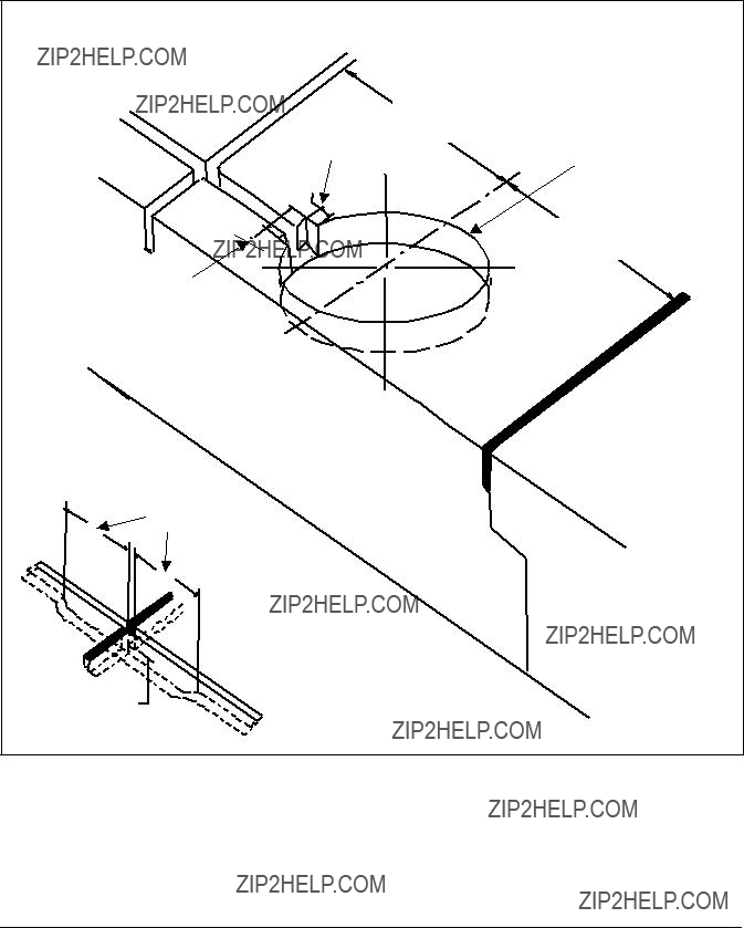
???See Figure 3. Drill the recess in the pavement. For the
Pavement Recess and Wireways Preparation (contd.)
Figure 3. Preparing Pavement Recess and Wireways

Pavement Recess and Wireways Preparation (contd.)
???Make sure the recess size and depth are maintained within specified limits.
???The recess side walls must be perpendicular to the pavement surface.
???The bottom surface must be flat or slightly concave to ensure that the base receptacle is resting securely and in true position.
???The recess can best be drilled using a
Wireways Preparation
To prepare wireways, follow the guidelines below.
???See Figure 3. The wireways should be sawed using a
???When the wireways cross construction joints, the sawcuts should extend
???Fill to 1 in. (25.4 mm) from the top of the pavement with an appropriate joint sealing filler in accordance with Item
Installation on
The light assembly is shipped complete, including the lamp, and is ready for installation.
To install the
1.Clean the base receptacle. Make sure that the base receptacle does not contain water and is completely clean and dry. The mating surfaces must be clean and free of foreign particles.
2.Slide a
3.Place the light assembly beside the opening in the
connection is solid and secure. Refer to Table 4 in Specifications in the Description section for required isolation transformers.

Installation on
(contd.)
Installation on Siemens Airfield Solutions Shallow Base
4.Turn on the power. Operate the light assembly for a minimum of five minutes. Turn off the power and allow the light assembly to cool.
5.Position the light assembly over the
Remove the eyebolts and lifting rod.
6.Turn on the power to check that the lamp will illuminate. Operate for a minimum of five minutes.
CAUTION: The light assembly will be hot after this test. Allow time for assembly to cool before proceeding.
7.Apply one drop of Loctite AV to each of the six light assembly mounting bolts. Install the six bolts and lockwashers. Torque the bolts to 185 ??5
To install the
1.Splice the light assembly leads to AWG 16 wires with suitable pre- insulated connectors, crimped with the proper tool.
2.Train the leads and AWG 16 wires carefully so they run along the bottom of the sawed wireways.
NOTE: Small wads of plastic insulating tape may be used to wedge the leads and cables in the bottom of the wireways if necessary. Refer to Table 4 for the appropriate isolation transformer required for installation between the fixture and the series lighting circuit.
3.Make sure the
4.Lightly sand blast and clean with solvent all external surfaces that will be bonded into the runway, except for the wire entrance seal. This is done to make sure an adequate bond between the shallow base and sealer exists.
CAUTION: Do not handle the light fixture by the leads. This can break the waterproof seal and cause electrical leakage.
Installation on Siemens Airfield Solutions Shallow Base (contd.)
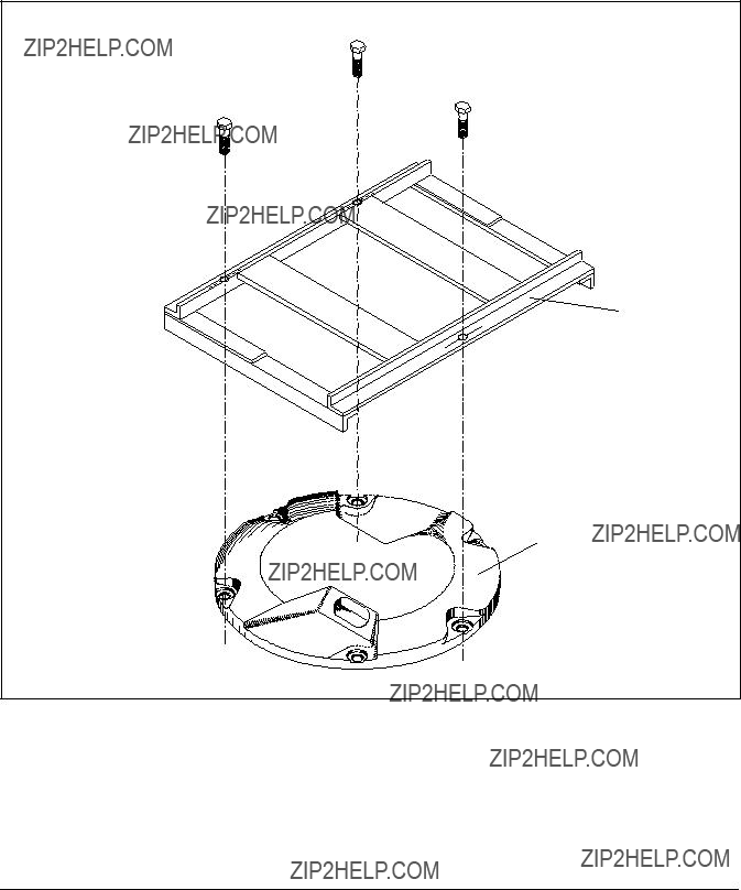
5.See Figure 4. Use an alignment jig to align the light assembly. The jig has three positioning screws that fit into the tapped holes holding the light fixture to the shallow base.
Bolt #2
Bolt #3
Bolt #1
1
2
Figure 4. Alignment Jig
1.Jig
2.

Installation on Siemens Airfield Solutions Shallow Base (contd.)
6.To attach the alignment jig, remove bolts #1, 2, and 3 from the light fixture.
7.Secure the jig with the three screws provided with the fixture. Contact the Siemens Airfield Solutions Sales Department if further information is required concerning the jig.
NOTE: It may be necessary to place temporary plugs for blocking the wireway entrance into the drilled holes or recess. The plugs will retain the sealer during the setting of the light assembly.
8.Cover the bottom of the shallow base completely with a
NOTE: When the base is placed in the recess, sealer material should be forced up the sides of the base at least 1/8 in. (3.175 mm).
NOTE: The jig is used to position the light assembly with arrows on the top of the fixture pointing along the taxiway centerline.
9.If necessary, place a weight on the jig to hold the light assembly in proper position.
10.Fill the remainder of the space between the sides of the base and the drilled recess with a liquid sealer to a level 3/4 in. (19 mm) below the pavement surface. The jig should be left in place until the sealer reaches its initial set.
11.If any voids are present around the shallow base after the initial set, they should be filled with
12.Fill the top 3/4 in. (19 mm) gap between the fixture and pavement with flexible sealing material to minimize water penetration and pavement deterioration.
13.Apply grade AV Loctite to the bolt threads, and reinstall the three bolts and lockwashers. Torque bolts to 185 ??5
14.Fill the wireways completely with a polyester compound and let it cure at least 24 hours before disturbing, unless otherwise specified. Refer to AC

4. Maintenance
Maintenance Schedule
This section provides maintenance information and procedures for the
Service life depends upon the entire assembly being waterproof. All surfaces must be clean, dry and free of all foreign matter and all bolts must be properly tightened if the light fixture is to operate for extended periods without requiring maintenance.
To keep the
Table 6.
???replacing lamp
???cleaning light channel and prism
???retorquing mounting bolts
???removing

Replacing Lamp
WARNING: Turn off the circuit before replacing lamp(s). Failure to observe this warning may result in personal injury, death, or equipment damage.
WARNING: Allow time for the unit to cool. High interior temperatures may cause severe burns to personnel. Failure to observe this warning may result in personal injury.
The preferred method of maintaining the
NOTE: It is recommended that you replace the lamp after 80% (1600 hours) of its useful life.
NOTE: If any lamps are out, record the location of the fixture and replace the lamp when the circuit is turned off.
Refer to Replacing Lamp in the Repair section for lamp replacement procedure.
Cleaning Light Channel and Prism
To clean the light channel and prism, perform the following procedure:
1.See Figure 5. Use a suitable fiber brush to remove all accumulated debris from the light channel (7).
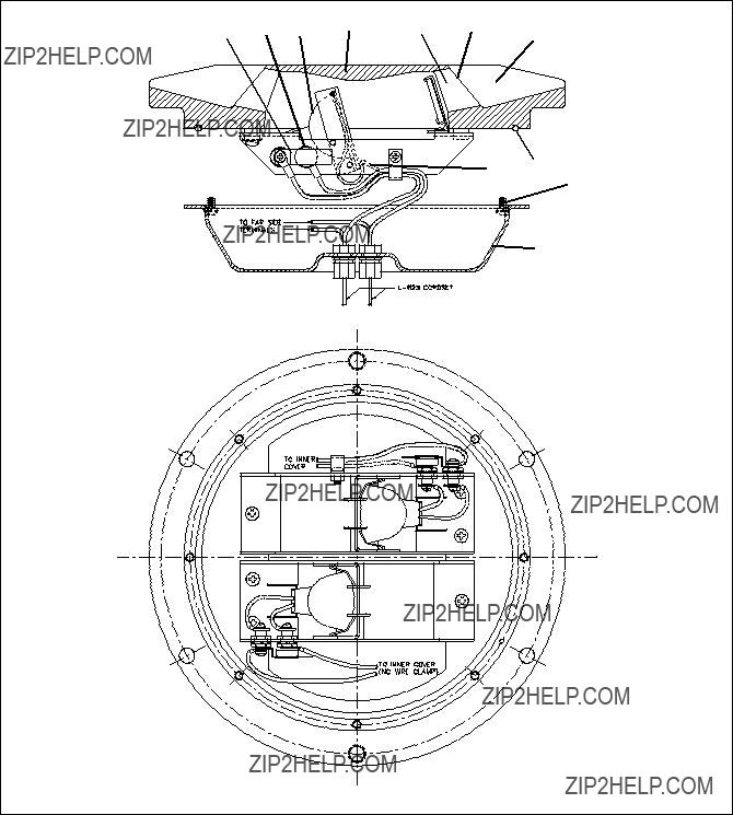
Figure 5. Cutaway View of Optical Assembly

Cleaning Light Channel and Prism (contd.)
2.Clean the outer surface of the prism (6) using liquid glass cleaner. If the prism is coated with a substance impervious to the cleaner, apply a suitable solvent sparingly with a wad of cotton or a patch of cloth. After the solvent has acted, remove the softened coating with a clean
piece of cotton or cloth. Dry the prism with gently, dry,
Retorquing Mounting Bolts
When retorquing mounting bolts, apply one drop of Grade AV Loctite to each of the six
See Figure 3. To torque the outer bolts across corners, tighten bolts in noted sequence: #1 and #4, then #2 and #5, then #3 and #6.
NOTE: Applying more than one drop of Loctite to the screw and bolt threads will create future difficulty in removal of the bolts.
NOTE: After several relampings, threaded holes may accumulate with dirt and excessive Loctite. If this occurs, screws may not seat properly. Clean holes with light weight oil or diesel fuel using a small fiber brush. Wipe the holes clean with alcohol to remove all oil or diesel fuel and dirt. Clean with dry,
Removing
Turn off the circuit when checking water level.
Check the water level in the
Water does enter the

this document and all other related documentation.
WARNING:
This section contains troubleshooting information. This information covers only the most common problems that you may encounter. If you cannot solve the problem with the information given here, contact your local Siemens Airfield Solutions representative for help.

6. Repair
Replacing Film Disc Cutout
Assembly
This section describes procedures for repairing and replacing parts.
It includes replacing the film disc cutout assembly, the lamp, and prism.
To replace the film disc cutout assembly, perform the following procedure:
1.Remove eight screws from bottom cover assembly.
2.Remove and inspect
3.Remove and replace cordsets and film disc cutout hardware as required using Figure 6 as a guide.

Figure 6. Replacing Film Disc Cutout Assembly
4.Install new or existing
5.Place bottom cover assembly in place and pull out majority of cordset slack.
NOTE: Leave enough cordset slack so that the pan can be opened.
6.Move bottom cover as required to check for lamp access for future lamp changes.
7.Permanently attach bottom cover with eight screws. Torque to 25 in- lb.

WARNING: Allow time for the unit to cool. High interior temperatures may cause severe burns to personnel. Failure to observe this warning may
To replace lamp, perform the following procedure:
1.Remove the six
2.Install two
3.See Figure 5. Turn the fixture upside down and remove the eight pan- head screws (9) holding the inner cover to the top cover assembly.
NOTE: The inner cover assembly (10) can now be separated from the top outer cover assembly (4). The inner cover assembly can now be moved from side to side to allow for lamp removal without having to adjust slack in the cordset.
4.Flip the holddown spring clip (11) off the lamp assembly (3), and pull the lamp assembly horizontally forward out of the socket.
CAUTION: The lamp assembly consists of a lamp and reflector. It is a single unit and is fragile. Handle with care. Failure to observe this warning could result in equipment damage.
5.Install the new lamp by reversing the lamp removal procedure.
CAUTION: Do not touch the quartz lamp inside the reflector with bare hands when handling the lamp assembly since this can reduce lamp life. If the lamp is touched, clean it with a lens cleaning tissue moistened with isopropyl alcohol.

7. Parts
Using the Illustrated Parts
List
To order parts, call Siemens Airfield Solutions Customer Service or your local representative. Use this
The Item column numbers correspond to the numbers that identify parts in illustrations following each parts list. NS (not shown) indicates that a listed part is not illustrated.
The Description column gives the part name, as well as its dimensions and other characteristics when appropriate. Indentions show relationships between assemblies, subassemblies, and parts.
The Part Number column gives the Siemens Airfield Solutions part number.
Numbering System
The Note column contains letters that refer to notes at the end of each parts list. Notes contain special ordering information.
Figure 7 shows how to determine the part number for a particular


List (contd.)
Figure 8.

Figure 8.
