SIMATIC
Program Port Expander
User Manual
Order Number: PPX:505??8131??1
Manual Assembly Number: 2806135??0001
Original Edition
SIMATIC
Program Port Expander
User Manual
Order Number: PPX:505??8131??1
Manual Assembly Number: 2806135??0001
Original Edition

! DANGER
DANGER indicates an imminently hazardous situation that, if not avoided, will result in death or serious injury.
DANGER is limited to the most extreme situations.
! WARNING
WARNING indicates a potentially hazardous situation that, if not avoided, could result in death or serious injury, and/or property damage.
! CAUTION
CAUTION indicates a potentially hazardous situation that, if not avoided, could result in minor or moderate injury, and/or damage to property.
CAUTION is also used for
Copyright 1996 by Siemens Energy & Automation, Inc.
All Rights Reserved ?? Printed in USA
Reproduction, transmission, or use of this document or contents is not permitted without express consent of
Siemens Energy & Automation, Inc. All rights, including rights created by patent grant or registration of a utility model or design, are reserved.
Since Siemens Energy & Automation, Inc., does not possess full access to data concerning all of the uses and applications of customer's products, we do not assume responsibility either for customer product design or for any infringements of patents or rights of others which may result from our assistance.

MANUAL PUBLICATION HISTORY
SIMATIC
Order Manual Number:
Refer to this history in all correspondence and/or discussion about this manual.

LIST OF EFFECTIVE PAGES

Contents
Chapter 1
Module Features . . . . . . . . . . . . . . . . . . . . . . . . . . . . . . . . . . . . . . . . . . . . . . . . . . . . . . . . . . . . . . . . . .
Chapter 2 Installing the Module
Contents iii

List of Figures
iv Contents

List of Tables
Contents v

Preface
This user manual provides installation and operation instructions for the SIMATIC???
This user manual is organized as follows:
???Chapter 1 provides a description of the module.
???Chapter 2 covers installation and checkout.
???Chapter 3 describes operation of the module.
???Chapter 4 discusses troubleshooting.

Chapter 1
Module Features . . . . . . . . . . . . . . . . . . . . . . . . . . . . . . . . . . . . . . . . . . . . . . . . . . . . . . . . . . . . . . . . . .
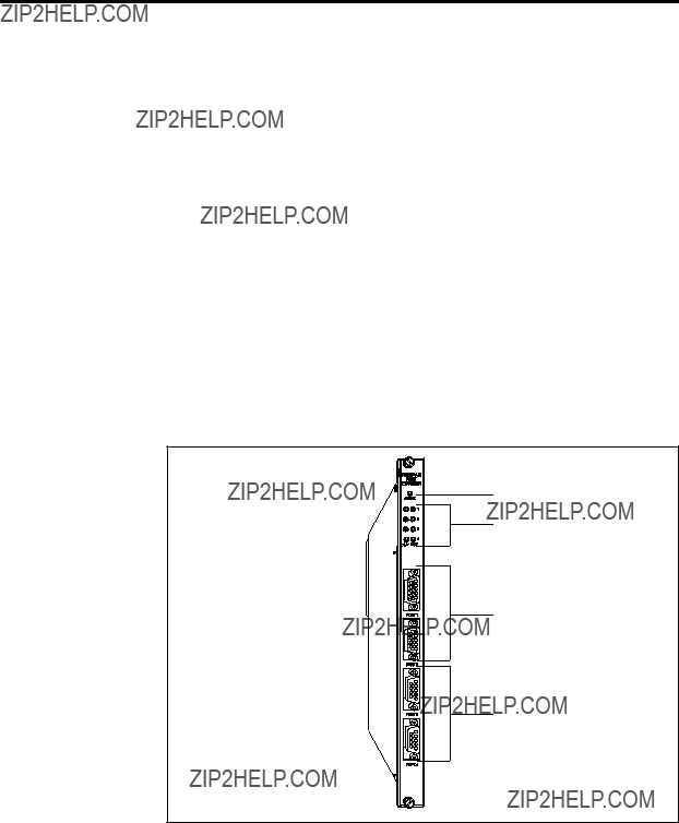
Module Features The
Ports 1 and 2 have an electrical interface that is a subset of RS??232C using a male DB9 connector. Ports 3 and 4 provide an RS??422 electrical interface using a female DB9 connector. Both interfaces have been chosen to match the programming ports provided on the SIMATIC 545 programmable controller. Thus, commonly used cables can be used with the
The ports may be configured to support baud rates of 1200, 2400, 9600, and 19,200. All four ports may be used simultaneously with a combined aggregate baud rate of 38,400 baud (for example, all four ports at 9600 baud). The
The red ??Active?? indicator is used to indicate module status. The indicator is illuminated when the module is functioning properly. See the troubleshooting section for additional details.
As control systems become more complex and dispersed, the demand for attaching serial devices has increased. Serial devices are typically used to provide operator interface, to run supervisory control and monitoring packages, and to facilitate controller programming support.
Most Series 505 controllers today are equipped with two serial ports to accommodate the minimum requirement. However, these ports can be consumed with the supervisory control package and one operator device. Some controllers, like the SIMATIC 525, provide only an
The
The simplest of these types of devices are COROS TD/OP operator panels. These operator interfaces provide for direct access to controller memory locations for read and/or write capability through an

More sophisticated applications may require the monitoring of a large number of variables in the controller. There are a number of third party applications available that may be used to access data from the controller and perform statistical process control, trending, report generation and other applications. These third party applications typically run on a PC or other platform but most all of them communicate to the controller directly through the program port. Often times there are multiple nodes that need to be connected to the controller. With the
Figure

Using a notebook PC running the SIMATIC TISOFT??? application, a maintenance engineer can easily make changes in the controller program or adjust timer and/or drum preset values. During start up conditions a PC may be attached to a serial port to aid in the debugging process. The additional ports on the
Figure
2.1Getting Started
The installation of the
! CAUTION
The components on the
To prevent this damage, the module is shipped in a special
After discharging any static build??up, remove the module from the
I/O base.

Table
On
Off
Not Used (Set to Off)
Hardware
Handshaking
Baud Rate
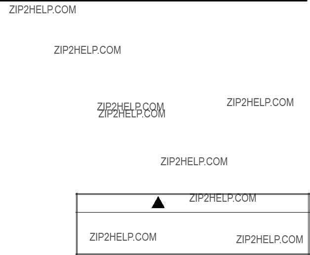
Example:
Dipswitch #1, #2 and #3 are shown in the ??OFF?? position for Port 1 indicating a baud rate of 9600 and hardware handshaking disabled.
Figure
Getting Started (continued)
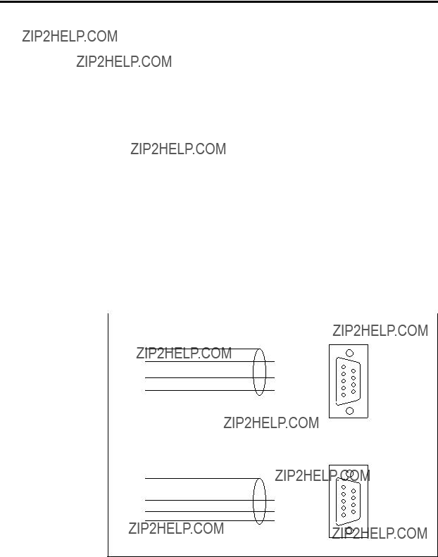
DB9
Figure

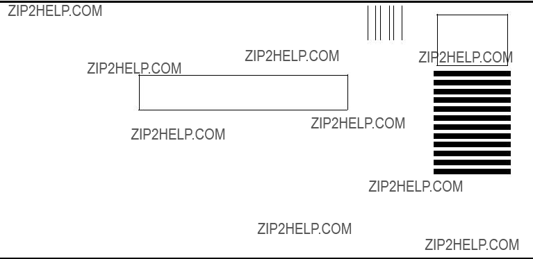
505 I/O MODULE DEFINITION FOR CHANNEL . 1 BASE . . . 00
Figure

Getting Started (continued)
In Figure
Use the attached operator interface device(s) to send commands to the controller and validate the resulting response. If you encounter a problem, refer to Chapter 4, Troubleshooting.

Chapter 3
Module Operation
The
NOTE: The ACTIVE indicator should remain on at all times after power up. Should the ACTIVE indicator go out or exhibit a blink pattern, refer to the troubleshooting section. When data is sent to a port the RCV indicator for that port should light briefly. Similarly, when data is sent from a port the XMT indicator should light briefly.
This release of the
Effect of Controller Because the
on scan time depends on several factors, including the type of request the controller is processing and the number of requests processed per scan. Some requests, such as a Read or Write memory location, can be processed relative quickly. Others, such as Find, consume significant controller CPU resources.
The SIMATIC 545 CPU can process a maximum of eight requests per scan. It is possible for the user, via Aux 16, to set the number of requests (task codes) that are processed each scan, for a minimum of one to a maximum of eight. A lower number should normally result in a faster controller scan time; the amount of increase depends on the type of request. However, since more requests can be processed each scan, this may improve data throughput through the

The requests are processed during the discrete portion of the controller scan (refer to Chapter 1 of the SIMATIC 545/555/575 System Manual for a discussion of the timeline). Thus, the scan interval to process the requests from the
To maximize throughput, the
Whether the effect on scan time is significant or not depends upon your application. If your controller is lightly loaded and/or task code requests routed through the


Table

Customer Response
We would like to know what you think about our user manuals so that we can serve you better. How would you rate the quality of our manuals?
Accuracy
Organization
Clarity
Completeness
Graphics
Examples
Overall design
Size
Index
Would you be interested in giving us more detailed comments about our manuals?
Yes! Please send me a questionnaire.
No. Thanks anyway.
Your Name:
Title:
Telephone Number: ( )
Company Name:
Company Address:
FOLD
NO POSTAGE
NECESSARY
IF MAILED
IN THE
UNITED STATES
BUSINESS REPLY MAIL
POSTAGE WILL BE PAID BY ADDRESSEE
ATTN: TECHNICAL COMMUNICATIONS M/S 519
SIEMENS ENERGY & AUTOMATION INC
P O BOX 1255
JOHNSON CITY TN 37605??1255
FOLD
????????????????????? ?????? ??? ??????????????????????????? ?????? ????????????????????? ???G???
?????????????????? ????????? ????????? ?????????OF??? ????????? ?????????????????????????????? ?????? ????????????????????? ????????? ?????????????????? ??? ??????????????????????????? ????????????
????????? ????????? ?????? ????????? ?????????????????????????????? ?????? ??????????????????????????????????????? ??? ?????????????????? ???????????????????????? ?????????????????????????????????