E n g l i s h
PN
E n g l i s h
PN
Data I/O has made a conscientious effort to ensure that the information in this document is accurate and complete. Data I/O assumes no liability for errors, or for any incidental, consequential, indirect, or special damages, including, without limitation, loss of use, loss or alteration of data, delays, or lost profits or savings, arising from the use of this document or the product which it accompanies.
No part of this document may be reproduced or transmitted in any form or by any means, electronic or mechanical, for any purpose, without written permission from Data I/O.
Data I/O is a registered trademark of Data I/O Corporation. TaskLink is a trademark of Data I/O Corporation.
Data I/O Corporation acknowledges the trademarks of other organizations for their respective products or services mentioned in this document.
SIPLACE is a registered trademark of the Siemens Corporation.
?? 2005 Data I/O Corporation All rights reserved

Chapter 1
Overview

The
1
Data I/O is proud to introduce a revolutionary new inline solution for
The
1.Takes programmable devices from a reel...
2.Places them in sockets and programs them with your data...
3.Places them on a conveyor belt...
4.Delivers them to the pick point of your assembly machine. ??

Jobs and Statistics
Programming Jobs
Statistics
TaskLink??? for Windows??? is required to process devices on the
TaskLink allows you to create and manage a job database and it analyzes job statistics.
PCMCIA cards are used to transfer jobs and statistics between TaskLink and RoadRunner.
For more information on TaskLink, see the TaskLink Help Menu. ??

External View
1.Power and Air Connections
2.Power Switch
3.Handhold for lifting
4.PCMCIA Card Slot and Eject button
5.Control Panel
6.Conveyor Belt with Dust Cover
7.Mechanical Interface to Assembly Machine
8.Robotics Cover
9.Communications Cable (optional)
10.Electronics Enclosure ??
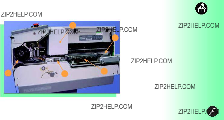
Internal Components

Control Panel Lights

Control Panel Buttons
2 1
3
4 5
1.Start - start or resume the chosen job.
2.Menu - exit to the previous menu,
3.Up and Down Arrows - move through menu items.
4.Select - select menu items.
5.Pause - interrupt the job without cancelling it. ??

Main Menu
Job
Advance Pocket
Align Pocket
Purge
Socket
???Light gray shaded fields cannot be changed.
???For Advance Pocket, Align Pocket, and Purge, see Chapter 3 in the Owner???s Manual.
Job
Prgrmr Yld: 99.6
Handler Yld: 99.5
Parts/Hour: 255
MCBI: 201
Skt 1 Yld: 99.9
Skt 2 Yld: 100
Skt 3 Yld: 100
Skt 4 Yld: 100
Skt Cycles: 249
End
Operator Menus
Socket
Socket 1: Enabled
Socket 2: Enabled
Socket 3: Enabled
Socket 4: Enabled
Adapter Statistics Reset Clean Clean Count Clean Alert: 3500 No: 22113204 Mfg: 09/23/02 Actuations:1055 Adptr. Life: 10000 Insertions: 4220 Pass: 4202
Fail: 16
Yld: 99.5
Socket 1 Insertions: 1055 Pass: 1053 Fail: 2
Yield: 99.8
Socket 2 [same as 1] Socket 3 [same as 1] Socket 4 [same as 1]
Operator Menus are visible on the RoadRunner control panel, and can
be navigated by using the Up Arrow and Down Arrow buttons.
Pressing the Menu button displays the menu that is one level up. If you are at the main menu, pressing menu will have no effect. Job is the first item in the main menu.
NOTE: To change languages
press Menu while pressing the
Select button. Arrow Down to
the desired language and press Menu twice.
Version 5.11.00 menus shown. ??
Supervisor Menus
Main Menu
Job
Advance Pocket
Align Pocket
Purge
Socket
Home
Operation
System
Robot Diagnostics
Programmer Diags
Event Log
???HOME sends the PNP Head to the Home position.
???Light gray shaded fields cannot be changed.
Job
End of List
Socket
Socket 1: Enabled
Socket 2: Enabled
Socket 3: Enabled
Socket 4: Enabled
Adapter Statistics
Reset Clean Count
Clean Count
Clean Alert: 3500
No: 22113204
Mfg: 09/23/02
Actuations:1055
Adptr. Life: 10000
Insertions: 4220
Pass: 4202
Fail: 16
Yld: 99.5
Socket 1
Insertions: 1055
Pass: 1053
Fail: 2
Yield: 99.8
Socket 2 [Same as 1]
Socket 3 [Same as 1]
Socket 4 [Same as 1]
View the Supervisor Menus by inserting a PCMCIA card with supervisor authority.
(The menus on this page and the next two pages are in addition to the Operator Menus.)
Supervisor (Administrator) authorization is set in TaskLink. For more information, refer to the TaskLink Help Menu.
Version 5.11.00 menus shown.
A (???) indicates the currently selected item.
A (X) indicates the current cursor position.

Supervisor Menus, continued
Robot Diags
Event Log
View
Clear
???Light gray shaded fields cannot be changed.
Refer to the previous page for the main menu.
NOTE: Programmer Diags are only available with a Diagnostic Adapter Board.

Supervisor Menus, continued
???Light gray shaded fields cannot be changed.
System
Status: Enabled
PGM: Fred???sRR2
IP: 139.138.16.215
Prog Port: 7596
SUB: 255.255.248
GTW: 139.138.16.1
SNS: 0.0.0.0
Refer to the main Supervisor Menu (2 pages back) for orientation.
1 Actuation duration is set by the Socket Adapter.
For more information about menu commands, see Chapter 3 of the


Chapter 2
Installation

Mounting on the Assembly Machine
1
2
To mount RoadRunner on an assembly machine:
1.With the feeder table pulled out, slide the supplied hook around a pin on the assembly machine feeder table.
2.Secure the hook to the table by tightening the thumbscrew.
NOTE: A black hook must be used on taller RoadRunners; a silver hook on older models. The label on the conveyor indicates which hook to use.
Warning:
Heavy; 16 kg (35 lbs). Do Not Drop.
Mount Only With Approved Hardware.

4
3
3.Slide RoadRunner under the hook so that its centering teeth engage the pin next to the hook.
4.Lower RoadRunner allowing the feeder table dowels to mate up with the bushings in the RoadRunner housing.
5.Verify that RoadRunner is secure before moving the feeder table back into the SMT machine. ??

Connecting Power and Air
2
1
To connect the power and the air:
1.Turn the RoadRunner power switch to the Off (0) position.
2.Grasp the air hose behind the ???quick connect??? collar and push it firmly onto the male fitting. The collar must be allowed to move back as it goes onto the fitting.
NOTE: Compressed air must be clean and dry at approximately 5.25 kgf/cm2(75 psi).
Warning:
Point Air Hoses Away From Body.
Wear Approved Eye Protection.


Connecting the Communications Cable
1
Red Dot
To connect the Communications Cable (option):
1.Correctly orient the connector (the red dot will be on top) and plug it into RoadRunner.
The socket is located on the back
2.Similarly orient and plug the other end of the cable into the SMT feeder table. Use the socket that corresponds with the track that RoadRunner is mounted on.
To unplug the cable, pull back on the connector collar. ??

Running the
1
Data I/O Corporation
Version: 02.00.00.B
To run the
1.Turn the power switch On (I).
All the control panel indicator lights will come on. When the
If all the indicator lights start blinking, a serious error has occurred. Turn the unit off then on again. If the error continues, have the unit serviced.
2.If no errors display, RoadRunner is operation ready. ??

Chapter 3
Job Setup

Inserting a Job Card
1
Data I/O Corporation
Version 02.00.00.B
To run a job, insert a TaskLink job card in the PCMCIA card slot. Use only TYPE I or TYPE II PCMCIA cards.
To insert a job card:
1.If the power switch is on, make sure the blue lamp is lit.
Caution:
Electrostatic Discharge May Cause Damage.
Discharge Static Against Common Ground
Prior to Inserting Job Card.


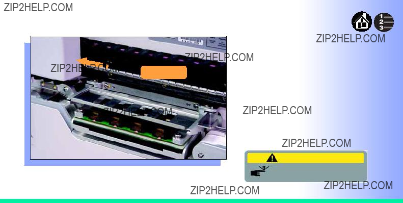
Changing the Precisor
Warning:
Pinch Warning. Keep Hands
Away From Moving Parts.

4. When inserting the new precisor, make sure that the part number faces up and that the small holes near the precisor edge fit over the dowel pins on the PNP head.
There should be no visible gap between the precisor and the head. ??
4
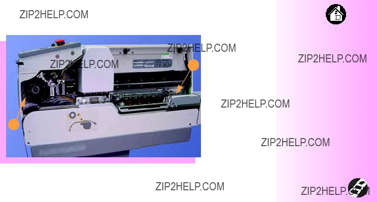
Changing the Actuator Plate
 PNP Head
To change the Actuator Plate:
1.Select Job, then End, wait for the blue lamp to light and turn the power Off (0).
2.Lift off the Robotics Cover.
Once power is off, the PNP Head can be moved by hand to allow access to the Actuator Plate.
Warning:
Pinch Warning. Keep Hands
Away From Moving Parts.
3.Pull the Actuator Plate to slide it out of the grooved brackets.
NOTE: The Actuator Plate must be out to access or change the Socket Adapter.
To change the Socket Adapter, see the procedure on the following page. ??
3

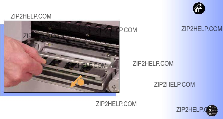
Changing the Socket Adapter
3. Without touching the gold contact surfaces on the bottom of the adapter, lift the adapter free.
4. Insert the correct adapter, making sure that it seats on the dowel pins.
NOTE: Each type of device may have its own Socket Adapter.
5. Tighten the screws and replace the Actuator Plate. ??
3

Adjusting the
Current
Setting
2
If you have an Adjustable
Adjustable
1.With the power off (0), move the PNP Head out of the way.
2.Loosen the Position Locking Screw using a 4 mm Allen wrench.

6
6

Loading a Reel of Devices
To load a reel of devices:
1.Make sure the reel is correctly installed in the rack of the assembly machine.
NOTE: A reel axle is required.
2.Insert the tape into the
3.Select Advance Pocket from
the Operator Menu, then press the Up Arrow button.
4.When the tape is advanced past the peel bar, separate the cover tape from the device tape.

5
5
5.Thread the cover tape up through the cover tape path and attach it to the Cover Tape
NOTE: A small piece of adhesive tape may be needed to stick the cover tape to the
6.Turn the
Align the tape pockets as described in the following procedure. ??


Chapter 4
Operation

Running a Job
> Job
Advance Pocket
Align Pocket
Purge
3
1
To run a job:
1.Insert a job card in the PCMCIA card slot.
2.Clear the conveyor belt of any unneeded devices.
3.Press Start.
The green lamp will start blinking.
When the programmed devices reach the assembly machine pick point, the belt will pause and the green lamp will stay lit without blinking. ??

Pausing or Stopping a Job
> Job
Advance Pocket
Align Pocket
1
> Job
Advance Pocket
Align Pocket
To pause at the end of the current
2operation:
1.Press Pause on the control panel.
To instantly stop in an emergency situation:
2.Press the Emergency Stop button. ??
Warning
Electrical shock hazard. The

Ending a Job
1
Whenever you are going to change job cards, you must first end the current job.
To end the current job:
1.Press Pause button.
2.Choose End from the Job Menu. Job is in the main menu.
The system will finish processing devices and place the devices on the belt, but no additional devices will get picked from the tape.
3
3.Clear away excess devices from the conveyor belt.
4.Empty the Reject Bin. (See next heading.)
5.Empty the Cover Tape

Emptying the Reject Bin
2
To empty the Reject Bin:
1.Press the Pause button.
2.Pull the Reject Bin out by grabbing the finger tab and then lift up and out.
When reinserting the Reject Bin, be sure the bin is completely lowered so that the tab is positioned out of the path of the probes. ??
Warning:
Pinch Warning. Keep Hands
Away From Moving Parts.

Emptying Cover Tape
4
To empty the Cover Tape
1.Press Pause.
2.Cut the cover tape, leaving enough slack to reattach.
3.Pull the
4.Unwind the used cover tape and discard it.
5.Replace the
Warning:
Pinch Warning. Keep Hands
Away From Moving Parts.

Shutting Down
> Job
Advance Pocket3
Align Pocket
1
To shut down RoadRunner:
1.Press Pause.
2.Select End Job from the Job Menu and wait for all devices to be placed on the belt.
3.Turn the power Off (0).
4.Remove devices from the conveyor belt.

Restarting a Job
4
5
To restart RoadRunner after a pause or an emergency stop:
1.Turn the Emergency Stop button clockwise to release it, if needed.
2.Press Menu until the main level menu is displayed
3.Select Align Pocket.
4.Press the Up Arrow to advance the device tape until the next pocket center hole lines up with the alignment mark.
5.Press Start.
The job will resume. ??

Chapter 5
Maintenance

Cleaning with Air
1
2
To prevent dust accumulation, inject compressed air into the following component areas:
1.
2.Sockets (daily). Sockets should be opened and closed by hand while air is injected.
NOTE: Compressed air must be clean and dry. ??
Warning:
Point Air Hoses Away From Body.
Wear Approved Eye Protection.

Cleaning with Alcohol
2
1
To prevent dust and oil accumulations, clean the following component areas with isopropyl alcohol on a
1.Chassis and Covers (every 3 months).
2.Conveyor belt (daily). See "Device Rotation" in the Troubleshooting chapter.
NOTE: Dry the conveyor belt before rotating it.
These intervals are based on running 40,000 devices weekly. ??

Running the
1
Run the
To run the
1.Press Pause.
2.Clear all devices from the sockets and from the conveyor belt.
3.Toggle the power switch off and then back on.
The
4.Check the display for system errors. ??
Chapter 6
Troubleshooting

Viewing Errors
To view and correct errors:
> U8 RevA ID27
Devices: 800
Rejected: 0
Parts/Hr: 567
3
1.Messages will appear in the keypad display.
2.Check the
If you cannot correct the error condition, contact a service technician.
3.Press Menu to remove the message.
If there are other error messages the next one will appear.

Stop
Caution
Motor Controller not responding
Some common error messages are listed below. For more information see ???Troubleshooting??? in the
Manual.
1Twist the Emergency Stop button to release it. ??

Enabling a Socket
If a socket repeatedly becomes disabled, RoadRunner should be serviced.
To
1.Choose Socket from the top level menu.
2.Arrow down and select the disabled socket from the Socket menu. (A dot appears.)
3.Press the Up Arrow button to
NOTE: To disable a probe, disable the probe???s corresponding socket. ??

Clearing Jammed Tape
3
If the tape jams, an error message displays and the blue lamp illuminates.
To clear the tape path:
1.Press the Emergency Stop
button (to continue the job later) or select Job, then End, and turn the power off.
2.Unroll one turn of cover tape and cut it near the
3.Pull the tape out backwards until the cover tape end is free.
4.Cut the device tape.
5.Pull the tape out where it exits to remove it from the machine.
6.Trim away any flaws before reloading. ??

Device Rotation
3 Clean
3 Dry
3 Rotate & Repeat
If devices rotate excessively on the conveyor belt:
1.Press Pause. Wait for all the devices to get picked from the belt.
2.Press the Emergency Stop.
3.Remove the Dust Cover and clean only the exposed surface of the conveyor belt with isopropyl alcohol on a
4.To continue, replace the
Conveyor Dust Cover, release the Emergency Stop button and press Start. ??

Technical Support
Contact your local Data I/O representative.
To find your local representative, go to http://www.dataio.com/contact/repsearch.asp
Worldwide
Data I/O Corporation
Shipping address:
10525 Willows Road N.E.
Redmond, WA USA 98052
Mailing address:
P.O. Box 97046
Redmond, WA USA
You can also find answers by visiting our Knowledge Base on our Web site at www.dataio.com, then click
Support, then Knowledge Base Search.

www.dataio.com