Instruction Manual  July 2009
multiranger 
100/200
Instruction Manual July 2009
multiranger
100/200

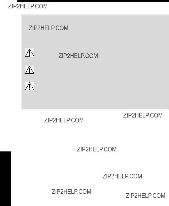
Safety Guidelines: Warning notices must be observed to ensure personal safety as well as that of others, and to protect the product and the connected equipment. These warning notices are accompanied by a clarification of the level of caution to be observed.
Qualified Personnel: This device/system may only be set up and operated in conjunction with this manual. Qualified personnel are only authorized to install and operate this equipment in accordance with established safety practices and standards.
Unit Repair and Excluded Liability:
???The user is responsible for all changes and repairs made to the device by the user or the user???s agent.
???All new components are to be provided by Siemens Milltronics Process Instruments Inc.
???Restrict repair to faulty components only.
???Do not reuse faulty components.
Warning: Cardboard shipping package provides limited humidity and moisture protection. This product can only function properly and safely if it is correctly transported, stored, installed, set up, operated, and maintained.
This product is intended for use in industrial areas. Operation of this equipment in a residential area may cause interference to several frequency based communications.
Note: Always use product in accordance with specifications.
MILLTRONICS??is a registered trademark of Siemens Milltronics Process Instruments Inc.
???For a selection of Siemens Milltronics level measurement manuals, go to:
www.siemens.com/processautomation. Under Process Instrumentation, select Level Measurement and then go to the manual archive listed under the product family.
???For a selection of Siemens Milltronics weighing manuals, go to:
www.siemens.com/processautomation. Under Weighing Technology, select Continuous Weighing Systems and then go to the manual archive listed under the product family.
?? Siemens Milltronics Process Instruments Inc. 2009

Contents of Table

Table of Contents
ii

Contents of Table
iii

Table of Contents
iv

Contents of Table

Table of Contents

Contents of Table
vii

Table of Contents
viii
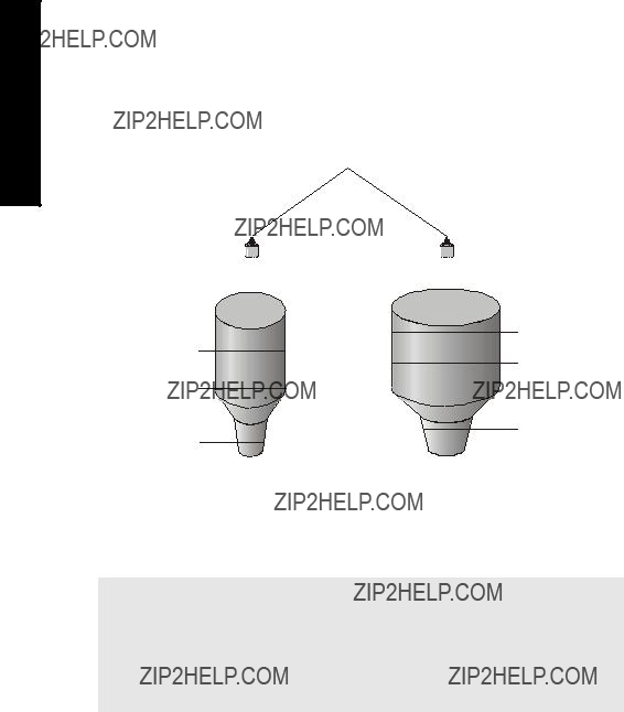
The MultiRanger 100 and 200
The MultiRanger is available in two models, MultiRanger 100 and MultiRanger 200, and is designed for a variety of applications:
???water and wastewater
???storage tanks, for measuring liquids, slurries, and solids
???hoppers, ore bunkers, flotation cells
MultiRanger 100
The MultiRanger 100 is a single or
MultiRanger 200
The MultiRanger 200 is a single or
The Manual
Notes:
???This product is intended for use in industrial areas. Operation of this equipment in a residential area may cause interference to several frequency based communications.
???Please follow the installation and operating procedures for a quick,
The manual provides instruction for both MultiRanger 100 and MultiRanger 200 models. For your convenience, the manual uses MultiRanger 100 features as its standard content. Additional MultiRanger 200 features are clearly marked.
The manual is designed to help you get the most out of your MultiRanger, and it provides information on the following:
1.Modbus is a registered trademark of Schneider Electric.
100/200 MultiRanger
MultiRanger 100/200
If you have any questions, comments, or suggestions about the manual contents, please email us at techpubs.smpi@siemens.com.
For the complete library of Siemens Milltronics manuals, go to
www.siemens.com/processautomation.
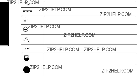
Manual Symbols
Please note their use carefully.
Alternating Current
Direct Current
Earth (ground) Terminal
Protective Conductor Terminal
Caution (refer to instructions)
No
Configuration Examples
The configuration examples used in this manual illustrate the versatility of the MultiRanger. Because there is often a range of ways to approach an application, other configurations may also apply.
In all examples, substitute your own application details. If the examples do not apply to your application, check the applicable parameter reference for the available options.
Should you require more information, please contact your Siemens Milltronics representative. For a complete list of Siemens Milltronics representatives, go to www.siemens.com/processautomation.

Specifications
Power
AC version
???
???fuse: F3: 2 AG, Slow Blow, 0.375A, 250V
DC version
???
???fuse: F3: 2 AG, Slow Blow, 2A, 250V
Transmitter fuse
??? F1: Belling Lee, L754, 4000A HRC, ceramic type, 100mA, 250V
Temperature Sensor fuse
??? F2: Belling Lee, L754, 4000A HRC, ceramic type, 50mA, 250V
Mounting
Location
??? indoor / outdoor
Altitude
??? 2000 m max.
Ambient temperature
???
Relative humidity
???Wall Mount: suitable for outdoors (Type 4X / Nema 4X, IP65 Enclosure)
???Panel Mount: suitable for outdoors (Type 3 / Nema 3, IP54 Enclosure)
Installation category
??? II
Pollution degree
??? 4
1. Power consumption is listed at maximum.
Specifications

Specifications
Range
??? 0.3 m (1 ft) to 15 m (50 ft), dependent on transducer
Accuracy
??? 0.25% of maximum range or 6 mm (0.24???), whichever is greater
Resolution
??? 0.1% of program range1 or 2 mm (0.08???), whichever is greater
Memory
???1 MB static RAM with battery backup
???512 kB flash EPROM
Programming
Primary
??? handheld programmer
Secondary
???PC running SIMATIC PDM
???PC running Dolphin Plus software
Display
??? back lit LCD
Temperature Compensation
??? Range:
Source
???integral transducer sensor
???
???programmable fixed temperature
Temperature Error
Sensor
??? 0.09 % of range
1.Program range is defined as the empty distance from the face of the transducer (P006) plus any range extension (P801).

Fixed
??? 0.17 % per ??C deviation from programmed value
Outputs
Transducer drive
??? 315 V peak
mA Analog
MultiRanger 100/200:
Single or Dual point versions include two mA outputs
???
???
???750 ohm maximum
???Resolution of 0.1%
???Isolated
Relays1
???One:
???1 control
???Three:
???2 control
???1 alarm control
???Six:
???4 control
???2 alarm control
???All relays rated 5A at 250 V AC,
Control Relays
??? 1, 2 or 4 Form A, NO relays (numbers 1, 2, 4, 5)
Alarm Relay
??? 0, 1 or 2 Form C, NO, or NC relay (numbers 3, 6)
Communication
???
???
Optional
??? SmartLinx?? compatible
1.All relays are certified only for use with equipment that fails in a state at or under the rated maximums of the relays.
Specifications

Specifications
Inputs
mA (analog) (1) [MR 200 only]
???
Discrete (2)
???
???logical 0 = < 0.5 V DC
???logical 1 = 10 to 50 V DC
???3 mA maximum draw
Enclosure
Wall Mount
???240 mm (9.5") x 175 mm (6.9"). Width dimension includes hinges.
???Type 4X / NEMA 4X / IP 651
???Polycarbonate
Panel Mount
???278 mm (10.93") x 198 mm (7.8") Width dimension includes flange.
???Type 3 / Nema 3 / IP54
???Polycarbonate
Weight
???Wall mount: 1.37 kg (3.02 lb)
???Panel mount: 1.5 kg (3.3 lb)
Approvals
??? See product nameplate
Compatible Transducers
??? Echomax series and STH series
Transducer Frequency
??? 44 kHz
1.For watertight applications, use only approved, suitable size hubs in the enclosure???s conduit holes.

Cable
???Do not use coaxial cable for transducer (see General Appendix F: Upgrading on page 246 for more information)
???transducer and mA output signal to be 2 copper conductors, twisted with shield/drain wire, 300 Vrms, 0.324 - 0.823 mm2 (22 - 18 AWG), nominal capacitance between
adjacent conductors @ 1kHz = 62.3 pF/m (19 pF/ft). Nominal capacitance between conductor and shield @ 1kHz = 108.3 pF/m (33 pF/ft) (Belden??1 8760 is acceptable)
???365 m maximum
Note: The MultiRanger is to be used only in the manner outlined in this instruction manual or protection provided by the equipment may be impaired.
Specifications
1. Belden is a registered trademark of Belden Wire & Cable Company.
Installation
Notes:
???Installation must only be performed by qualified personnel, and in accordance with local governing regulations.
???This product is susceptible to electrostatic shock. Follow proper grounding procedures.
All field wiring must have insulation suitable for at least 250 V.
Hazardous voltage present on transducer terminals during operation.
DC terminals shall be supplied from an SELV source in accordance with IEC
???The
Mounting
Mounting Locations
Recommended
Avoid
???Exposure to direct sunlight. (Provide a sun shield to avoid direct sunlight.)
???Proximity to high voltage/current runs, contacts, SCR or variable frequency motor speed controllers

Mounting Instructions
The wall mount and panel mount units install differently. Please follow the specific instructions for your unit.
Note: When routing cable through a conduit, please follow the Cable Routing instructions on page 10 before mounting the MultiRanger.
Wall Mount
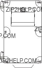
Enclosure Dimensions
lid screws
(6)
240 mm
(9.45") 227 mm
(8.93")
Mounting the Enclosure
1. Remove the lid screws and open the lid to reveal the mounting screw holes. 2. Mark and drill four holes in the mounting
surface for the four screws (customer supplied).
3.Fasten with a long screwdriver.
Please note:
??? Recommended mounting: directly to wall or to electrical cabinet back panel
???Recommended mounting screws: #6
???If alternate mounting surface is used, it MUST be able to support four times the weight of the unit.
Installation
Cable routed through a conduit:
1.Remove the four mounting screws holding the motherboard to the enclosure.
2.Be careful not to damage the electronics with static electricity. Remove the motherboard from the enclosure by pulling the board straight out.
3.Drill the required cable entry holes. Make sure conduit holes do not interfere with the lower areas on the terminal block, circuit board, or SmartLinx card.
4.Attach the conduit to the enclosure using only approved suitable size hubs for watertight application.
5.Reinstall the motherboard with the mounting screws.
suitable location for conduit entrances
.
Panel Mount
Installing the panel mount unit requires making a cutout in the panel. The dimensions for the cutout are provided in the illustration below. A full size cutout template is provided with your unit or may be downloaded from www.siemens.com/processautomation.
Cutout Dimensions
Installation
Cutout Instructions
1.Select a place for the unit and fasten the template onto the panel (use tape or tacks).
2.Drill the four fastener holes.
3.Make the cutout using the appropriate tools.
4.Mount unit according to the instructions in this manual.

Panel Mount Dimensions
36 mm (1.40")
278 mm (10.93")
Mounting the Enclosure
Helpful hint:
???Use tape to hold hexagonal heads in slots while attaching wingnuts.
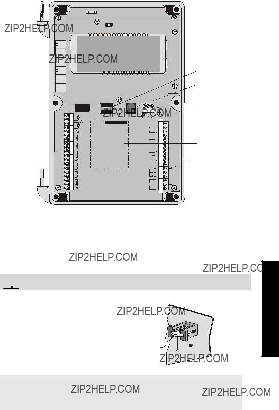
MultiRanger Board
Installing the Battery
The battery (Rayovac BR2032) has a


 Disconnect power before replacing the battery.
Installation Steps
1. Open the enclosure lid.
2.Slide the battery into the holder. Be sure to
align the + and ??? terminals correctly. 3. Close and secure enclosure lid.
Battery
+
Note: All parameter values are written to the EEPROM once every hour. The battery is used to backup Standard Data Logging parameters
Installation

Installing SmartLinx Card
SmartLinx cards are generally
1.Align card with the two mounting posts and then
2.Use the screws supplied with the card to attach it to the mounting posts.
3.Wire in the SmartLinx card according to SmartLinx Manual.
Installation
Wiring
Please note:
???Verify that all system components are installed in accordance with instructions.
???Connect all cable shields to the MultiRanger Shield Terminals. Avoid differential ground potentials by not connecting cable shields to ground (earth) anywhere.
???Keep exposed conductors on shielded cables as short as possible to reduce noise on the line caused by stray transmissions and noise pickup.
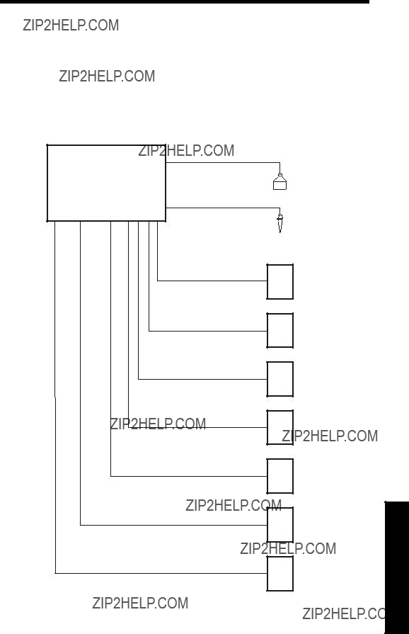
Siemens Milltronics
Sensor
Laptop running
Dolphin Plus
Customer Alarm,
Pump, or Control
Device
Customer Device, digital output
Customer Device, analog output
Customer Network or
Modem
SmartLinx Card
Display, PLC, Chart recorder, or other Control Device
Wiring
Wiring
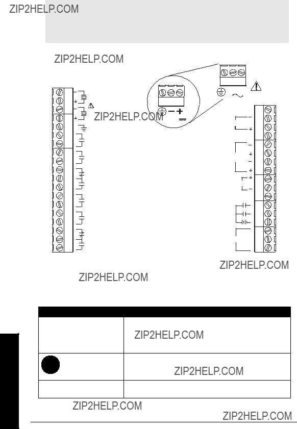
Terminal Board
The terminal board on the MultiRanger allows all inputs and outputs to be connected simultaneously.
Note: Recommended torque on terminal clamping screws.
???0.56 - 0.79 Nm
???5 - 7 in.lbs
Please do not overtighten the screws.
Cables
The MultiRanger transceiver requires a shielded
Transducers
Warning: Hazardous voltage present on transducer terminals during operation.
Run the transducer cable in a grounded metal conduit, separate from other wiring (except
Notes:
???Do not use coaxial cable because of electrical noise interference
???Do not connect the shield and white transducer wires together; wire to separate terminals
???Disregard older transducer manuals that recommend these practices
white
TRANSDUCER TWO
black
white
TRANSDUCER ONE
black
A 0.1 ??F (100V or greater) capacitor is included with the MultiRanger for retrofitting old MultiRanger Plus installations. Please see MultiRanger 100/200 Installation (for retrofitting MultiRanger Plus Installations) on page 247.
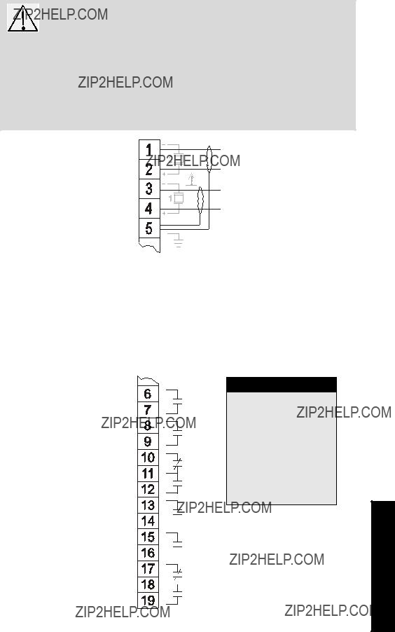
Relays
Relay contacts are shown in the
Relay Ratings
 RELAY 4
 RELAY 5
 RELAY 6
Power Failure
Relays 1, 2, 4, and 5 are normally open and will fail in the normal state.
Relays 3 and 6 can be wired either normally open or normally closed, and will fail in their de- energized states.
Wiring

Temperature Sensor
Accurate temperature readings are critical to accurate level measurements because the speed of sound changes, depending on air temperature, and all Siemens Milltronics Echomax and
If the following conditions apply, a separate
???the transducer is exposed to direct sunlight (or other radiant heat source)
???the transducer face and monitored surface temperature differs
???faster response to temperature changes is required
TEMPERATURE SENSOR
Note
Use a
mA Input [MR 200 only]
For more information, consult the Transducer (P004) and mA Input Parameters (P250, P251, and P252) in the parameter reference section.
mA Output
For more information, consult the mA output parameters (P200 to P219) in the parameter reference section.
Wiring

Level System Synchronization
Note: The MultiRanger 100/200 CANNOT be synchronized with the MultiRanger Plus or the HydroRanger.
When using multiple ultrasonic level monitors, be sure to run the transducer cables in separate grounded metal conduits.
When separate conduits are not possible, synchronize the level monitors so that no unit transmits while another is waiting for echo reception.
Synchronizing with another MultiRanger 100/200, or other Siemens Milltron- ics instruments (DPL+, SPL, XPL+, LU01, LU02, LU10, LUC500, Hydro+, EnviroRanger, MiniRanger):
???Mount the level monitors together in one cabinet
???Use a common power (mains) supply and ground (earth) for all units
???Interconnect the SYNC terminals of all level monitors
???Set parameter P726 Level System Sync on page 190.
???Contact Siemens Milltronics or your local distributor. Go to www.siemens.com/processautomation.
Power
Important!
Before applying power to the MultiRanger for the first time, ensure any connected alarm/control equipment is disabled until satisfactory system operation and performance is verified.
Notes for AC power connections
???The equipment must be protected by a 15 A fuse, or circuit breaker in the building installation.
???A circuit breaker or switch in the building installation, marked as the disconnect switch, must be in close proximity to the equipment and within easy reach of the operator.
Wiring
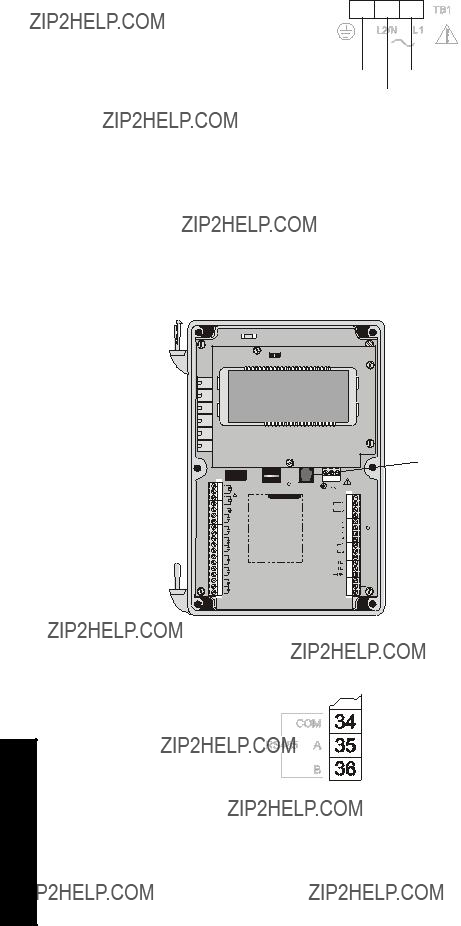
Note: Make sure unit is connected to a reliable ground.
Ground
GND L1
L2/N
Digital Communications
Wiring the MultiRanger for communications allows it to be integrated into a full SCADA system or an industrial LAN.
The MultiRanger can also be directly connected to a computer running Dolphin Plus.
mA INPUT
SHIELD
Connector
Connection (see below)
Wiring
Discrete Inputs
Discrete inputs have a positive and negative terminal. Requires an external power supply.
Discrete Input (post.) 1
Discrete Input (pos.) 2
Common (neg.) for Discrete Input
Wiring

Operation
Operating the MultiRanger
The MultiRanger has two modes of operation: RUN and PROGRAM.
RUN Mode
In RUN mode, the MultiRanger detects material level and provides control functions. The MultiRanger automatically starts in RUN mode when power is applied.
System status is shown on the unit???s LCD, or on a remote communications terminal.
Display

Icons indicating index type (Item 1) edited in PROGRAM mode:
Readings in RUN Mode
Change the displayed values with the keys on the hand programmer. All readings are shown in the Auxiliary field, except for the totalizer and P920.
Operation
Key


 +
+ 


 +
+ 


 [MR 200 only]

 [MR200 only]
 [MR 200 only]
+ ###
P
P


1.Distances less than 0.3 m (1 ft) from the transducer face cannot be measured reliably. Therefore, a 0% reading is not possible during Distance operation.
2.If the associated relay is programmed for pump control.

Operation

Controlling the Display
RUN mode provides numerous parameters and variables that you can track on the display (see Display on page 22).
The LCD displays EEEE if a value is too long.
Adjusting the primary reading for
Example
To reference the displayed level to sea level, enter the distance in Units (P005), between Empty (P006) and sea level. (Enter a negative value if Empty is below sea level.)
P062 is the distance between sea level and Empty.
Auxiliary Reading
The Auxiliary Reading area of the LCD displays parameter values while leaving the primary reading on screen.
Note: The parameters shown in the auxiliary reading field are indexed as follows:
???global
???by transducer
???by level
Operation

Operation
Setting the Default Auxiliary Reading
To maintain a constant variable display in the auxiliary reading area, set the default.
Example:
To leave the level reading on the screen and view the echo confidence in the auxiliary reading field, set the following parameter:
Multiple Readings [MR 200 only]
During differential or average operation (P001 = 4 /5), the display scrolls sequentially through Point Numbers 1, 2, and 3. Point 3 is the difference between (or average of) Points 1 and 2.
Changing Number Scrolling Speed
See Parameter Indexing on page 37. All the instructions in the following procedures apply to the hand programmer and assume that the MultiRanger is activated.
PROGRAM Mode
The MultiRanger is programmed by setting its parameters to match your specific application. Most parameters are indexed, allowing you to set the parameter to specific conditions and to more than one input or output. When the MultiRanger is in PROGRAM mode, you can change these parameter values and set operating conditions.
Please refer to the Parameter Reference section on page 117 for a full listing and explanations of parameter values.
The MultiRanger???s primary programming is by the hand programmer. Other access is available through Dolphin Plus software (purchased separately).
Notes
???To activate PROGRAM from RUN mode, press PROGRAM
 and then
DISPLAY 
???The display briefly reads
???Placing a programmed unit that is in normal operation into PROGRAM mode
Starting PROGRAM Mode
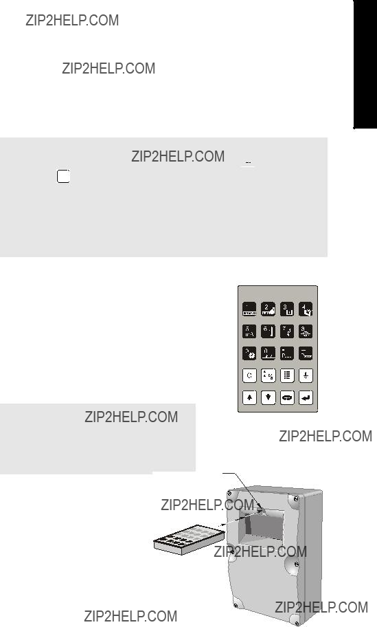
Hand Programmer
The hand programmer gives you direct access to the MultiRanger.
Aim the hand programmer and press PROGRAM key.
Notes:
???The battery in the programmer is not replacable.
???The hand programmer is ordered
Operation

Operation
Programmer Keys
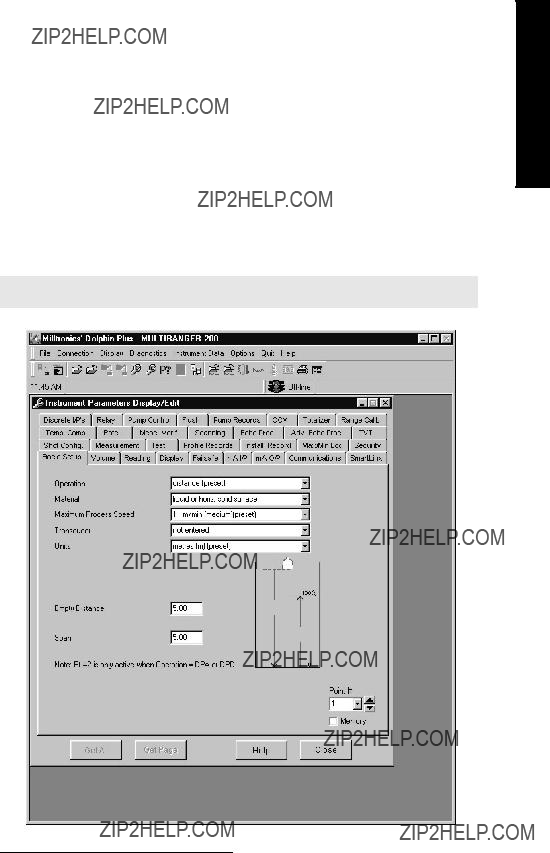
Dolphin Plus
(compatible with product software versions 1.06 and earlier)1
Use Dolphin Plus software to configure, monitor, tune, and diagnose the MultiRanger from a PC or directly in the field with a laptop.
Dolphin Plus is easy to install and easy to use. Just load the software from the CD onto a desktop PC or Laptop and then set up or modify complete parameter configurations in a Windows??2environment.
After configuration, you can edit parameters, upload and download parameter sets to and from disk, and use parameter sets saved from other instruments. You can also work with echo profiles for fine tuning without the need for special instruments.
Start features and Help files guide you through the entire process.
Note: Dolphin Plus is ordered separately from Siemens Milltronics.
1.See P900 for Software Revision Number.
2.Windows is a registered trademark of Microsoft Corporation.
Operation
Operation
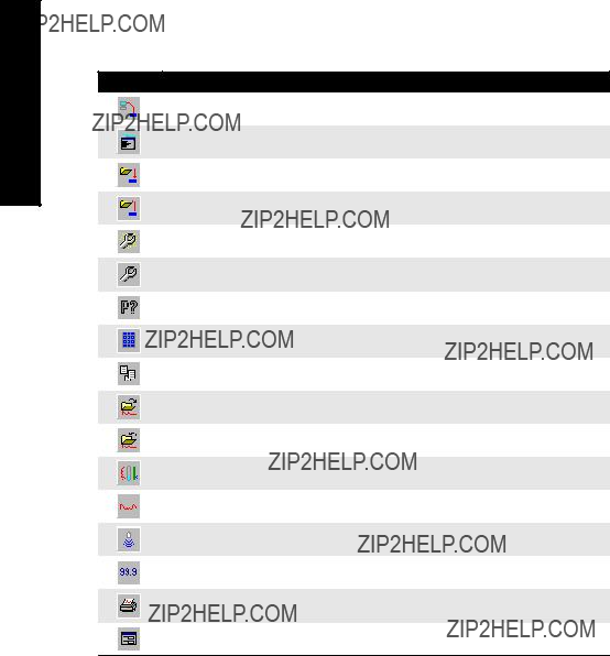
Dolphin Plus Toolbar Buttons
The toolbar buttons provide quick access to Dolphin Plus features.
Button Action
communicate with
send parameter set to instrument save parameter set to file
open the quick start wizard
open the tabbed parameters window
find a parameter in the tabbed parameters window toggle PROGRAM mode and RUN mode
open the reporting windows load an echo profile from a file
save the current echo profile to a file
open the vertical echo profile and tank mimic window open the horizontal echo profile window
take a measurement with the current transducer
open the reading values (distance measurement) window print current echo profile
open the Echo Info Editor window
SIMATIC Process Device Manager (PDM)
(compatible with product software versions 1.07 and later)1
SIMATIC PDM is a software package for parameterizing, commissioning, diagnosing and maintaining process devices. For the MultiRanger 100/200, SIMATIC PDM connects directly to the device using Modbus over Port 1 or Port 2.
The MultiRanger 100/200 comes with Port 1 set for communications to SIMATIC PDM.
SIMATIC PDM contains a simple process monitor of the process values, alarms and status signals of the device. Using SIMATIC PDM you can
???display,
???set,
???change,
???compare,
???check the plausibility of,
???manage, and
???simulate
process device data.
More information about SIMATIC PDM is available at www.siemens.com/processinstrumentation: go to Products & Solutions > Products & Systems > Communication and Software > Process Device Manager. Please consult the operating instructions or online help for details on using SIMATIC PDM. An Application Guide on using MultiRanger 100/200 with PDM and Modbus is available on our website: www.siemens.com/processautomation.
Device Description
To use Process Device Manager (PDM) with MultiRanger 100/200, you need the Device Description for MultiRanger 100/200, which will be included with new versions of PDM. You can locate the Device Description in Device Catalog, under Sensors/Level/ Echo/ Siemens Milltronics. If you do not see MultiRanger 100/200 under Siemens Milltronics, you can download it from our website: www.siemens.com/processautomation. Go to the MultiRanger product page and click Downloads. After downloading the DD file, you need to execute DeviceInstall.
1. See P900 for Software Revision Number.
Operation

Operation
Activating the MultiRanger
All the instructions in the following procedures apply to the hand programmer and assume that the MultiRanger is activated.
1.Power the MultiRanger.
2.Point the programmer at the unit and press PROGRAM 
 .
.
3.Press DISPLAY 
 .
.
Note: Power up display
???Single Point Model
???preset to display distance from the face of the transducer to the material
???transducer selection is preset for the
???empty distance is preset to 5 m
???Dual Point Model
???starts in an OFF state and does not take level measurements
???to set up measurement, the quick start parameters must be configured
???See Quick Start parameters on page 119
Changing Parameters
Note: If Parameter Value alteration is not permitted, access the Lock parameter (P000) and enter the security code, (see Security below).
1.Starting in RUN mode, press PROGRAM 
 and then press DISPLAY
  to put the unit into PROGRAM mode.
2.Press DISPLAY  to select the Parameter Number field.
3.Enter the Parameter Number (e.g. 110). After the third digit is entered, the parameter value is shown.
4.Enter the new value, and press ENTER 
 . The MultiRanger interprets the value, either accepting or replacing it with a valid value.
Helpful Hints
???For parameters P001 to P009, press a single digit  to show that parameter.
???The ? icon indicates that the MultiRanger has accepted the value but that it conflicts with other values entered.
???By default, the SCROLL arrows 


 show only the Quick Start parameters and any that have been changed.
???P733 sets all parameters to be

Security
The Lock parameter P000 secures the MultiRanger against parameter changes via the handheld programmer. The unit can still be put into PROGRAM mode when locked, and parameter values can be viewed, but no parameter values can be changed.
When P000 is set to 1954, programming is enabled. To disable programming, enter another value.
P000 (1954) is a fixed value password. Therefore, you should use other means to secure the MultiRanger if security is a concern.
Simulation
P000 Lock also controls how simulations affect control relays. By default, control relays are unaffected by simulation levels. But if P000 is set to
Using Units or Percent (%)
Many parameters can be viewed either in measurement units (P005) or as a percentage. View the parameter and then press MODE  to toggle between units and percentage. The LCD shows the selected measurement type, either units (m, ft) or percentage (%).
MR 200 only:
Percentage is also available when showing flow and volume with 100%, based on the parameter that defines the maximum.
Parameters Types
View Only Parameters
Parameter values indicating status only. They cannot be altered.
Global Values
Parameter values common to all inputs and outputs on the MultiRanger.
When a global parameter is accessed, the index display automatically disappears. When a
Operation

Operation
Default Values
Parameter default values are indicated with an * in the parameter tables.
The asterix identifies 1954 as the default value.
Parameter Reset
Returning a parameter to factory default.
1.Display the appropriate parameter number.
2.Display the appropriate index value (if required).
3.Press CLEAR 
 .
.
4.Press ENTER 
 .
.
Master Reset (P999)
Returns all parameters to original values.
Use Conditions:
???before initial system installation
???following a software upgrade
If complete reprogramming is required, use Dolphin Plus to store and retrieve parameters.
When the dual point option is enabled, P999 is indexed by transducer. Use index 00 to reset the entire MultiRanger.
Display Readout
The following readouts are shown when the MultiRanger cannot display a number.
Display Definition
Parameter has not been set
All values not same when viewing index 0
Value too large for

Changing Parameters(Dolphin Plus)
The other method for changing parameter values is with Dolphin Plus software. It lets you access the MultiRanger from a PC or on site with a laptop and change MultiRanger parameters.
Most examples in this manual use the icons from the hand programmer but nearly all functions are also available through Dolphin Plus.
Operation
Operation
Parameter Indexing
Parameters are indexed when they apply to more than one input or output. The index value defines the input/output for that parameter. Indexed parameters contain a value for each index, even if that index is not used.
MultiRanger Display
The index number and the index values are displayed above the parameter indicator on the LCD.
Notes
???Transducers are always indexed when the dual point option is enabled.
???An indexed transducer is commonly referred to as a Point (short for ???Measurement Point???). Point Number refers to indexed transducers.
???To set all indexed values for a parameter to the same value, use index 0.
???MR 200 only: Transducer parameters are indexed only if Operation (P001) is set to Difference (value=4) or Average (value=5) on a single point MultiRanger.
Accessing a Parameter Index
1.Press DISPLAY  once to clear current parameter field.
2.Enter the new parameter number.
3.Press DISPLAY  twice.
4.Press the number of the required index. Or press ARROW keys 


 to scroll through the available values.
Note: For optimum performance, set values accurately for indexed parameters. Ensure that the correct index value is being changed for each parameter value.

Primary and Secondary Indexes
Primary Index: relates to direct input or output and can refer to relays, communications ports, and other parameters. In parameters that allow secondary indexes, the primary index is often referred to as a point.
Secondary Index: relates to previously indexed parameters where the parameter requires a second index, permitting multiple values on an indexed input or output.
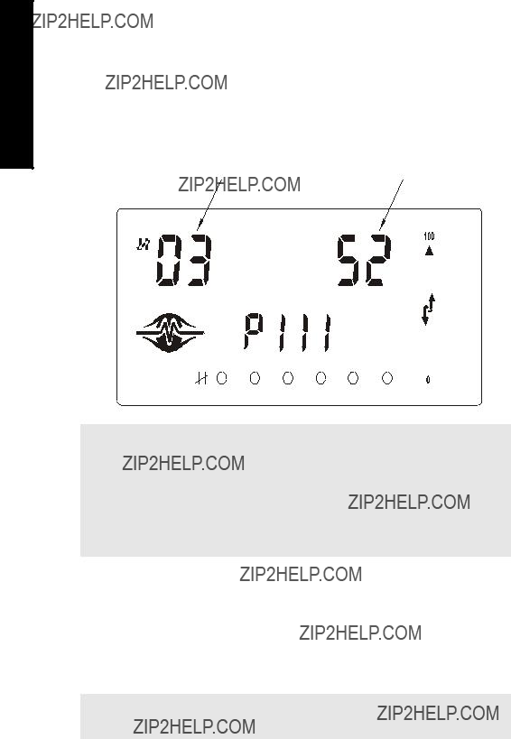
Primary Index
Example Setting: P111[3] = 52
P111
Operation
52
???P111 sets the Relay Control Function
???P111(3) = 52 sets Relay #3 to a value of 52.
Secondary Index
Parameters with a secondary index permit multiple values for a primary index (point). For example, a volume calculation based on vessel characterization breakpoints requires a distinct set of breakpoints for each measured point.
Thus the primary index refers to the measurement point, and each secondary index refers to a characterization breakpoint value.
Accessing a Secondary Index
1. Press MODE 

 and then press DISPLAY
  to activate secondary index. The

 icon appears under the index field.
2.Enter the secondary index, and then enter the values to set the secondary index.
Operation
Example [MR 200 only]
P054 provides up to 32 breakpoint levels used with P055 (Volume Breakpoint) for universal volume calculation. The illustration indicates how you can set secondary indexes to specific functions.
???P054 [1,1] = .75m sets breakpoint 1 on transducer 1 to .75m.
???P054 [2,1] = 8m sets breakpoint 1 on transducer 2 to 2.75m.
Starting Measurement
The MultiRanger startup varies between single and dual point models.
Note: The number of points is an order option and is set by the factory. On a single point model, the index for P001 is global (G). On a dual point model the index for P001 is 1 or 2. To check the model in use, enter P001 on handheld programmer. For a single point device, parameter P001 will not show an entry for index number on the LCD. (See MultiRanger Display on page 36 for location of index number on the LCD.) Parameter P001 will display an index number for a dual point model.
Single Point Models
The MultiRanger starts in DISTANCE mode with the transducer preset for the

Average or Differential [MR 200 only]
For differential or average operation with a
transducers of the same type. All of the relevant 3 parameters then become indexed by the correct transducer:
Operation
Index Description
2indexed by Transducer One or Two
3indexed by level measurement 1 = Transducer One
2 = Transducer Two
3 = Calculated Level (average or difference)
Dual Point Models
The MultiRanger starts in an OFF state and does not take level measurements. For measurement setup, configure these basic parameters:
If the application uses two measurement points, provide the basic information for each measurement point separately:

Operation
Average or Differential [MR 200 only]
For differential or average operation
All the relevant parameters are then indexed by the correct number:
Index Description
2indexed by Transducer One or Two
3indexed by level measurement 1 = Transducer One
2 = Transducer Two
3 = Calculated Level (average or difference)
Measurement Conditions
The following information will help you configure your MultiRanger for optimal performance and reliability.
Response Rate
The response rate of the device influences the measurement reliability. Use the slowest rate possible with the application requirements.
The response rate is also important to functions connected to the filling or emptying indicators.
Dimensions [MR 200 only]
The dimensions of the vessel, wet well, or reservoir (except empty and span) are only important if you require volume.
Volume is required to report the level value in terms of volume. The pumped volume function can also report pumped volume or pump efficiencies.
Failsafe
The failsafe parameters ensure that the devices controlled by the MultiRanger default to an appropriate state when a valid level reading is not available.
???P070 ??? Failsafe Timer activates if an error condition is detected. Upon expiration of the timer, relay status defaults to values based on P071.
???P071 ??? Failsafe Material Level determines the level reading if the Failsafe Timer expires and the unit is still in an error condition.
???P129 ??? Relay Failsafe controls the reaction of each relay. See Relay Failsafe on page 45 for more information.
If Failsafe Operation activates frequently, see the Troubleshooting Appendix on page 231.
Relays
Relays are the primary controls of external devices such as pumps or alarms. The MultiRanger comes with extensive control and alarm functions.
General Introduction
Depending on the model, up to six onboard
The relay functions fall under three modes of operation:
Relay Function
Note: The MultiRanger 100 or 200 can be programmed with relays. The number of relays installed depends on the model. To determine the number of available relays that can be utilized in your MultiRanger 100 or 200, open the lid and count the large white relays to the left of the display. It is important to count the number of
Alarm
Level
In high alarm, the function goes on when the level rises to the ON setpoint and goes off when the level lowers to the OFF setpoint. In low alarm, the function goes on when the level lowers to the ON setpoint and goes off when the level rises to the OFF setpoint.
In Bounds [MR 200]
The relay will be in alarm if the level is inside the zone between the setpoints.
Out of Bounds [MR 200]
The relay will be in alarm if the level is outside the zone between the setpoints.
Rate of Change [MR 200]
In filling alarm, the function goes on when the rate of filling increases to the ON setpoint and goes off when the rate of filling drops to the OFF setpoint. In emptying alarm, the function goes on when the rate of emptying increases to the ON setpoint and goes OFF when the rate of emptying drops to the OFF setpoint. For emptying alarm, the setpoints must be entered as negative values.
Relays

Relays
Temperature [MR 200]
In high alarm, the function goes on when the temperature rises to the ON setpoint and goes off when the temperature lowers to the OFF setpoint. In low alarm, the function goes on when the temperature lowers to the ON setpoint and goes off when the temperature rises to the OFF setpoint.
Loss of Echo
The function goes on when the
Pump
Level
In pump down, the function goes on when the level rises to the ON setpoint and goes off when the level lowers to the OFF setpoint. In pump up, the function goes on when the level lowers to the ON setpoint and goes off when the level rises to the OFF setpoint.
Miscellaneous
Totalizer and Samplers [MR 200]
Refer to Totalizing Pumped Volume on page 65. Relays are normally
Setpoint - ON / OFF
If the ON setpoint is higher than the OFF setpoint, the relay operates as:
???high alarm
???pump down control
If the ON setpoint is lower than the OFF setpoint, the relay operates as:
???low alarm
???pump up control
The ON and OFF setpoints can not be the same on an individual relay but may be common to other relays. The dead band or hysteresis is the difference between the ON and OFF setpoints. For in and out of bounds level alarms, the hysteresis is set at ?? 2 % of span from either boundary.

Relay Status ??? Non Run Modes
When the
Upon entering the program mode, all pump control relays will be turned OFF. Alarm relays will hold their prior status.
Relay States
The relays on the MultiRanger are completely programmable, allowing for any control scheme.
Relay Types
Relay 1,2,4,5 ??? NO (Form A)
Relay 3,6 ??? NO / NC (Form C)
Relay Related Parameters
Some parameters affect how relays react during normal conditions:
Sets the MultiRanger to a preset application. These preset applications quickly set up the MultiRanger with a minimum number of parameters.
Sets the default state differently, depending on whether the relay is programmed as an alarm or a control.
The alarm function

Relays
The control function energizes the relay coils. When the instrument is at rest (no controls operating) the relay coils are de- energized.
Sets the process point at which the relay is tripped.
Sets the process point at which the relay is reset.
Affects relay reaction. Reverses the logic
Changes how individual relays react to a failsafe condition on the instrument.
Relay Wiring Test
Checks the application wiring by forcing a relay control function, such as a level alarm or pump control setpoint. Ensure all the relay programming and wiring works properly.
Please verify that ON and OFF respond correctly. Use P119 as a final test once all of the relay programming is done.
Relay Activation
The flexibility of the relay functions ensures that the MultiRanger can support relay wiring for different systems and applications. Use the following as a guide to the most common parameters.
Relay Setpoints and Functionality
[MR 100]: When a setpoint is reached, the corresponding action is taken. The setpoint can be an ON or OFF setpoint related to a process variable.
[MR 200]: The setpoint can be an ON or OFF setpoint related to a process variable, or a timed setpoint based on interval and duration.

[MR 100]: Functions affected by setpoint are configured by parameters that determine the application requirements such as timing. P111 Pump and Control functions (see page 134) sets the functions requirements.
[MR 200]: Functions affected by setpoint are configured by parameters that determine the application requirements such as timing. P111 Pump and Control functions (see page 134 sets the function requirements. Other function parameters:
???
???
???
Relay Logic is Modified
Normal operating conditions means that alarms are off and pumps are on. This can be reversed using
Relay Failsafe
Adjusts how individual relays react to a failsafe condition. Relays can be set to:
Relays
Preset Applications
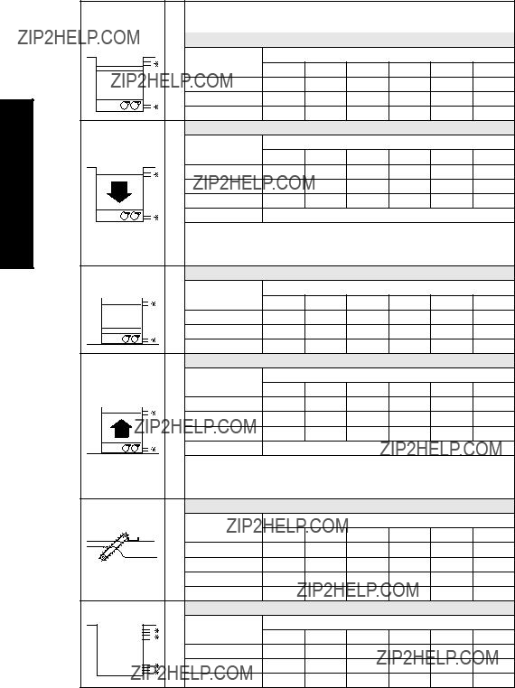
Preset applications set up the relay parameters to predetermined values shown below:
Relays

Backup Level Override
Backup level override provides the option of overriding the ultrasonic input with another contacting point level device, for example, the Pointek CLS200. The ultrasonic reading is fixed at the programmed switch level until the discrete input is released and the ultrasonic device makes its decisions based on the override value.
Backup Level Override Parameters
P064: Reading Override Enable
Sets the discrete input as the source of a level reading override.
P065: Reading Override Value
Substitutes value for current reading when the discrete input (P064) is enabled. Value is added in current units and is valid only for the following:
???level
???space
???distance
???difference
???average modes of operation
???head level in OCM mode
Example:
A high level backup switch is connected to Digital Input Two in the same application as Transducer One at level value 4.3 m.
Settings
When the level rises to 4.3 m and the switch is activated, the reading is forced to 4.3 m where it stays until the switch is
P066: Override Time Delay
Sets the time (in seconds) used to calm the override condition input.
Override Level Backup

Discrete Inputs
Discrete Inputs
Wiring the Discrete Inputs
Normal state is standard operation, with the MultiRanger sensing the material level and controlling the pumps.
The discrete input contacts are either
Example:
Normal state for a backup high level switch is open, and the contacts on the discrete input are wired as
See Discrete Inputs on page 21 for complete details on wiring the discrete inputs. To override a level using a discrete input, see Backup Level Override on page 47.
Programming the Discrete Input Logic
The P270 series of parameters permits control over the discrete input.
The current value of the discrete input is reported in P275:

mA I/O
To integrate the MultiRanger with other equipment, use the mA input and outputs.
Note: When a mA input parameter is accessed, a mA symbol appears in the upper left corner of the LCD display.
The mA input can be used as a level measurement or can be passed on to a SCADA system.
mA Input [MR 200]
Level Reading Parameters
To pass the mA input on to a SCADA system, read the value from the appropriate communication registers. For more information, go to the MultiRanger Communications section on page 89.
mA Output
The MultiRanger has two mA outputs, used to send measurements to other devices.
Configuring the mA output to send a 4 to 20 mA signal scaled from 10% to 90% of span of the second transducer:
1.If the level reading drops below 10% of span, the mA output drops below 4 mA.
2.If the level reading rises above 90% of span, the mA output rises above 20 mA.
I/O mA

Calibrating 4 mA Output
1.Connect the mA receiving device to the MultiRanger.
2.Put the MultiRanger into PROGRAM mode.
3.Set
4.View the mA level on the receiving device.
5.If there is a discrepancy,
a.Attach ammeter to MultiRanger mA output.
b.Access P214, Index 1 (for mA output 1) or 2 (for mA output 2). Press CLEAR and
ENTER 
 . The ammeter should show a value near 4 mA. c.Enter the exact value displayed on the ammeter into P214 (Index 1 or 2). d.The ammeter should then read exactly 4.00 mA.
The unit is now calibrated for 4 mA for the receiving device.
Calibrating 20 mA Output
1.Connect the mA receiving device to the MultiRanger.
2.Put the MultiRanger into PROGRAM mode.
3.Set
4.View the mA level on the receiving device.
5.If there is a discrepancy,
a.Attach ammeter to MultiRanger mA output.
b.Access P215, Index 1 (for mA output 1) or 2 (for mA output 2). Press CLEAR and
ENTER 
 . The ammeter should show a value near 20 mA. c.Enter the exact value displayed on the ammeter into P215 (Index 1 or 2). d.The ammeter should then read exactly 20.00 mA.
The unit is now calibrated for 20 mA for the receiving device.
Verifying the mA Range
Checks that the external device can track the entire 4 to 20 mA range sent by the MultiRanger.
1.Use P920 to put the MultiRanger into Simulation mode (see page 85).
2.Run the simulation through one complete fill / empty cycle.
3.View
4.View the mA value reported on the external equipment to verify that it also tracks to the simulation.
mA LI/O
Volume [MR 200]
Volume is a feature of the MultiRanger 200 only. Volume is used in two situations:
1.Calculate and display volume instead of level. For programming all setpoint parameters in terms of volume units rather than level units.
2.Calculate pumped volume to accomplish the following:
???Totalize the volume of material that is pumped out of the wet well
???Set an alarm on pump efficiency
If you require this functionality, please contact your local Siemens Milltronics representative at www.siemens.com/processautomation .
Readings
When using volume, readings are given in arbitrary units specified in P051.
The default is 100, which gives a reading in percent of total. Use whatever units you want here. If the value is too large for the
Example
If a wet well has a maximum capacity of 250,000 liters, use the value 250.0 for P051 and set the reading in 1000s of liters.
Tank Shape and Dimensions
There are many common tank shapes to select from. (See P050. If possible, use one of these.) Each tank shape uses the Empty distance (P006) in its calculations of volume.
Some tank shapes also require extra dimensions to calculate the volumes. Do not estimate these values. They must be correct to ensure the accuracy of your volume calculations.
To configure volume for a tank with a
Notes:
???The default reading changes to a range from 0 to 100 (the value in P051)
???Empty (P006) is still measured to the bottom of the tank, not the top of A.
Volume

Volume
Characterization Chart [MR 200]
If you cannot use a
1.Plot a volume to height chart. Usually a tank supplier will provide this chart. However, if you have a
2.Enter the curve values from this chart into P054 and P055.
3.Ensure extra points are added around sharp transitions in the wet well volume (e.g: as steps in the well wall).
Note: The end points in the curve are 0,0 (fixed) and the point defined by P007??? Span and
Example Chart
MAX VOLUME
P051
VOLUME (P055)
FLOW

Alarms
Level
The level alarm is the most common. Use this alarm to warn you when your process is in danger of being upset due to high or low levels.
Generally, the four alarms used are Hi, Hi Hi, Lo, and Lo Lo.
Set the Common Parameters
Alarms
Prerequisite: You must know the details of your application and substitute the values for the sample values provided. If you are bench testing the unit, then set your test values to be the same as the sample values.
1.This example assumes a base, single measurement unit. If your unit has optional dual point software installed then some parameters are indexed by two.

Setting Simple Level Alarms
To set Relay Five to a standard level alarm (Hi Hi, Hi, Lo, Lo Lo) do the following:
Available designations:
Rate [MR 200]
Rate alarms can trigger an alarm if the vessel is filling/emptying too quickly.
Setting a Filling Rate Alarm
Alarms

Alarms
In Bounds/ Out of Bounds Range [MR 200]
Use the bounded range alarms to detect when the level is inside or outside of the range. By using a bounded range alarm, you can effectively put two level alarms (high and low) on one relay.
Setting an Out of Bounds Alarm
Results:
???Trips alarm above 1.35 m and below 0.25m
???Resets alarm below 1.25 m and above 0.35m
Setting an In Bounds Alarm
Results:
???Trips alarm below 1.25 m and above 0.35 m
???Resets alarm above 1.35 m and below 0.25 m
Cable Fault
Activates an alarm if transducer cable circuit enters a shorted or opened state.
Temperature [MR 200]
Use the temperature alarm to activate an alarm when the temperature reaches the ON setpoint (P112). This alarm uses the same setpoint parameters as the level alarms (P112 and P113).

With P112 and P113, you can set a high alarm (P112 > P113) or a low alarm (P112 < P113).
This shows a high alarm:
The temperature source can be the temperature sensor built into the transducer or an external
Loss of Echo (LOE)
Alarms

Pump Control
Pump Control
Setting a Pump Down Group
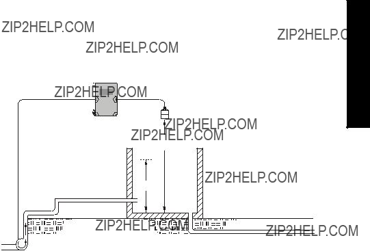
Example: Sewage Wet Well
Setting a group of three pumps to pump down a wet well.
MultiRanger
P006
Outflow
Set the Common Parameters
Prerequisite: Substitute the details of your application in place of the sample values provided. If you are bench testing the unit, set your test values to be the same as the sample values.
1. Example assumes a single measurement unit. If your MultiRanger has dual point software installed then some parameters are indexed by two.
Set Relays to ALTERNATE DUTY ASSIST
Setting a Pump Up (Reservoir) Group
Sets a group of three pumps to pump up a reservoir.


 MultiRanger
Control Pump
Inflow 


P006
P007
Outflow 


Pump Control
Set the Common Parameters
Prerequisite: Substitute the details of your application in place of the sample values provided. If you are bench testing the unit, set your test values to be the same as the
sample values.
1. Example assumes a single measurement unit. If your MultiRanger has dual point software installed, some parameters are indexed by two.
Set Relays to ALTERNATE DUTY ASSIST
For more information, see Appendix D: Pump Control Reference on page 239.
Other Pump Control Algorithms
Set Relays to ALTERNATE DUTY BACKUP [MR 200]
Set Relays to FIXED DUTY ASSIST
Control Pump

Pump Control
Set Relays to FIXED DUTY BACKUP [MR 200]
Set Relays to ALTERNATE DUTY SERVICE [MR 200]

Set Relays to FIRST IN FIRST OUT (FIFO) ASSIST [MR 200]
Optional Pump Controls
Starting Pumps by Rate of Level Change [MR 200]
Use this function when multiple pumps will be controlled by rate of level change rather than setpoints. Pumping costs can be reduced because only the highest ON setpoint needs to be programmed. This results in a lower difference in head to the next wet well which, in turn, results in less energy being used to pump out the well.
Control Pump

Pump Control
When the first ON setpoint is reached, the pumps will start, one by one, until the material level rate of change is set at the same value or greater than the value in:
???P703 ??? Emptying Indicator (pump down applications)
???P702 ??? Filling Indicator (pump up applications)
Set delay between pump starts using P132 ??? Pump Start Delay.
Single and Dual Point [MR 200]
???Single Point Mode: one pump by rate control available that affects all pumps.
???Dual Point Mode: a single pump by rate control can be set up for each of the three available level points. Set Operation for difference or average (P001 = 4 or 5).
Notes:
???Set all pump control relay ON and OFF setpoints to the same value
???If the level is within 5% of Span (P007) of the OFF setpoint, then the next pump is not started
Rotating Pumps by Service Ratio [MR 200]
Prerequisite: Set pump relays to a service ratio value (P111 = 54 or 55).
Notes:
???The MultiRanger will not sacrifice other pumping strategies to ensure that the ratio is held true
???If the pump relays are set to the same value, then the ratio equals 1:1 and all pumps are used equally (preset)
When more than one pump is assigned a Pump Service Ratio value (in any time units) and a pump start is required (P112 Relay Setpoint ON), the pump with the fewest running hours (with respect to the assigned ratio values) starts.
Conversely, when a pump stop is required (113 Relay Setpoint OFF), the pump with the most running hours (as compared to the assigned ratio values) stops.

Totalizing Pumped Volume [MR 200]
Prerequisite: the volume of the vessel must be known.
Set in RUN Mode
1.Press PROGRAM 
 for RUN mode.
2.Press TOGGLE 
 to display pumped volume on the totalizer.
3. Press AUXILIARY P to display current level in the auxiliary reading area.
Setting Independent Failsafe Controls
Independent failsafe controls allow you to vary an individual relay from the global failsafe controls programmed in P070 to P072.
Example:
The global failsafe controls are set to hold and Relay Five is set to trigger an alarm bell.
Control Pump

Pump Control
Setting a Pump to Run On [MR 200]
When you need to pump below the normal OFF setpoint, use P130 (Pump
Example:
The pump connected to Relay Three is set to pump for an extra 60 seconds every 5 hours.
Note: P130 counts when the indexed relay is tripped, not the number of pump cycles. If the indexed relay only trips once every four pump cycles then the actual interval of the
Setting the Pump Start Delays [MR 200]
The pump start delay ensures that all of the pumps do not start at once to avoid power surges. There are two parameters used here:
Example:
The delay between pumps is set to 20 seconds and the delay of the first pump is set to 30 seconds.
Reducing Wall Cling [MR 200]
Use the Wall Cling parameter to randomly alter the ON and OFF setpoints over a range. This eliminates the ridge of material that builds up at the setpoint that can give false echoes.
This setting may increase the number of days between trips to clean the wet well.
Wall cling reduction is set by P136. The relay setpoints ON and OFF are randomly varied inside a range so the material level does not stop at the same point.

Example [MR 200]:
A range of 0.5 meters is used to vary the setpoint. The
Grouping Pumps [MR 200]
You can group pumps and use the same pumping algorithm separately on each group. If you specify different pumping algorithms then the pumps are already grouped by algorithm and you do not need to use this parameter.
Group pumps only when four pumps are using the same algorithm and you want to split them into two groups.
Example:
Pumps One and Two can operate as a group and Pumps Three and Four can operate as another group.
Setting a Flush Valve [MR 200]
A flush valve stirs up the sediment on the bottom of the well during pumping so that it doesn???t accumulate. These parameters will control any relays set with P111 = 64 (Flush Valve).
Most sets of parameters will work with only one or two changes; however, for these parameters to work, all of them must be set to a value.
Control Pump

Pump Control
Example:
The flush valve connects to Relay Four and the watched pump is on Relay One.
Relay Controlled by Communications
A relay can be controlled directly by a remote system through communications. No other control schemes can then be used with a relay configured this way. Communications can be used to force status of some control relays, such as pumps.
Settings:
Tracking Pump Usage
You can find out how much an individual pump has been used by viewing the pump records parameters.

Rake (Screen) Control [MR 200]
This feature is only available on the MultiRanger 200.
Screens or rakes are mounted on the inflow channel of the wastewater treatment plant to prevent debris from clogging the equipment.
When material builds up on the screen, a level differential is created, and the water level is higher in front of the screen than behind it. When this differential reaches the programmed setpoint, the MultiRanger activates a relay to operate mechanical rakes that clean the screen and ensure a steady flow.
Setting a Rake Control
P007 (3)
Max differential between Point 1 and Point 2 reading also sets 100% scale for bargraph and mA output.
Control (Screen) Rake
200 MR
Setting the Common Parameters
Prerequisite: Substitute the details of your application in place of the sample values provided. If you are bench testing the unit, set your test values to be the same as the sample values.
Set Relay 1 (Operate Rake)
Set Relays 2 to 4 (Level Alarms)
External Totalizers and Flow Samplers [MR 200]
This feature is only available on the MultiRanger 200.
External totalizers are simple counters which count the number of relay clicks produced by the MultiRanger. This is generally used to keep track of OCM or pumped volume totals. Note that both of these values are also stored in the MultiRanger and are available through communications.
Flow samplers are devices which take a sample of liquid when triggered by a relay click. These samples are used to monitor water quality over time. Flow samplers can be driven by OCM volume or by relay click volume settings depending on the application requirements.
Relay Contacts
Pumped volume is calculated at the end of the pump cycle. Totalized volume given through a relay set up for totalizer (P111[r]=40) will be given in bursts at this time.
Both the open and closed times for the relay contact are provided by P645 and are preset to 0.2 seconds. Partial units are added to the next pump cycle.
Example:
Shows a relay set up to make one contact for every cubic metre (m3) of liquid.
Pump Cycle
Totalizer
To set the totalizer to provide relay contact to an external counter, use the following:
and Totalizers External
200 MR ??? Samplers Flow

The source of units depends on the operation:
Flow Sampler
Based on Volume and Time
To trigger a flow sampler relay based on flow, use P111[r]=41 and set the other parameters:
Counter Formula
1 Contact per P641 x 10P642 units
By using a mantissa (P641) and an exponent (P642), the relay contacts can be based on a volume other than a multiple of ten.
During the periods of low flow, the sampler may be idle for lengths of time. Program P115 to a time interval in hours to drive the sampler. The sampler will operate based on the volume of flow or the time interval, whichever comes first.
Flow Samplers ??? MR 200
External Totalizers and

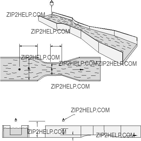
Open Channel Monitoring (OCM) [MR 200]
An OCM installation is defined one of three ways, based on the Primary Measuring Device (PMD):
1.Dimensional (P600 = 2,3,6,7)
For some common weir and flume types. PMD dimensions (P602) are entered directly.
???
???
???Palmer Bowlus Flume on page 77
2.Exponential (P600 = 1)
For most other weir and flume types. PMD exponents provided by the manufacturer are entered. Flow is calculated using the exponent (P601) and the maximum values (P603 and P604).
???Standard Weirs on page 79
???Parshall Flume on page 80
???Leoplod Lagco on page 81
???Cut Throat Flume on page 82
3.Universal (P600 = 4,5)
For all other PMDs, the
???Typical Flow Characterization on page 83
???Example Flumes on page 84
???Example Weirs on page 84
Common Parameters
These Quick Start parameters are required for all installations.
Monitoring Channel Open
200 MR
Setting Zero Head
Many PMDs start flowing higher than the traditional empty distance of the application. You can account for the flow in one of two ways:
1. Use P605 (Zero Head) to have OCM calculations ignore levels below that value. Possible head = P007 minus P605.
Note: P603 (Max. Head) is preset to P007 and is not updated when P605 is used. Make sure you set P603 to the correct value when using P605.
P603
P006
P007
P605
2.Use P801 Range Extension where the Empty level is set to the bottom of the weir, and above the bottom of the channel. It should be used if the surface monitored can fall past the Empty (P006) level in normal operation without reporting an LOE. The value is added to Empty (P006) and can be greater than the range of the transducer.
The examples on the following pages show both methods.

Setting Totalized Volume
To display the totalized volume on the LCD use the following parameters:
Applications Supported by MultiRanger 200
Monitoring Channel Open
200 MR
4 to 5 x hmax (hmax = P007)
Plan View
Plan View 4 to 5 x hmax (hmax = P007)
L
Flow
Transducer
P006
P605 (p)
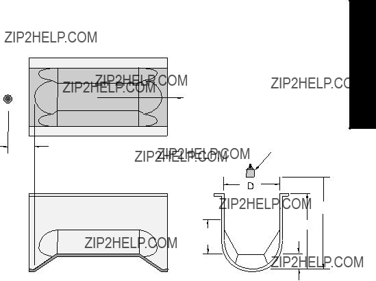
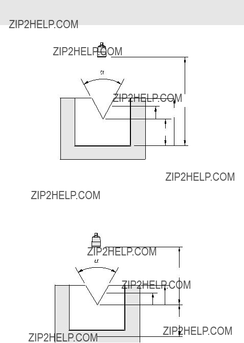
Palmer Bowlus Flume
Monitoring Channel Open
200 MR
Application Information
???Sized by pipe diameter D
???Flume relief is trapezoidal
???Designed to install directly into pipelines and manholes
???Head is referenced to bottom of the throat, not bottom of the pipe
???For rated flows under free flow conditions, the head is measured at a distance of D/2 upstream from the beginning of the converging section
H Flume
Transducer
Flow
???Sized by maximum depth of flume
???Approach is preferably rectangular, matching width and depth for distance 3 to 5 times the depth of the flume
???May be installed in channels under partial submergence (ratio of downstream level to head). Typical errors are:
???1% @ 30% submergence
???3% @ 50% submergence
???For rated flows under free flow conditions, the head is measured at a point downstream from the flume entrance
???H flumes come with a flat or sloping floor. The same flow table can be used because error is less than 1%.
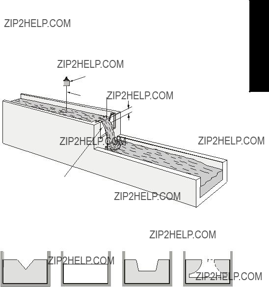
PMDs with Exponential Flow to Head Function
For Primary Measuring Devices (PMDs) that measure flow by an exponential equation, use these parameters. Ensure that you use the correct exponent for your PMD; the values below are samples only.
Standard Weirs
Transducer
3 to 4 hmax 
h
Weir Profile
Monitoring Channel Open
200 MR
Applicable Weir Profiles
1.Values are samples only. Consult weir manufacturer???s documentation for correct flow exponent.
Flows through these weirs can be measured using the Universal Flow Calculation P600 = 4 or 5. See Universal Calculation Support on page 83.
Parshall Flume
Note: C = Converging Dimension.
2/3 C
Flow
Transducer
P006
Application Information
???Sized by throat width
???Set on solid foundation
???For rated flows under free flow conditions, the head is measured at 2/3 the length of the converging section from the beginning of the throat section
Leopold Lagco Flume
Plan View
Throat
Front View
Application Information
???Designed to be installed directly into pipelines and manholes
???Leopold Lagco may be classed as a rectangular
???Sized by pipe (sewer) diameter
???For rated flows under free flow conditions, the head is measured at a point upstream referenced to the beginning of the converging section. Refer to the following table:
Monitoring Channel Open
200 MR
Cut Throat Flume
Plan View
Application Information
???Similar to Parshall flume except that the floor is flat bottomed and throat has no virtual length.
???Refer to manufacturer???s specifications for flow equation and point of head measurement.

Universal Calculation Support
When the primary measuring device (PMD) doesn???t fit one of the standard types, it can be programmed using a universal characterization. When Universal is selected as the PMD type (P600), then both P610 and P611 must be entered to define the flow.
Two curve types are supported:
???P600 =
???P600 =
Both are shown in the following chart.
Typical Flow Characterization
Characterization is achieved by entering the head (P610) and corresponding flow (P611), either from empirical measurement or from the manufacturer's specification. Increasing the number of defined breakpoints will increase the accuracy of the flow measurement.
Breakpoints should be concentrated in areas exhibiting the higher degrees of non linear flow. A maximum of 32 breakpoints can be defined. The curve???s end point is always specified by the parameters Maximum Head (P603) and Maximum Flow (P604) for a maximum total of 33 breakpoints.
Use as many breakpoints as required by the complexity of your PMD.
See Volume on page 51 for more information and parameters P610 and P611 for characterization.
Monitoring Channel Open
200 MR
Example Flumes
These example flumes would both require a universal calculation.
Trapezoidal
Dual Range (nested) Parshall
Example Weirs
These weirs could require universal calculation.

Testing the Configuration
After programming the unit, you must test the device to ensure that it performs to your specifications. This test can be run in simulation mode or by varying the level in the application. The latter is preferred as it more accurately represents running conditions. However, if it is not possible to do a physical test, a simulation will ensure that control programming is correct.
Simulation
In simulation mode, the LCD display reacts to the simulated level changes. Alarm relays will also react to the simulation, but any pump or control relays will not react.
To allow pump or control relays to operate on the simulated level, set P000 to
Simulating a Single Measurement
Access the appropriate parameter: (press PROGRAM  and then key in the parameter number). Press TRANSDUCER

 five times to overcome Echo Lock (P711) if applicable: the associated Reading is displayed in the Parameter Value field, and any alarm relays are set accordingly.
To verify Reading calculations (P920 to P926)
1.Go to the parameter to be simulated (P920, P921, P922, P923, P924, P925, or P926), and key in a material level in Units (Units defined in P005), or % of Span (% of Span defined in P007).
2.Press ENTER 
 to display the calculated Reading. [Regardless of setting for P001, the parameter value being simulated will display as the primary reading. The auxiliary reading will always display the level value (P921). See ???Display??? on page 22 for positions of the primary and auxiliary readings on the LCD.]
3.Verify the calculated Reading. (At this point, the simulation is in Stop state. The effect of the ARROW key is based on this state. See chart on page 86.)
Note: When you set P001 = 3 (Distance), span (P007) is preset to empty (P006), therefore the primary and auxiliary readings may display the same value when Space (P922) is being simulated.
Simulating a Level Cycle
Starting a (P920, P921, P922, or P923) simulation when level = 0:
1.Go to the parameter to be simulated (P920, P921, P922, or P923).
2.Press ENTER 
 to simulate level rise and fall. At the start of a simulation, the default rate is 1% of Span / second.
Configuration the Testing

Testing the Configuration
3.Press the ARROW  or
or  to adjust the simulated rate of rise or fall, based on the chart on page 86. The maximum rate is 4% of Span / second.
The effect of the ARROW key is determined by the state (rate of rise or fall) immediately before the key is pressed.
When the level rises to 100% or falls to 0%, it reverses direction at the same rate.
Checking Volume Characterization [MR 200]
To confirm universal volume calculations (P050 = 9, 10) are correct:
1.Go to P920.
2.Key in a level associated with a known volume.
3.Press ENTER 
 .
.
4.Check the returned volume against the manufacturer???s chart.
5.Change parameters P054 and P055, as required.
6.Repeat steps 2 to 5 until the volume curve is verified.
Checking OCM Flow Characterization [MR 200]
To confirm universal flow calculations (P600 = 4, 5) are accurate:
1.Go to P925.
2.Enter a level with a known flow.
3.Press ENTER 
 .
.
4.Check the returned flow against the manufacturer???s chart.

5.Change parameters P610 and P611, as required.
6.Repeat steps 2 to 5 until the flow curve is verified.
I/O Checkout
After the unit is installed, test to verify the wiring.
Relays
Use P119 to force a state change and verify that the results are as expected (pump starts, alarm sounds, etc.).
Discrete Inputs
Use P270 to force the input value and verify that the results are as expected.
1.Go to P270 [DI] where DI = the discrete input to be tested
2.Set P270 to 0 (forced OFF)
3.Go to P275 [DI] to verify that the value is forced
4.Check the state of outputs to ensure that they respond as expected
5.Go to P270 [DI]
6.Set P270 to 1 (forced ON)
7.Go to P275 [DI] to verify that the value is forced
8.Check the state of outputs to ensure that they respond as expected
For further information see Discrete Inputs section on page 48.
mA Input [MR 200]
Use P254 to test the mA input value against a true level. Use a trusted external mA source to generate the signal required for testing, and verify the incoming signal with P260. Check that the system responds as expected when the mA level is changed.
mA Output
Use an external device to test the mA output against the measured level. Check that the mA value changes to reflect the changes in the measured level.
Application Test
If you are testing the application by varying the material level (the preferred test method) make sure that none of the control devices is connected (or at least that no power is available to them).
If you are testing the application in simulation mode (and P000 is not
While the level is being cycled, check the results of the discrete inputs either by closing the circuit externally (preferred) or by using P270 Discrete Input Function to force the input ON or OFF. Try all possible combinations to thoroughly test the setup. For each combination, run a complete cycle to verify that the relays operate as expected.
Configuration the Testing

Testing the Configuration
Monitor system performance carefully, under all anticipated operating conditions.
1.When the MultiRanger performs exactly as required, programming is complete.
2.If alternate Reading units, Failsafe action, or relay operation is desired, update the parameters for the new functionality.
3.If the system performance experiences problems, see General Appendix C: Troubleshooting, on page 231.
If you cannot observe all possible operating conditions during the System Performance Evaluation, use the level simulation (see page 85) to verify programming.
When a simulation is run, alarm relays will react to the simulated level changes, but control relays will not react. You can set P000 to value
Retest the system every time you adjust any control parameters.
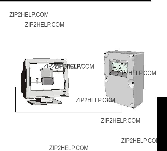
MultiRanger Communications
MultiRanger Communication Systems
The MultiRanger is an integrated level controller capable of communicating process information to a Supervisory Control and Data Acquisition (SCADA) system, via a serial device such as a radio modem, leased line, or
MultiRanger
Connection via radio modem,
The standard MultiRanger supports the following two communication protocols:
Modbus
Modbus is an industry standard protocol used by SCADA and HMI systems. The MultiRanger uses Modbus to communicate via the
Dolphin
Dolphin is a proprietary Siemens Milltronics protocol designed to be used with Dolphin Plus. For more information on Dolphin Plus or to obtain a copy of the software, please go to www.siemens.com/processautomation to contact your Siemens Milltronics representative.
Optional SmartLinx??Cards
The standard MultiRanger unit may also be enhanced with Siemens Milltronics SmartLinx?? communication modules that provide an interface to popular industrial communication systems.
This manual only describes the
Communications

Communications
Communication Systems
The MultiRanger is capable of communicating with most SCADA systems, PLCs, and PCs. The supported protocols are:
???Modbus RTU/ASCII ??? base unit on
???PROFIBUS DP ??? optional SmartLinx?? module
???
???DeviceNet?? ??? optional SmartLinx module
Communication Ports
The MultiRanger comes with two communication ports on the base unit.
The
???initial setup
???configuration
???troubleshooting
???periodic maintenance
The
???runs communications cable farther
???allows multiple slave units on the network, addressed by P771 ??? Network Address
To communicate with equipment requiring
Modbus
The Modbus protocol is supported in the base unit and can be configured using the Communications parameters P770 to P782.
To set up communications with a Modbus RTU master device on port 2 using
1.
DeviceNet is a registered trademark of Open DeviceNet Vendor Association.
SmartLinx
Other protocols are available through optional SmartLinx communications modules. Details on how to install and program these modules are contained in the SmartLinx documentation.
Dolphin Plus
Dolphin Plus software makes it easy to record and compare parameter sets for all the MultiRangers in your company. Dolphin Plus uses a proprietary protocol called Dolphin to communicate with Siemens Milltronics instruments. This protocol is set when P770 = 1.
By default the settings for port 1
Communications

Communications Installation
Wiring Guidelines
???the
???
???use 24 AWG (minimum)
???use good quality communication grade (shielded twisted pairs) cable that is recommended for
???run the communication cable separately from power and control cables (do not tie wrap your
???use shielded cable and connect to ground at one end only
???follow proper grounding guidelines for all devices on the bus
Note: Improper wiring and incorrect choice of cables are two of the most common causes of communication problems.
Ports 1 and 2
Port Wall Mount
1
2Connections for the
Ports 1 and 2:
The
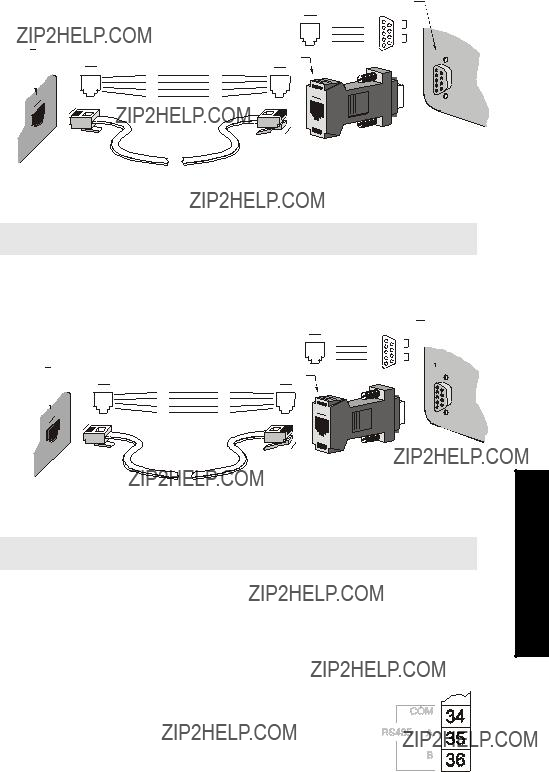
Port 1:
To connect the unit to a PC using an
Computer
Note: Jumper pins
To connect the unit to a modem using an
Note: Jumper pins
Port 2:
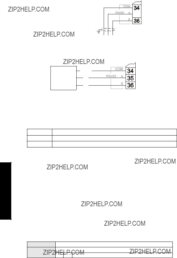
To connect the unit to an
MultiRanger
Terminal Block
Installation Comms
Comms Installation
MultiRanger
 Terminal Block
(Shield to be grounded at one end)
C A B
O
M
To connect the unit to a modem using an
B
Configuring Communication Ports (Parameters)
The 11 parameters listed are indexed to the two communication ports, unless otherwise noted: An asterisk (*) identifies the preset value.
1
2The
P770 Port Protocol
The communications protocol used between the MultiRanger and other devices.
The MultiRanger supports the Siemens Milltronics Dolphin format (www.siemens.com/ processautomation), and the internationally recognized Modbus standard in both ASCII and RTU formats. Other protocols are available with optional SmartLinx cards.
P771 Network Address
The unique identifier of the MultiRanger on the network.
Primary Index Communications Port ValuesRange: 0 to 9999
1 * Preset

For devices connected with the Siemens Milltronics protocol, this parameter is ignored. For devices connected with a serial Modbus slave protocol, this parameter is a number from
P772 Baud Rate
The communication rate with the master device.
This specifies the rate of communication in Kbaud. Any value may be entered, but the only values supported are those shown above. The baud rate should reflect the speed of the connected hardware and protocol used.
P773 Parity
The serial port parity.
Ensure that the communications parameters are identical between the MultiRanger and all connected devices, as many modems default to
P774 Data Bits
The number of data bits per character.
P775 Stop Bits
The number of bits between the data bits.
Installation Comms
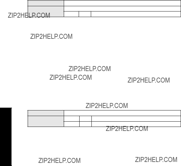
Comms Installation
P778 Modem Available
Sets the MultiRanger to use an external modem.
P779 Modem Inactivity Timeout
Sets the time that the unit will keep the modem connected with no activity.
To use this parameter, ensure that P778 (Modem Available) =1. Ensure that the value is low enough to avoid unnecessary delays when an unexpected disconnect occurs but long enough to avoid timeout while you are still legitimately connected. This parameter value is ignored by the Modbus Master Drivers as they automatically disconnect when done communicating.
Hanging Up
If the line is idle and the P779 Modem Inactivity Timeout expires, then the modem is directed to hang up the line. Ensure that P779 is set longer than the standard polling time of the connected master device. Set P779 to 0 to disable the inactivity timer.
P782 Parameter Index Location
Determines where index information is stored for the parameter access area for the Modbus register map.
For more on Parameter Index Location, see Parameter Access on page 102.

Modbus Register Map
Features affecting volume, mA input, and Average or Difference readings apply to the MultiRanger 200 only. They are clearly marked.
The memory map of the MultiRanger occupies the Modbus holding registers (R40,001 and up). This map is used when the protocol is Modbus RTU slave or Modbus ASCII slave.
Register Map for Most Common Data
Legend
1.Maximum registers shown; fewer may be used depending on options installed.
2.Varies according to model.
MR 100: Available as reading 1 and reading 2 when in either Single or Dual Point Mode. In Dual Point Mode, reading 1 and reading 2 are always available.
MR 200: Available as reading 1, reading 2, and Average or Difference when in either Single or Dual Point Mode. In Single Point Mode, point 2 and 3 are only available if P001 = Average or Difference. In Dual Point Mode, reading 1 and reading 2 are always available. Point 3 is only available if P001[3]= Average or Difference.
3.2nd volume available in Dual Point Mode only.
Types Register Modbus

Modbus Register Types
1.Maximum registers shown; fewer may be used depending on options installed.
The MultiRanger was designed to make it easy for master devices to get useful information via Modbus. This chart gives an overview of the different sections. A more detailed explanation of each section follows below.
Word Order (R40,062)
This determines the format of unsigned,
???0 indicates that the most significant word (MSW) is given first
???1 indicates that the least significant word (LSW) is given first
See Unsigned Double Precision Integer (UINT32) on page 107 for more information.
Note: Additional information is available from our Web site at www.siemens.com/
processautomation
Map ID (R40,063)
This value identifies the register map used by the MultiRanger. See P782 Parameter Index Location on page 96.
See also Parameter Access (R43,998 ??? R46,999) on page 102 for details.

Product ID (R40,064)
This value identifies the Siemens device type:
Point Data (R41,010 ??? R41,031)
Measurement point data contain the current instrument readings. These are the values shown for the reading measurement for each measurement point. The reading is based on the setting for P001 (operation). P001 can be set to level, distance, OCM flow, or volume. See Parameter Reference section on page 117 for details.
The measurement registers are 41,010 to 41,012. The MultiRanger uses 41,010 when configured with a single transducer and 41,010 to 41,012 when configured with two transducers (P111=4 or 5 only). Two transducers can create three readings because they can generate an average or differential reading (R41,012) as well as the two level readings (R41,010 and R41,011).
Available registers:
The reading is expressed as a percentage of full scale, multiplied by 100:
Totalizer (R41,040 ??? R41,043)
The totalizers are stored as 32 bit integers using two registers. The totalizers can be read with R41,040 and R41,041 as totalizer for Point 1, and R41,042 and R41,043 as totalizer for Point 2. The totalizer values can be reset to any value by writing that value to the registers. The values can be cleared by writing zero (0) to the registers.
Input/Output (R41,070 ??? R41,143)
The MultiRanger has discrete inputs, mA inputs, mA outputs and relay outputs. See below for details for each I/O type.
Types Register Modbus

Modbus Register Types
Discrete Inputs (R41,070)
This table shows the current status of the discrete inputs. Only register 41,070 is used.
Relay Outputs (R41,080)
This table shows the current status of the relays. A reading of 0 means that the relay function is not asserted and a 1 means that it is asserted. For example, a 1 for a pump relay means that the pump is running.
Values are written to control a relay only if the Relay Control Function (P111) is set to communications (65). See Relay Function Codes (P111 Only) on page 110.
mA Input (R41,090) [MR 200]
The mA input is scaled from 0 to 2,000 (0 to 20 mA multiplied by 100). P254 displays the value of the input. This parameter is indexed by the input number.
mA Output
The mA output is scaled from 0 to 2,000 (0 to 20 mA multiplied by 100). This is displayed in P911.
Pump Control (R41,400 ??? R41,474)
Only relays set for pump control (P111 = 50 to 52) are available. These registers have no effect on relays programmed for other uses.
Pump ON Setpoint (R41,420 ??? R41,425)
The ON setpoint level (P112) for the referenced pump relay.
The setpoint is scaled from 0 to 10,000 (0 to 100% of span multiplied by 100). So 54.02% is shown in the register as 5402.
Pump OFF Setpoint (R41,430 ??? R41,435)
The OFF setpoint level (P113) for the referenced pump relay.
The setpoint is scaled from 0 to 10,000 (0 to 100% of span multiplied by 100). So 54.02% is shown in the register as 5402.
Pumped Volume (R41,440 ??? R41,443) [MR 200]
The pumped volume registers hold the current total for all of the pumps associated with a level point. These registers are available only if operation is set to pumped volume (P001 = 7).
These volumes can become very large. Therefore, two registers are used to hold the value. See Unsigned Double Precision Integer (UINT32) on page 107 for more information.
The value in the registers is given as an integer value but must be interpreted as having the number of decimals set in P633 (LCD Totalized Decimal Position): this number can be 0 to 3. Ensure that your software accounts for these decimal places before you report the pumped volume totals.
Pump Hours (R41,450 ??? R41,461)
The number of running hours for the referenced pump relay. The hours are given to three decimal places, so the integer must be divided by 1000 to get the correct value. For example 12,340 represents 12.34 hours.
This value comes from parameter P310. See page 157 of the Parameter Reference section for details.
Pump Starts (R41,470 ??? R41,475)
The number of pump starts for the referenced pump relay.
This value comes from parameter P311. See page 157 of the Parameter Reference section for details.
Types Register Modbus

Modbus Register Types
Parameter Access (R43,998 ??? R46,999)
Parameter values are given as integers in the range of registers from R44,000 to R44,999. The last three numbers of the register correspond to the parameter number.
Usually, the parameters are all read / write.
Note:
???Parameters P000 and P999 are read only. If P000 is set to lock activated then all of the parameters are read only via the handheld programmer
???Parameter P999 (Master Reset) cannot be used via Modbus
???See Data Types on page 107 for a description of the different types of data associated with different parameters
Each parameter register has a corresponding format register that holds the format information required to interpret the value. See Format Words (R46,000 to R46,999) on page 105.
Parameter Indexing
Many parameters are indexed. There are two possible indexes: a primary index and a secondary index. A secondary index is a
The following is an example of a primary index:
P111 is the Relay Control Function. This parameter determines how a relay is controlled by the MultiRanger (used as an alarm, for pump control, etc.). Because there are up to six relays on the MultiRanger, P111 is indexed by six to allow each relay to be programmed independently.
A few parameters also have a secondary index. While a secondary index is important for setting up the MultiRanger, it is almost never needed through remote communications.
Indexing the Parameter Access Area
Each parameter communicates its value to only one register. You must know the index(es) for the parameter in order to interpret the information in the register correctly.
For example, to make use of the value returned in register R44,111 you must know which relay it is referring to. See Relay Function Codes (P111 Only) on page 110 for details on P111 values.
To determine the index values, the primary and secondary index must be read or write. The two possible methods of handling these index values are described in the following paragraphs: Global Index Method and Parameter Specific Index Method.

Reading Parameters
To read parameter values, follow the steps listed in either the Global or the Parameter Specific Index Method that follow. You must be able to program your HMI or SCADA system before completing these methods.
Global Index Method (P782 = 0)
Global format method sets index values for all parameters simultaneously. Use this method to read multiple values set to the same index values.
1.Write the primary index value into R43,999.
This is a value between 0 and 40 which specifies the input or output indexed by the parameter.
Examples are:
???Transducer 1 is index 1
???Discrete input 2 is index 2
???Relay 5 is index 5
2.Write the secondary index value into R43,998.
This is a value between 0 and 40 that specifies the secondary index on the parameter. This value is usually 0.
3.Write the desired format value into the appropriate format register. Because the primary and secondary indexes are already specified, these portions of the format word are ignored and only the last digit is significant.
See Format Registers on page 115 for details.
4.Read the value from the appropriate parameter register.
Types of values are:
???Numeric Values, on page 107
???Bit Values, on page 107
???Split Values, on page 108
???Text Messages, on page 109
???Relay Function Codes (P111 Only), on page 110
A value of 22,222 indicates that an error has occurred. Specify a different format type and try again.
Parameter Specific Index Method (P782 = 1)
The Parameter Specific index method sets the index values for each parameter independently. Use this method to read multiple parameters with different index values.
1.Write the primary index, secondary index, and data format values into the appropriate format register.
For example, to read the following information:
???measured level (P921)
???in units with three decimal places
Types Register Modbus

???from Transducer One
Send the integer value 01008 to register 46,921.
2.Read the value from the appropriate parameter register (the example uses 44,921). Types of values are:
???Numeric Values on page 107
???Bit Values on page 107
???Split Values on page 108
???Text Messages on page 109
???Relay Function Codes (P111 Only) on page 110
A value of 22,222 indicates that an error occurred. Specify a different format type and try again.
Writing Parameters
The method of writing parameters is similar to the method of reading them. Become familiar with Reading Parameters, page 103, before attempting to write any parameters.
To write parameter values to the MultiRanger, follow these steps:
Global Index Method (P782 = 0)
1.Write the primary index value into R43,999.
2.Write the secondary index value into R43,998.
3.Write the desired format value into the appropriate format register.
4.Write the value to the appropriate parameter register.
Parameter Specific Index Method (P782 = 1)
1.Write the primary index, secondary index, and data format values into the appropriate format register.
2.Write the value to the appropriate parameter register.
Modbus Register Types

Format Words (R46,000 to R46,999)
Format words are unsigned integers that contain up to three values (described below). The number of values used in the format words depends on the Parameter Index Location (P782) that is used.
Parameter P782 Parameter Index Location, described on page 96, determines which of two methods is used to access the format words: Global Index Method or Parameter Specific Index Method.
Global Index Method (P782 = 0)
Only the final digit of the format word determines the decimal offset (below).
All three decimal fields are used to determine the parameter value???s primary index, secondary index, and decimal offset.
Format Registers
Each format register is made up of three decimal fields:
???decimal offset
???secondary index
???primary index
decimal offset
secondary index
primary index
The primary and secondary indices correspond to those that are used by the parameter.
Types Register Modbus

The decimal offset indicates how the remote system must interpret the integer value that is stored in the parameter access register. The following table shows how different parameter values can be shown based on a register value (integer) of 1234.
Examples of using the format word for both the index values and the decimal offset value are shown below:
To write these values you can use a decimal offset as follows: format word = (primary index x 1000) + (secondary index x 10) + (decimal).
Modbus Register Types

Data Types
The MultiRanger parameters do not always use integers to hold values. For the convenience of the programmer, those values are converted to and from a
Numeric Values
Numeric parameter values are the most common. For example, parameter P920 (Reading) returns a number that represents the current reading (either level or volume, depending on the MultiRanger configuration).
Numeric values are requested or set in units or percent of span, and may be specified with a number of decimal places.
Numeric values must be in the range
If a parameter cannot be expressed in terms of percent of span, or has no meaningful value, the number 22,222 is returned. Try requesting the parameter in units, or refer to P005 in the Parameter Reference section on page 122.
Bit Values
Bits are packed into registers in groups of 16 bits (1 word). In this manual, the bits are numbered from 1 to 16, with bit 1 as the least significant bit (LSB) and bit 16 as the most significant bit (MSB).
Unsigned Double Precision Integer (UINT32)
Large numbers are put into unsigned 32 bit integers. By default, they are set up so that the first word (register) is the most significant word (MSW) and the second word (register) is the least significant word (LSW).
Types Data

Data Types
For example, if R41,442 is read as a UINT32, the 32 bits would look like this:
The two registers are read as a
The most significant word (MSW) and least significant word (LSW) can be reversed to accommodate some Modbus drivers. See Word Order (R40,062) on page 98 for details.
The position of the decimal place is dependent on the register. For more details see the description of the register.
Split Values
Certain parameters are actually a pair of numbers separated by a colon, using this format: xx:yy.
One example is P807, Transducer Noise, where:
xx= the average noise value in dB
yy= the peak noise in dB
The number which corresponds to xx:yy, either for reading or setting a parameter, is determined by the following formula:
For storing to the device:
value = (xx + 128) x 256 + (yy + 128) For reading from the device:
xx= (value / 256) ??? 128 yy = (value % 256) ??? 128
where % is the modulus operator.
The modulus can be computed by following these steps: value1 = value / 256
value2 = remainder of value1 value3 = value2 x 256
yy = value3 ??? 128
It may simplify Parameter to notice:
xx= (most significant byte of value) ??? 128
yy= (least significant byte of value) ??? 128

Text Messages
If a device parameter returns a text message, that message is converted to an integer and provided in the register. The numbers are shown in the following table:
Types Data

Data Types
Relay Function Codes (P111 Only)
Please note that the MultiRanger 200 offers more function codes.
If a device parameter returns a relay function code, that message is converted to a number and is then provided in the register. The numbers are shown in the following table:
MultiRanger 100
See P111 on page 134 of theParameter Reference section.
Error Handling
Modbus Responses
Error Handling
Errors can be traced to two general sources:
1.There is an error in transmission.
OR
2.The host tries to do something that is not a valid action.
In the first case, the MultiRanger does not respond and the master waits for a response time out error, which causes the master to
In the second case, the response depends on what the host tries to do. In general, MultiRanger will not give an error to the host request. Various actions and the expected outcome are as follows:
???If the host reads an invalid register, the host will get an undetermined value back.
???If the host writes an invalid register (a
???If the host writes a read only register, then the value will be ignored and no error response will be made. However, the current value will not reflect the desired new value.
???If P000 is activated, then the value will be ignored and no error response will be made. However, the current value will not reflect the desired new value.

???If the host attempts to write one or more registers that are out of range, an exception response code 2 or 3 is generated, depending if the start address is valid.
???If the host used an unsupported function code, an exception response code of 01 should be generated. However, this is not guaranteed and there may be no response.
Error Handling

Communication Troubleshooting
Generally
1.Check the following:
???There is power at the unit
???The LCD is showing the relevant data
???The device can be programmed using the hand programmer
2.Check the wiring pin outs and verify that the connection is correct.
3.Verify that values in the
4.Check that the port on the computer is correct. Sometimes trying a different Modbus driver will solve the problem. An easy
??? Some parameters can only be changed when the device is not scanning. Try putting the device in program mode, using the operating mode function.
??? Try setting the parameter from the keypad. If it can not be set using the keypad, check the lock parameter and set it to 1954.

Communication Appendix A
Communication Appendix A: Single
Parameter Access (SPA)
This Appendix is intended to provide someone with advanced communications knowledge the ability to access any parameter value in any available format.
Built into MultiRanger is an advanced handshaking area that can be used to read and write single registers to the MultiRanger. This section performs a similar function to the Parameter access section. The differences are:
1.Advanced section is more powerful and harder to program.
2.Advanced section only gives you access to one parameter at a time.
Mapping
Parameter Read and Write (40,090 ??? 40,097) is a series of eight registers used for reading and writing parameter values to and from the MultiRanger. The first three registers are always unsigned integers representing parameters and index values. The second five registers are the format and value(s) of the parameter.
All parameters normally accessed through the
Reading Parameters
To read parameters through Modbus do the following steps:
1.Send the parameter, its primary index, and its secondary index (usually 0), and format to registers 40,090 to 40,093.
2.Wait until you can read the written values from the registers (40,090 to 40,093) to confirm that the operation is complete.
3.Read the value from registers 40,094 and 40,095.

Writing Parameters
To set parameters through Modbus do the following steps:
1.Send the parameter, its primary index, and its secondary index (usually 0) to registers 40,090, 40,091, and 40,092.
2.Write the value to registers 40,096 and 40,097.
3.Write the desired format word to register 40,093 to enable the MultiRanger to interpret the value correctly.
Format Register
For example, to format the level reading so that it is shown in percent with two decimal places shifted left, the format bits would look like this:
The value sent to the MultiRanger is 0001001000000000 binary or 512 decimal. The value 512 is sent as an integer to register 40,093 to format the output words 40,094 and 40,095 accordingly.
If the numeric data type is set for integer and the value contains decimal places, they are ignored. In this situation, use the decimal offset to ensure that you have an integer value and then write your code to recognize and handle the decimal offset.
A Appendix Communication

Error Codes
The error codes returned in the format area are
Currently the MultiRanger has two error codes available.
Values Description
0No error
Communication Appendix A

Parameter Reference
The MultiRanger is configured through its parameters, and the application determines the parameter values which are entered into the unit.
Please check your value entries carefully before operating the MultiRanger to ensure optimum performance.
MultiRanger 100 and MultiRanger 200
All MultiRanger 100 and MultiRanger 200 parameters are listed in this section. MultiRanger 200 parameters are identified separately. The parameter title includes this marking [MR 200], indicating that parameter applies to the MultiRanger 200 only.
As a general rule, parameters affecting volume apply only to the MultiRanger 200.
Helpful Hints
Please note the following:
???Default values are always indicated with an asterix (*)
???Global values are common for all inputs and outputs on the unit
???Indexed parameters can apply to more than one input or output
???Primary index relates to an input or output
???Secondary index allows for multiple values on an indexed point
Accessing a Secondary Index
1.Press MODE  , and then press DISPLAY
  to activate secondary index. The
  icon appears under the index field.
2.Enter the secondary index, and then enter the values to set the secondary index.
Parameters

Index types
1.MultiRanger 100: The two level points are: Transducer One and Trans- ducer Two.
Level point typically has 1 index in Single Point Mode (standard), and 2 indexes in Dual Point Mode (optional).
MultiRanger 200: The three level points are: transducer 1, transducer 2, and the calculated point which can be difference (P001=4) or average (P001=5).
Level point typically has 1 index in Single Point Mode (standard), and 2 indexes in Dual Point Mode (optional). A third index is available in both modes when Operation (P001) is set for DPD (P001=4) or DPA (P001=5).
2.MultiRanger 200: The number of indexes available in Single Point Mode (standard) is typically 1, but can be expanded to 2 if Operation (P001) is set for DPD (P001=4) or DPA (P001=5).
In Dual Point Mode (optional), the number of available indexes is always 2.
Parameters

P000 Lock
Notes:
???This lock only applies to the handheld programmer: it does not lock access through communications.
???A remote master can change configuration if P799 is set to allow this.
Secures the MultiRanger from changes via the handheld programmer.
WARNING:
Use this lock as backup security only. It uses a fixed value which can be discovered by unauthorized personnel.
Access this parameter directly (type 000) and enter any value (except 1954) to secure programming lock. To unlock the MultiRanger, access this parameter and enter 1954.
Quick Start (P001 to P007)
P001 Operation
Sets the type of measurement required for the application.
Parameters

For DPD and DPA Programming [MR 200]
Please note that this feature is only available on the MultiRanger 200.
Single Point Model Use
For Dual Point Difference (DPD) or Dual Point Average (DPA), the unit requires either two transducers of the same type, or one transducer and one mA input. If two transducers are used, all transducer parameters become indexed, and a third level point is calculated.
???DPD (difference) = Point 1 - Point 2
???DPA (average) = (Point 1 + Point 2) / 2. The calculated DPD or DPA is always based
on level measurements of points 1 and 2.
For these operations any of three level points (transducer 1, transducer 2, or the calculated point) can be used to trigger relays (see P110 Level Source on page 134).
The points must be globally set to either 4 or 5 (as required). Point 3 becomes the calculated value as shown above. See Rake Control example on page 69.
Dual Point Model Use
To set a dual point MultiRanger for DPA or DPD functions, Point 3 must be set to either 4 or 5 (as required). Points 1 and 2 cannot be set to 4 or 5, but these points are used to calculate the value in point 3.
This table shows the available functions:
P002 Material
Specifies material type.
Parameters
P003 Maximum Process Speed
Determines level change reaction.
Use a setting just fast enough to keep up with your process. Slower settings provide higher accuracy. Faster settings allow for more level fluctuations.
P004 Transducer
Specifies the Siemens Milltronics transducer connected to the unit.
(chart con???t next page)
Parameters

Related
(chart cont???d from previous page)
???P203 mA Output Value/Transducer
???mA Input (P250 to P260) (related only to Value 250)
???P800 Near Blanking
???P823 Reform Echo
???P832 TVT Shaper Adjust
???P840 Short Shot Number
???P841 Long Shot Number
???P842 Short Shot Frequency
???P843 Long Shot Frequency
???P844 Short Shot Width
???P845 Long Shot Width
???P852 Short Shot Range
Parameters
P005 Units
Specifies measurement units used for dimensional values.
Changing this value automatically changes the units displayed for many parameters. Existing values are converted and do not have to be
P006 Empty
Enter distance in units (P005) from the face of the transducer to the process empty point.
Setting this value also sets Span (P007) unless Span was already set to another value. For distance operation (P001=3), Span is preset to Empty.

P007 Span
Sets the range levels to be measured.
Span is preset for a value close to the maximum available. Enter a value reflecting maximum application range.
Always prevent the monitored surface from approaching within 0.3 m (1 ft) of the transducer face as this is the minimum blanking for most Siemens Milltronics transducers (some require more blanking ??? see your transducer manual).
Many other parameters are set as a percentage of span (even if they are entered in units). The values of these other parameters may change if the span is altered after installation and the other parameters are measured using a level determined upward from the Empty level toward the transducer face.
MultiRanger 200
All volumes are based on span so it should be set for the maximum volume point if volume calculations are needed.
Volume (P050 to P055) [MR 200]
Please note that the volume parameters apply only to the MultiRanger 200.
Use these parameters to enable the MultiRanger to show readings based on vessel or wet well volume (rather than level)..
Parameters
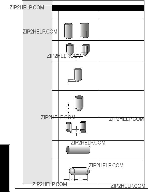
P050 Tank Shape [MR 200]
Enter the Tank Shape value matching the monitored vessel or wet well.
When Operation is LEVEL (P001 = 1), liquid (material) volume is calculated.
Alternatively, when Operation is SPACE (P001 = 2), remaining vessel capacity is calculated. In RUN mode, readings are displayed in percent of maximum volume. To convert readings to volumetric units, see Maximum Volume (P051).
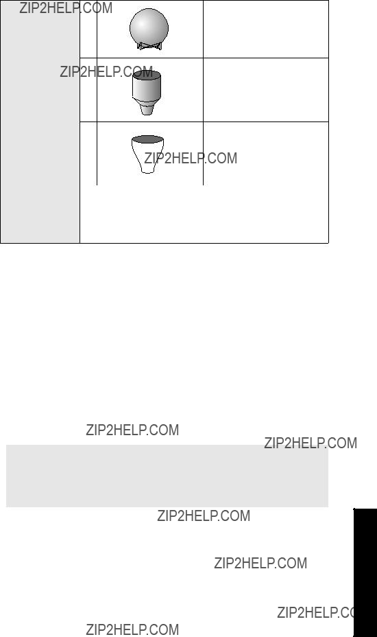
P051 Maximum Volume [MR 200]
For Readings in volumetric units (rather than percent), enter the equivalent vessel volume for Span (P007).
Any volume units can be chosen because volume is calculated from empty to maximum span and is scaled according to the Tank Shape (P050) value.
Note: Make sure selected chosen units allow LCD volume display.
Examples:
???If max. volume = 3650 m3, enter 3650
???If max. volume = 267500 gallons, enter 267.5 (thousands of gallons)
Parameters

Parameters
P052 Tank Dimension A [MR 200]
Dimension A as used in P050 Tank Shape.
Enter one of the following:
???height of the tank bottom if P050 = 2,3,4, or 5
OR
???length of one end section of the tank if P050 = 7, in Units (P005)
P053 Tank Dimension L [MR 200]
Dimension L as used in P050 Tank Shape.
Enter the following:
???tank length (excluding both end sections) if P050 = 7
P054 Level Breakpoints (Universal Volume Calculation)
[MR 200]
When the tank shape is too complex for any of the preconfigured shapes, you can specify the volume based on segments.See ???Accessing a Secondary Index??? on page 117 for more information.
Enter the following:
???up to 32 level breakpoints (where volume is known) if P050 = 9 or 10
Entering a Level Breakpoint
1.Go to Parameter P054.
2.For each index enter a breakpoint in measurement units.
3.Ensure that each breakpoint corresponds to the same index for P055.

P055 Volume Breakpoints and Characterization
(Universal Volume Calculation) [MR 200]
Each segment defined by the level breakpoints (P055) requires a volume so that the MultiRanger can make the
Typical volume calculations
ConeCylinder
Entering a Volume Breakpoint
1.Go to Parameter P055.
2.For each index enter a volume.
3.Ensure that each volume corresponds to the same index for P054.
For more on Volume Characterization, go to page 52.
Display and Reading (P060 to P062)
These parameters are used to:
???Change the number of decimal places displayed
???Convert the Reading to alternate units
???Reference measurements to other than Empty (P006) or Span (P007)
P060 Decimal Position
Defines the maximum number of decimal places used on the LCD.

Parameters
In RUN mode, the decimal position adjusts to prevent the number of digits from exceeding the display capabilities. To keep the decimal place from shifting, reduce the number of decimal places to that shown at 100%.
Example:
If 100% is 15m, use two decimal places for sample readings of 15.00 or 12.15.
P061 Convert Reading [MR 200]
Multiplies the current value by the specified amount to allow for scaling.
Examples:
???If the measured value is in feet, enter 0.3333 to display the number of yards
???For simple linear, volume conversions set POO5 to 1 (meters) and then enter the volume measurement per unit to get the correct conversion. For example, if the reservoir contains 100 litres per vertical meter, use 100 to get the reading in litres.
Notes:
???This method does not calculate volume. It must not be used in place of the volume parameters if any volume dependent features (such as pump efficiency) are used. To calculate true volumes see Volume (P050 to P055).
???Avoid entering a value that, when multiplied by the maximum current Reading, exceeds the display capabilities. If value exceeds four digits, EEEE is shown.
P062 Offset Reading
Adds the specified value to the level reading, usually to reference the reading to sea level or another datum level.
The operation of the device is not affected by the Offset Reading. This value is used for display purposes only. All control measurements are still referenced to Empty.

Backup Level Override
Use this feature to override the ultrasonic reading by a discrete input such as a contacting point device. The ultrasonic reading will be fixed at the programmed switch level until the discrete input is released.
The ultrasonic device makes decisions based on the override values.
P064 Reading Override Enable
Sets the discrete input to act as the source for a level reading override.
P065 Reading Override Value
This value is substituted for the current reading when the selected discrete input is enabled and activated.
Parameters

Parameters
Please note the following:
???enter value in current units (as selected in P005)
???valid for level, space, and distance
???volume is calculated based on the Backup level
Example:
Transducer One is configured for a level measurement. Digital Input 2 is connected to a Hi Level Backup switch located a level of 4.3m.
When the level rises to 4.3m, and the switch is activated, the reading is forced to 4.3m. The reading stays at 4.3m until the switch is
P066 Override Time Delay
Defines the time used to calm (debounce) the override condition input. Set in seconds.
Note: Activation of the Level Override is subject to the measurement cycle. This can add up to four seconds to the overall response time depending on operating conditions and programming.
P069 Password
Holds the current password for P000.Select by typing in 069.You cannot scroll to this parameter.
This parameter is
Failsafe (P070 to P072)
P070 Failsafe Timer
The time for invalid measurements to elapse before Failsafe State activates.
Once activated, the Failsafe State initiates the following:
1.The material level is reported based on P071 Failsafe Material Level.
???The unit responds to the new level as programmed (control and alarm relays activate as defined by the programming).
???Individual relays can have independent failsafe responses. See P129 Relay Failsafe.
2.The appropriate error is displayed:
???LOE for loss of echo from the transducer
???Short for a shorted transducer cable
???Open for a cut transducer cable
???Error for all other problems
When modifying the preset value, set it short enough to protect the process but long enough to avoid false alarms. Only use No Delay (0.0 Minutes) for testing.
P071 Failsafe Material Level
The material level reported when a Failsafe State is initiated.
Select the Failsafe Material Level based upon the relay operation required during failsafe operation.
Parameters

Parameters
Selecting HI, LO, or HOLd
1.Press FUNCTION 


 to display the Auxiliary Function symbol.
2.Press ARROWS 


 to scroll to the desired option.
3.Press ENTER 
 to set the value.
Entering a Measurement
To enter a specific Failsafe Material Level within
Relay reaction
The way in which relay programming reacts to the failsafe level depends on P129 Relay Failsafe (page 140). By default:
???Alarm relays have P129 = OFF and so react to the Failsafe Material Level.
???Control relays have P129 = dE and so
P072 Failsafe Level Advance
Sets the speed the MultiRanger advances to and returns from the Failsafe Material Level.
Relays (P100 to P119)
The MultiRanger has three or six relays (or digital outputs) used to control devices and alarms. While the number of devices is limited by the relays, all control functions are accessible through software and each parameter is indexed to the three or six relays. See the Relay section on page 41.
Preset Applications (P100)
The MultiRanger makes standard applications easier to program by providing an extensive list of presets.

Control Functions (P111)
Each relay can be configured independently to take advantage of the MultiRanger???s advanced features and flexibility. Start with a preset application and then change the required parameters to make the task more efficient.
Setpoints (P112, P113)
Each relay is triggered by one or more setpoints. The setpoints can be based on absolute level (P112, P113) or rate of change (P702, P703). Each control function specifies which setpoints are required.
P100 Preset Applications [MR 200]
Six preset applications to configure or bench test the unit.
Select an application that is similar to yours and change the parameters required. If none suit, then refer to P111 Relay Control Function on page 134.
Note: Programming the relays independently is the most common method used.
Parameters

P110 Level Source
Sets the level source on which the indexed relay is assigned to a measurement point.
Please note that Difference and Average settings are MultiRanger 200 features.
MultiRanger 200
Please note that these features are only available on the MultiRanger 200.
In Single Point Mode (standard):
Points 2 and 3 are available only if Operation is set for difference or average (P001 = 4 or 5).
In Dual Point Mode (optional):
Point 2 is always available, and Point 3 is available only if Operation is set for difference or average (P001 = 4 or 5).
P111 Relay Control Function
Sets the control algorithm used to trip the relay.
Please note that parameter P111 values vary between the MultiRanger 100 and the MultiRanger 200.
Use zero 0 (preset) to disable control of the indexed relay.
Note: All relay ON/OFF points must be referenced from Empty (P006), regardless of Operation Mode selection (POO1).
Parameters

MultiRanger 100
Values For P111
1.When reading and setting this parameter through Modbus or SmartLinx communications the parameter values are mapped to different numbers.
See MultiRanger Communications on page 89 for Modbus information or the relevant SmartLinx??manual.
MultiRanger 200
Values For P111
Parameters

Values For P111
1.When reading and setting this parameter through Modbus or SmartLinx communications the parameter values are mapped to different numbers.
See the MultiRanger Communications section on page 89 for Modbus information or the relevant SmartLinx?? manual.
P112 Relay ON Setpoint
Sets the process point at which the relay changes from its NORMAL state.
For most applications, the relay is tripped at this point. For
Parameters

P113 Relay OFF Setpoint
Sets the process point at which the relay returns to its NORMAL state.
For most applications, the relay is reset at this point. For
P115 Relay Interval Setpoint [MR 200]
The length of time in hours between starts.
P116 Dead Band [MR 200]
The distance above and below the bound alarm setpoints.
Parameters

For
Enter the dead band in either percent of span or units of measure (P005). The dead band value is applied both above and below the upper and lower bound setpoints as shown in the fig- ure.
Actual ON or OFF setpoint
P116
 Setpoint set in P112 or P113 P116
Actual OFF or ON setpoint
Parameters
P118 Relay Output Logic
The logic applied to relays to determine the contact open or closed state.
The relay contact operation is NORMALLY CLOSED for alarms and NORMALLY OPEN for controls. See P111 Relay Control Function for more information.
Note: P118 is not reset by a master reset (P999).
Power Failure
When power is cut to the MultiRanger, its relays fail to the following states:
1.Relays 3 and 6 are Form C types, so you can wire it either NORMALLY OPEN or NORMALLY CLOSED. Check the wiring before programming.
To use relays 3 or 6 as general alarm indicators, set P118 to 3 ??? negative logic and wire the alarm for normally open operation. When an alarm event occurs (see below) or when power is cut, the circuit closes and the alarm activates.

Positive Logic
In software, all relays are programmed the same way, with ON setpoints indicating when to change the relay contact state (open or closed). This parameter allows the reversal of the operation so that relay contacts can be NORMALLY CLOSED or NORMALLY OPEN.
P118 is preset to 2 which is positive logic.
Negative Logic
When P118 = 3 (negative logic), the operation for the indexed relay is reversed from normal.
P119 Relay Logic Test
Forces the relay control logic into an ACTIVATED or
This parameter tests site wiring and control logic programming. Forcing the relay to an activated or
Pump Setpoint Modifiers (P121 and P122) [MR 200]
Please note that these parameters apply to the MultiRanger 200 only.
These parameters provide alternate ways of starting the pumps in the pump group. See the Pump Control section on page 58 for descriptions of the pump control algorithms.
P121 Pump by Rate [MR 200]
Sets the pump relays to accept control by rate of level change once the first ON setpoint is reached.
Use this function when multiple pumps are to be controlled by rate of level change rather than by setpoints.
Parameters

Parameters
The delay between pump starts is set by P132 Pump Start Delay.
This only applies to any relays set to pump control (P111 = 50 to 56).
Notes:
???All pump control relay ON and OFF setpoints must be the same value
???If the level is within 5% of Span (P007) of the OFF setpoint, the next pump is not started
P122 Pump Service Ratio [MR 200]
Selects pump usage based on the RUN time ratio rather than last used.
This parameter only relates to relays with P111 = 54 or 55.
To make this parameter useful, assign it to all of the pump relays. The number assigned to each pump relay represents the ratio applied to decide the next pump to start or stop.
Notes:
???The MultiRanger will not sacrifice other pumping strategies to ensure that the ratio is held true
???If the pump relays are set to the same value then the ratio equals 1:1 and all pumps are used equally (preset)
Independent Relay Failsafe (P129)
P129 Relay Failsafe
Sets how individual relays react to a failsafe condition, to allow for more flexible programming.
Use this for operations independent of the Failsafe Material Level (P071).
Relay Failsafe is only available for the following relay functions (P111) and is not used for any other relay control function.
To select an independent Relay Failsafe value:
1.Press FUNCTION 

 to display the Auxiliary Function symbol.
2.Press ARROWS 


 to scroll through the failsafe options.
3.Select option and press ENTER 
 .
.
Advanced Pump Control Modifiers (P130 to P137) [MR 200]
Please note that these parameters apply to the MultiRanger 200 only.
These parameters only affect relays set to pump operation (P111 = 50 to 56).
P130 Pump
Sets the number of hours between pump
To clear sediment in a
Parameters

Parameters
P131 Pump
Sets the number of seconds that the pump runs on.
Your pump capacity determines the amount of material that can be removed. Choose a value long enough to clean out the vessel bottom, yet short enough not to run the pump dry. Also be sure that this value does not overlap with P130 (Interval). The timing should look something like this:
P132 Pump Start Delay [MR 200]
Sets the minimum delay (in seconds) between pump starts.
Use this feature to reduce a power surge from all pumps starting at the same time. This delay determines when the next pump is permitted to start.
P133 Pump Power Resumption Delay [MR 200]
Sets the minimum delay before the first pump restarts after power failure.
This reduces the surge from the first pump starting immediately on power resumption. When this delay expires, other pumps will start as per P132.

P136 Wall Cling Reduction [MR 200]
Varies the upper and lower setpoints to reduce material buildup on the walls.
This value is the range in which the setpoints are allowed to deviate in percent or units. The Relay Setpoints ON and OFF values are randomly varied inside the range to ensure that the material level does not consistently stop at the same point.
P137 Pump Group [MR 200]
Puts pumps into groups for multiple pump rotations on one transducer.
This feature groups pumps (relay points 1 - 6) into groups 1 or 2. It is applied to pump rotation and occurs independently within each group.
Parameters


P171 Flush Cycles [MR 200]
Sets the number of pump cycles requiring flush control.
If three flush cycles are required after every ten pump cycles then:
P172 (Flush Interval) = 10
P171 (Flush Cycles) = 3
P172 Flush Interval [MR 200]
Sets the number of pump cycles before flush control is enabled.
To start a new flush cycle every ten times the pumps are run, set this to 10.
P173 Flush Duration [MR 200]
The length of time for each flush cycle that the flush control is active.
Parameters
mA Output (P200 to P219)
P200 mA Output Range
Determines the mA output range.
If either 1 or 2 is selected, the mA output is directly proportional to the mA Function. If either 3 or 4 is selected, then the output is inversely proportional. After setting P200, verify that P212 has a valid entry for mA Output Min Limit, as P212 is not changed automatically by a change to P200.
P201 mA Output Function
Alters the mA output/measurement relationship.
Please note that parameter P201 values vary between the MultiRanger 100 and the MultiRanger 200.
MultiRanger 100
MultiRanger 200
P202 mA Output Allocation
Sets the input source from which the mA output is calculated.
Please note that parameter P202 values vary between the MultiRanger 100 and the MultiRanger 200.
MultiRanger 100
MultiRanger 200

Enter the Point Number the mA output is based on. This value depends on whether mA function (P201) is set as transducer or mA input.
For a single point device, if P201 uses a transducer, parameter P202 can only be altered if P001 (Operation) is set for DPD or DPA.
P202 can be set to a particular point or range of points. When set to a range of points, the mA output will be the average of the readings from all in service transducers in the range. Out of service transducers will be ignored.
If P202 mA Output Allocation End contains the value 0, then only 1 transducer has been assigned to the mA output.
P203 mA Output Value / Transducer
Displays current mA output value for the Point Number.
This displays as an Auxiliary Reading when  key is pressed in the RUN mode and does not include adjustments made using Trim features (P214 / P215).
P203 holds the mA value associated with a transducer. This value is used for run mode display of the mA output. When only one mA output is associated with a transducer, this parameter holds the value of that mA output. When more than one transducer is associated with a mA output (set via P202), P203 holds the mA output calculated from the resulting average of the associated transducer readings. When more than one mA output is associated with a transducer, P203 holds the value of the first mA output associated
with the transducer.
Note: This parameter is applicable only if any mA output has the transducer
Point Number as its input source (see P201 and P202).
Parameters


P250 mA Input Range [MR 200]
Shows the mA input range of the connected mA device.
10 to 20 mA
Values
2* 4 to 20 mA
Ensure this range corresponds to the output range of the external device. All level measurements will equate % of Span with the % of the mA range.
P251 0 or 4 mA Input Level [MR 200]
Shows the process level corresponding to the 0 or 4 mA value.
When using an external mA signal to determine level, the input range must be scaled to give accurate results.
P252 20 mA Input Level [MR 200]
Shows the process level corresponding to the 20 mA value.
Input range is scaled for accuracy if an external mA signal calculates level.
Parameters

P253 Input Filter Time Constant [MR 200]
Shows the time constant used in the mA input filter to dampen signal fluctuations.
Range: 0 to 9999
Values
Preset: 1
This number in seconds is used in the damping calculations. Larger values damp more than smaller values and 0 disables the signal filter.
P254 Scaled mA Input Value [MR 200]
Shows the resulting level value after scaling.
Range:
Values
Preset: calculated from the input mA signal
This parameter is calculated from the input mA signal.
P260 mA Raw Input [MR 200]
Shows the raw mA input supplied by the external device.
Discrete Input Functions (P270 to P275)
Discrete inputs can be used for the following:
???Passing other information to a remote system through communications
???Backup level override
Use the parameters listed above to have discrete inputs modify the unit???s operation. Use the following parameters to configure the discrete input itself.
See also the Pump Control section on page 58 for a description of the MultiRanger???s pump control algorithms, including how the discrete inputs alter its operation.
Parameters


P300 Temperature, Transducer Maximum
Shows the highest temperature encountered, as measured by the temperature sensor in the transducer (if applicable).
P301 Temperature, Transducer Minimum
View the lowest temperature encountered, as measured by the temperature sensor in the transducer (if applicable).
P302 Temperature, Sensor Maximum
View the highest temperature encountered, as measured by the
Parameters


P309 Pump RUN Time
Displays the amount of time in minutes since a relay was last activated.
Parameter measures the length of time since a relay was asserted, most often to determine how long a pump has been running. Alternatively, it can monitor a relay to show how long it has been in a state of alarm. It resets every time the relay is activated.
P310 Pump Hours
View or reset the accumulate ON time for the displayed Relay Number.
Value is displayed with a floating decimal point (the more figures displayed before the decimal, the fewer displayed after). It is the value displayed when  key is pressed in the RUN mode.
P311 Pump Starts
View or reset the accumulated number of times the Relay Number has been ON.
This value is displayed when  key is pressed and held for five seconds in RUN mode.
P312 Pump Run Ons [MR 200]
View or reset the accumulated number of times the displayed Relay Number has been held ON via Run On Interval (P130).
Please note that this parameter applies to the MultiRanger 200 only.


P331 Auto Record Enable
Use to enable/disable the Auto Profile Record function.
P332 Auto Record Transducer
Specifies the Transducer Point Number for which Auto Profile Records are saved.
Please note that Differential and Average operation is a MultiRanger 200 feature.
MultiRanger 200
This feature is preset to Point Number 1. (Alteration is only required if differential or average Operation [P001 = 4 or 5] is selected.)
P333 Auto Record Interval
Enter the time to elapse after an Auto Profile Record is saved before another Auto Profile Record can be saved (subject to all other restrictions).
Range: 0.0 to 166.6 (minutes)
Values
Preset: 120
Parameters

Auto Record ON and OFF Setpoints (P334 to P337)
Use Auto Record ON Setpoint (P334) and Auto Record OFF Setpoint (P335) to define the boundaries within which the level must be, for the resultant Echo Profile to be considered for an Auto Profile Record.
If
Enter the level value in Units (P005) or percent of Span (P007) as referenced to Empty (P006).
P334 Auto Record ON Setpoint
Enter the critical level which, in conjunction with Auto Record OFF Setpoint, defines the boundaries for Auto Profile Records to be saved.
P335 Auto Record OFF Setpoint
Enter the critical level which, in conjunction with Auto Record ON Setpoint, defines the boundaries for Auto Profile Records to be saved.
Parameters

P336 Auto Record Filling / Emptying
Use this feature to restrict Auto Profile Records from being saved unless the level is rising, falling or either.
If the level changes at a rate in excess of the corresponding Filling / Emptying Indicator (P702 / P703) values, the Echo Profile is saved subject to this and other Auto Profile Record restrictions.
P337 Auto Record LOE Time
Limits Auto Profile Records from being saved unless extended LOE occurs.
If the LOE condition exceeds the period entered, the Echo Profile is saved. When set for 0 LOE is not required for an Auto Profile Record to be saved.
Parameters

Installation Records (P340 to P342)
P340 Date of Manufacture
View the date of manufacture of this MultiRanger unit.
P341 RUN Time
View the number of days this MultiRanger has been in operation.
The RUN Time value is updated once a day, and cannot be reset. However, in the event of a power interruption, the counter won???t advance. Therefore, a unit that is powered down on a regular basis will not have an accurate value.
P342 Start Ups
The number of times power has been applied since the Date Of Manufacture.
Parameters

Open Channel Monitoring (P600 to P621) [MR 200]
Open Channel Monitoring (OCM) operation is a MultiRanger 200 feature only.
If the MultiRanger is used to monitor open channel flow, alter the following parameters as required and run a calibration as described in P621.
Note: See Open Channel Monitoring (OCM) on page 73 for application examples involving common weirs and flumes.
The MultiRanger measures head as referenced to Empty (P006) or OCM Zero Offset (P605), when Operation is set for OCM (P001 = 6). Flowrate, based on head (at the point of measure specified by the Primary Measuring Device fabricator) is also calculated and displayed on the LCD.
Some Primary Measuring Devices require a longer Range Extension (P801) to avoid entering the LOE failure state if the water level falls below the zero point of the Primary Measuring Device. See P801 Range Extension on page 200 for more information.
P600 Primary Measuring Device [MR 200]
The type of primary measuring device (PMD) used.

The MultiRanger is
Associated parameters Max Head (P603), Max Flow (P604), and Min Head (P605) may be scroll accessed. If Operation is not set for OCM (P001 = 6), this value is preset to 0. If Operation is set for OCM, it is preset to 1.
P601 Flow Exponent [MR 200]
The Exponent for the flow calculation formula.
Use this parameter if the Primary Measuring Device (P600) is set to 1 (exponential). It creates an exponential curve with end points set by Max Head (P603) and Zero Head (P604) and with the curve based on the specified exponent.
If P601 = 1, the flow characteristic is a straight line
Use the exponent specified by the PMD manufacturer, if available, or the sample value given below.
Parameters


Example
P605 Zero Head [MR 200]
The distance above Empty (P006) in Units (P005) representing zero head (and zero flow).
This feature can be used for most weirs and some flumes (e.g. Palmer Bowlus) where the zero reference is at a higher elevation than the channel bottom.
Transducer
Material level at zero flow
Zero Head (P605)
Parameters

P606 Time Units [MR 200]
Determines the units used to display current flow and logging flow values.
This is used when the Primary Measuring Device is Ratiometric (P608=0).
Example
P607 Flowrate Decimal [MR 200]
The maximum number of decimalplaces to be displayed.
In RUN mode, the number of decimal places displayed is automatically adjusted (if necessary) to prevent the number of Flowrate digits from exceeding display capabilities.
The maximum number of head decimal places is controlled by Decimal Position (P060).
Parameters
P608 Flowrate Units [MR 200]
The volume units used to display total flow.
Note: Set this parameter only when using
This parameter is enabled only if the primary measuring device (PMD) supports absolute calculations (P600=6,7). For absolute PMDs (P600=6,7) volume units can be specified using this parameter. If needed, absolute PMDs can still use ratiometric (P608=0) to accommodate other units.
Parameters


Pumped Volume Totalizer (P622) [MR 200]
The Pumped Volume Totalizer is a MultiRanger 200 feature only.
If the
P622 Inflow / Discharge Adjust [MR 200]
The method used to calculate the volume pumped, for pumped total Operation (P001 = 7).
* or discharge
Parameters

Totalizer (P630 to P645) [MR 200]
The Totalizer features apply to MultiRanger 200 only.
P630 LCD Totalized Multiplier [MR 200]
Use this feature if the LCD Total increments by too large (or too small) an amount.
Enter the factor (powers of 10 only) by which actual volume is divided, prior to display on the LCD. Use a value such that the
Example:
For an LCD Total display in 1000s of volume units, enter 3.
Parameters

Enter the factor (powers of 10 only) by which actual volume is divided, prior to Remote Totalizer count increment.
Example:
For a Remote Totalizer update by 1000s of volume units, enter 3.
P641 Flow Sampler Mantissa [MR 200]
Use this feature in conjunction with Flow Sampler Exponent (P642) to establish the number of flow units required to increment the Flow Sampler (device connected to the MultiRanger relay set for the flow sampler operation Relay Function, P111 = 41).
This parameter is relevant only if Operation is set to OCM (P001 = 6).
Enter the mantissa (Y) for the exponent (Z) in the formula:
Flow Sampler Increment = Y x 10Z Flow units.
Example: To count once every 4310 (4.31 x 10³) flow units:
???set P641 to 4.31 and P642 to 3
P642 Flow Sampler Exponent [MR 200]
Use this feature in conjunction with Flow Sampler Mantissa (P641) to establish the number of flow units required to increment the Flow Sampler (device connected to the MultiRanger relay set for the flow sampler operation Relay Function, P111 = 41).

This parameter is relevant only if Operation is set to OCM (P001 = 6).
Enter the exponent (Z) for the mantissa (Y) in the formula:
Flow Sampler Increment = Y x 10Z Flow units.
P645 Relay Duration [MR 200]
Use this feature (if desired) to adjust the minimum contact closure duration of a relay set as a totalizer, flow sampler, time (control), or aeration (P111 = 40, 41, 60 or 62)
Enter minimum contact closure duration (in seconds) required by the device connected.
For the flow sampler function this value is used for both the ON time of the relay and the OFF time between contacts.
relay contact closed
relay contact open
Range Calibration (P650 to P654)
There are two types of calibration possible:
Offset: Adjusts the measurements by a fixed amount.
Sound Velocity: Adjusts speed of sound and changes the measurement calculations.
Do Offset calibration at any steady level unless a Sound Velocity calibration is also done. If both calibrations are done then do Offset at a known high level and Sound Velocity at a known low level.
Parameters


Using Sound Velocity Calibration
Ensure a steady level at some low value (P653 and P654 adjusted accordingly)
1.Allow sufficient time for the vapor concentration to stabilize.
2.Press TRANSDUCER  to display the calculated reading.
3.Repeat Step Two at least five times to verify repeatability.
4.Measure the actual reading (e.g. with a tape measure).
5.Enter the actual value.
Repeat this procedure if the atmosphere type, concentration, or temperature conditions are different from when the last sound velocity calibration was performed.
Note: In gasses other than air, the temperature variation may not correspond with the speed of sound variation. Turn off temperature sensor and use a fixed temperature.
P652 Offset Correction
The value altered when an Offset Calibration is performed.
Alternatively, if the amount of Offset Correction required is known, enter the amount to be added to the Reading before display.
P653 Velocity
The value adjusted based on the Sound Velocity at 20 ??C (P654) vs.Temperature (P664) characteristics of air.
Alternatively, enter the current sound velocity (if known), or perform a Sound Velocity Calibration (P651). The units used are m/s if P005 = 1, 2, or 3 (ft/s if P005 = 4 or 5).
Parameters

In gasses other than air, the temperature variation may not correspond with the speed of sound variation. In these cases turn off the temperature sensor and use a fixed temperature.
P661 Temp Fixed
Use this feature if a temperature sensing device is not used.
Enter the temperature (in ??C) of the atmosphere within the transducer acoustic beam. If the temperature varies with distance from the transducer, enter the average temperature.
P663 Temperature Transducer Allocation
This feature may only be used for differential or average Operation (P001 = 4 or 5).
As preset, the temperature measurements of Ultrasonic / Temperature Transducer One and Two are allocated to Points 1 and 2 respectively.
Use this feature if the temperature measurement from both transducers should be identical, but one is located close to a radiant heat source. Allocate the temperature measurement of the other transducer to both transducer Point Numbers.
Enter the number of the Transducer whose temperature measurement will be used for the distance calculation of the Point Number displayed. When both transducers are allocated to a Point Number, the temperature measurements from each are averaged.
Parameters


P701 Max Empty Rate
Adjusts the MultiRanger response to decreases in the actual material level (or advance to a lower Failsafe Material Level, P071).
Enter a value slightly greater than the maximum vessel emptying rate. This value, in Units (P005) or % of Span (P007) per minute, is automatically altered when Maximum Process Speed (P003) is altered.
P702 Filling Indicator
The fill rate required to activate the LCD Filling indicator ( ).
).
This value (in Units (P005) or % of Span (P007) per minute) is automatically set to 1/10 of the Max Fill Rate (P700).
Parameters


P705 Rate Update Time
The time period (in seconds) over which the material level rate of change is averaged before Rate Value update.
P706 Rate Update Distance
The material level change (in metres) to initiate a Rate Value update.
P707 Rate Value
The rate of material level change (in Units (P005) or % of Span (P007) per minute).
A negative rate indicates the vessel is emptying.
This is the value displayed when  is pressed in the RUN mode as described in the
Readings in RUN Mode chart on page 23.
Parameters

P708 Volume Rate Display [MR 200]
The rate of change of volume in percent of maximum volume per minute.
Please note that this feature applies to the MultiRanger 200 only.
This value is used internally to calculate inflow in pumped volume applications (P622=3). Press READING  to toggle between percent and volume.
Measurement Verification (P710 to P713)
P710 Fuzz Filter
Use this to stabilize the reported level, due to level fluctuations (such as a rippling or splashing liquid surface) within the Echo Lock Window (P713).
This value (in % of Span, P007) is automatically altered when Maximum Process Speed (P003) is altered. The higher the value entered, the greater the fluctuation stabilized.
Parameters

P711 Echo Lock
Use this feature to select the measurement verification process.
If a material agitator (mixer) is used in the vessel monitored, set Echo Lock for maximum verification or material agitator to avoid agitator blade detection. Ensure the agitator is always ON while the MultiRanger is monitoring the vessel to avoid stationary blade detection.
When set for max verification or material agitator, a new measurement outside of the Echo Lock Window (P713) must meet the sampling criterion (P712).
For total lock, Echo Lock Window (P713) is preset to zero 0. The MultiRanger continuously searches for the best echo according to the algorithm chosen (P820). If the selected echo is within the window, the window is then centered about the echo. If not, the window widens with each successive shot until the selected echo is within the window. The window then returns to its normal width.
When Echo Lock is OFF , the MultiRanger responds immediately to a new measurement as restricted by the Max Fill / Empty Rate (P700 / P701); however, measurement reliability is affected.
Parameters
P712 Echo Lock Sampling
The sampling criterion sets the number of consecutive echoes appearing above or below the echo currently locked onto,that must occur before the measurements are validated as the new reading (for Echo Lock P711 values: 1 or 2).
Example:
Setting
???P711 = 2, material agitator
???P712 = 5:2
Result
???a new reading will not be validated unlessfive consecutive measurements higher or two consecutive measurements lower than the current reading occur
???Resetting P711 returns P712 to the respective preset values
P713 Echo Lock Window
Adjusts the size of the Echo Lock Window.

The Echo Lock Window is a distance window (units P005) centred on the echo and used to derive the Reading. When a new measurement is in the window, it is
When 0 is entered the window is automatically calculated after each measurement. For slower P003 Maximum Process Speed values the window is narrow, for faster P003 values the window becomes wider.
Transducer Scanning (P726 to P729)
P726 Level System Sync
Enables the System Sync on the terminal block.
0not required
Values
1* synchronize level monitors
Use this if another level measurement system is mounted nearby, and they are wired together on the Sync terminal.
P727 Scan Delay
The delay, in seconds, between measurements from transducer points (dual point model only).
This feature may only be used to adjust the delay before the next point is scanned. Enter the amount of delay in seconds. This value is automatically altered when Maximum Process Speed (P003) is altered.
Parameters


P735 Backlight
Controls the LCD backlighting.
The backlight can be forced on or off, or be controlled by a programmer, in which case it will turn OFF 30 seconds after the last key is pressed.
P737 Primary Reading [MR 200]
The reading shown on the primary reading display when in RUN mode.
When this value indicates TOGGLE, then both readings (default and totalizer) are shown in the time specified in display delay (P732).
P741 Communications Timeout
The maximum time allowed between receiving a request and transmitting the response.
Range: 0 to 60 000 milliseconds
Values
Preset: 5 000 ms
If the maximum time is exceeded, no response will be transmitted, and the action required may not be completed.
Parameters


P772 Baud Rate
The communication rate with the master device.
This specifies the rate of communication in Kbaud. Any value may be entered but only the values shown above are supported. The baud rate should reflect the speed of the connected hardware and protocol used.
P773 Parity
The serial port parity.
Ensure that the communications parameters are identical between the MultiRanger and all connected devices. For example, many modems default to
P774 Data Bits
The number of data bits per character.
Parameters

P775 Stop Bits
The number of bits between the data bits.
Range: 1 or 2
Values
1 * Preset:
P778 Modem Available
Sets the MultiRanger to use an external modem..
0* No modem connected
Values
1Answer only
P779 Modem Inactivity Timeout
Sets the time that the unit will keep the modem connected with no activity.
To use this parameter, ensure that P778 (Modem Available) = 1. Ensure that the value is low enough to avoid unnecessary delays when an unexpected disconnect occurs but long enough to avoid timeout while you are still legitimately connected. This parameter value is ignored by the Modbus Master Drivers, as they automatically disconnect when done.
Hanging Up
If the line is idle and the P779 Modem Inactivity Timeout expires, then the modem is directed to hang up the line. Ensure that P779 is set longer than the standard polling time of the connected master device. 0 disables the inactivity timer.
Parameters


P791 Hardware Error Code
Indicates the precise cause of Fail or ERR1 condition from P790.
P792 Hardware Error Count
A count that increments by 1 each time Fail is reported in P790 (Hardware Error).
P794 SmartLinx Module Type
This parameter is used to identify the module type when SmartLinx is used.If you are not using SmartLinx, this parameter is not functional. Please see the associated SmartLinx instruction manual for a full description of this parameter.
P795 SmartLinx Protocol
This parameter is used to identify the protocol when SmartLinx is used. If you are not using SmartLinx, this parameter is not functional. Please see the associated SmartLinx instruction manual for a full description of this parameter.
Parameters


P801 Range Extension
Allows the material level to fall below the Empty setting without reporting LOE.
This feature is useful in OCM applications where the Empty level is set to the bottom of the weir, and above the bottom of the channel, and should be used if the surface monitored can fall past the Empty (P006) level in normal operation. The value is added to Empty (P006) and can be greater than the range of the transducer. If the surface monitored can extend beyond Empty (P006), increase Range Extension (in Units (P005) or % of Span) such that Empty plus Range Extension is greater than the transducer face to furthest surface to be monitored distance. This is often the case with OCM when using weirs and some flumes.
P802 Transducer with Submergence Shield
Used when the transducer is expected to be submerged on occasion.
When a transducer with a submergence shield is submerged, the shield traps an air pocket that creates a special echo. The MultiRanger recognizes the echo and advances the reading to the highest level and operates displays and outputs accordingly. This feature is effective for when power is returned while the transducer is submerged.
Parameters
P803 Shot / Pulse Mode
Determines what type of ultrasonic shots are fired.
Increases MultiRanger response when the monitored surface is close to the transducer face. Select short and long to have short and long acoustic shots fired for each measurement, regardless of the transducer to surface distance. Select short to have only short shots fired if the Echo Confidence (P805) produced by a short shot exceeds the short Confidence Threshold (P804) and the monitored surface is always within the Short Shot Range (P852).
P804 Confidence Threshold
Determines which echoes are evaluated by software.
The short and long shot Confidence Thresholds are preset to 10 and 5 respectively. When Echo Confidence (P805) exceeds the Confidence Threshold, the echo is evaluated by Sonic Intelligence??. Values are entered as two numbers separated by a decimal point. The first number is the short shot confidence and the second number is the long shot confidence.
Note: The decimal point is replaced with a colon (:) on the display.
Parameters


Advanced Echo Processing (P815 to P825)
The following parameters are for authorized Siemens Milltronics Service personnel or technicians familiar with Siemens Milltronics echo processing techniques.
P815 Echo Time Filtered
The time (in ms) from the transmission of the pulse, to when it is processed.
P816 Echo Time Raw
The time (in ms) from the transmit pulse to the processed echo.
Parameters

P820 Algorithm
Chooses the algorithm to generate the measured value from the profile.
Use this to select the algorithm(s) the Sonic Intelligence?? echo selection is based on. Use P805 Echo Confidence (page 202) to determine which algorithm gives the highest confidence under all level conditions. If the wrong echo is processed, observe the echo processing displays and select an alternate algorithm, either by entering the numeric value desired, or as below:
1.Press MEASURE  to display the Auxiliary Function symbol.
2.Press ARROWS 
 to access the desired Reading display symbols.
3.Press ENTER  when the required algorithm is displayed.
Parameters

P821 Spike Filter
Dampens spikes in the echo profile to reduce false readings.
Use P821 if interference spikes are on the long shot Echo Profile display.
P822 Narrow Echo Filter
Filters out echoes of a specific width.
Use this for transducer acoustic beam interference (e.g. ladder rungs). Enter the width of false echoes (in ms) to be removed from the long shot Echo Profile. When a value is keyed in, the nearest acceptable value is entered.
Parameters

P823 Reform Echo
Smoothes jagged peaks in the echo profile.
Use this feature, when monitoring solids (P002 = 2), if the reported level fluctuates slightly, though the monitored surface is still. Enter the amount (in ms) of long shot Echo Profile smoothing required. When a value is keyed in, the nearest acceptable value is entered.
P825 Echo Marker Trigger
The point on the primary echo on which the measured value is based.
Use this feature if the reported material level fluctuates slightly, due to a variable rise in the leading edge of the true echo on the Echo Profile.
Enter the value (in percent of echo height) to ensure the Echo Lock Window intersects the Echo Profile at the sharpest rising portion of the Echo Profile representing the true echo. This value is preset to 50%.
Parameters


P834 TVT Start Duration
Use this feature in conjunction with TVT Start Min (P833) to ignore false echoes (or pick up true echoes) near the start of the Echo Profile.
Enter the time (in ms) for the TVT Curve to decrease from the TVT Start Min (P833) point to the TVT Curve baseline.
P835 TVT Slope Min
Enter the minimum slope (in dB/s) for the middle of the TVT Curve.
Use this feature to adjust the slope declination, and use it in conjunction with TVT Start Duration (when a long flat TVT Type is selected) to ensure the TVT Curve remains above the false echoes in the middle of the Echo Profile. Alternatively, if TVT Type is set for TVT Slopes (P830 = 6), preset is 2000.
Parameters
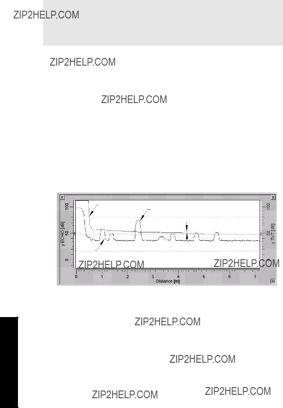

Advanced Shot Adjustment (P840 to P852)
These parameters are for Siemens Milltronics service personnel only.
P840 Short Shot Number
The number of short shots to be fired (and results averaged) per transmit pulse.
P841 Long Shot Number
Enter the number of long shots to be fired (and results averaged) per transmit pulse.
This value is automatically altered by Maximum Process Speed (P003).
Parameters

P842 Short Shot Frequency
Adjust the short shot transmit pulse frequency (in kHz).
This feature is automatically altered when Transducer (P004) is altered.
P843 Long Shot Frequency
Adjust the long shot transmit pulse frequency (in kHz).
This feature is automatically altered when Transducer (P004) is altered.
P844 Short Shot Width
Adjust the width (in ms) of the short shot transmit pulse.
This feature is automatically altered when Transducer (P004) is altered.
P845 Long Shot Width
Adjust the width (in ms) of the long shot transmit pulse.
This feature is automatically altered when Transducer (P004) is altered.
P850 Short Shot Bias
Use this feature to slant the echo evaluation in favour of the short shot echo when both short and long shots are evaluated (see Shot Mode, P803).
P851 Short Shot Floor
Enter the minimum echo strength (in dB above 1 uV) derived from a short shot to be considered for evaluation.
P852 Short Shot Range
Enter the maximum distance in Units (P005) to be measured using short shot echoes.
This feature is automatically altered when Transducer (P004) is altered.
Test (P900 to P913)
Test Parameters are intended for use by Siemens Milltronics Service personnel.
P900 Software Revision Number
View the EPROM Rev. #.
P901 Memory
Press ENTER  to activate the MultiRanger memory test.


P921 Material Measurement
The distance in Units (P005) or % of Span (P007) between Empty (P006) and the monitored surface.
P922 Space Measurement
The distance between the monitored surface and Span (P007).
P923 Distance Measurement
The distance between the monitored surface and the transducer face.
Parameters

P924 Volume Measurement [MR 200]
The calculated vessel capacity in Max Volume (P051) or % of Max Volume.
Please note that Volume Measurement is a MultiRanger 200 feature only.
P925 Flow Measurement [MR 200]
The calculated flowrate in Max Flow (P604) units or % of Max Flow.
Please note that Flow Measurement is a MultiRanger 200 feature only.
P926 Head Measurement [MR 200]
Corresponds to Head (the distance from Zero Head (P605) to the monitored surface in Units (P005) or % of Span (P007).
Please note that Head Measurement is a MultiRanger 200 feature only.
Parameters
P927 Distance Measurement
The distance between the surface and the transducer face (displays only as % of Empty).
Use P923 unless the distance information is required in percent.
Master Reset (P999)
This feature resets all parameters to original values.
Use this feature prior to initial programming if arbitrary Parameter Values were used during a bench test, or after upgrading the software. Following a Master Reset, complete reprogramming is required.
To perform a Master Reset, access P999 and press CLEAR 
 . C.ALL displays until the reset is complete.
In dual point units, both points can be reset at the same time by setting the index to 00 and pressing the CLEAR 
 keys.
keys.
CAUTION: be careful when using this feature. All data for all points will be reset. For convenience, be sure to record the values you want to
Parameters

Notes:
Parameters


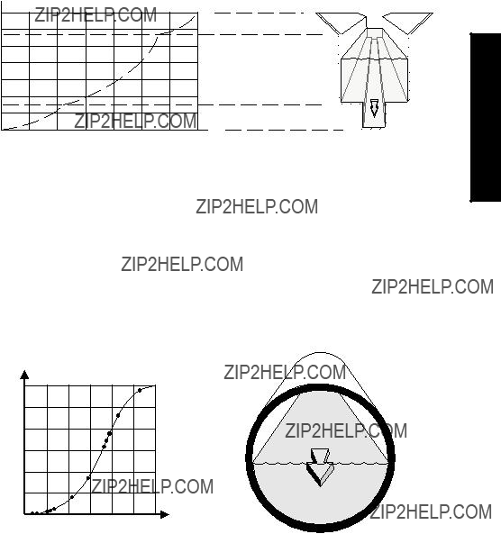


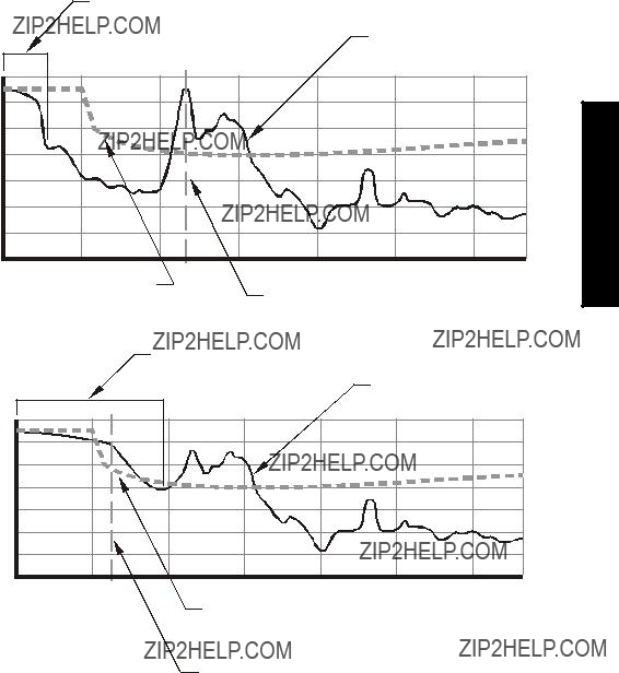


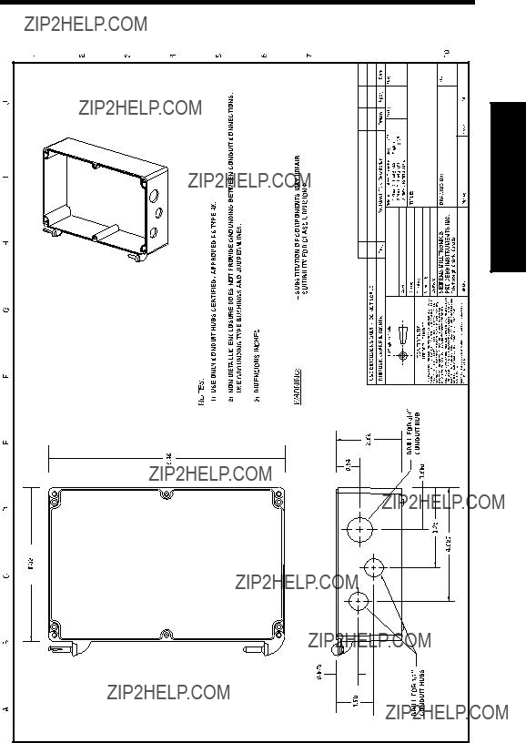
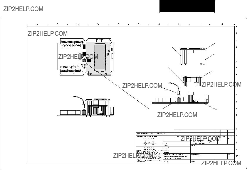


Index

Notes


 . The ammeter should show a value near 4 mA.
 to display the Auxiliary Function symbol.
 to scroll access the failsafe options.
 when the desired option displayed.
 keys.
keys. .
.
 keys to reset these values once the installation is working correctly.
 keys to reset values once the installation is working correctly.
 twice to highlight the index field. The field shows two underscores
 to scroll through the records.
 to copy the echo profile record in the buffer and save it in the selected address in the record library. The parameter value field displays the new record information.
 key to enter display auxiliary mode and then:
 to copy the current echo profile into the buffer for display on Dolphin Plus
 and then ENTER
  to delete the echo profile record in the selected address. The value returns to
  to display the calculated head.
 to display the calculated reading.

 ).
). to display the Auxiliary Function symbol.
 to access the OFF or HOLd option desired.
 is pressed in the RUN mode. See the
  for
for 
 .
.

 . P837 will revert to
  to put the CPU into an infinite loop to test the watchdog timer.
 to activate the display test.
 ,then press each keypad key in the following sequence:


 to supply repeated transmit pulses, at the frequency entered, to the transducer and / or view the transducer operating frequency (automatically altered by
  to test the
  to cycle the scanner relay while firing the transmitter.
 (five times or more to verify stability and overcome any echo lock P711).
 Siemens Milltronics Process Instruments Inc. 2009 Subject to change without prior notice