Type I, Style A
Document No. 96A0027
Issued: November 4, 1985
Rev. L: May 16, 2001
Manufactured to FAA Specification
AC
Copyright ?? 2001 by Siemens Airfield Solutions, Incorporated. All rights reserved.
Type I, Style A
Document No. 96A0027
Issued: November 4, 1985
Rev. L: May 16, 2001
Manufactured to FAA Specification
AC
Copyright ?? 2001 by Siemens Airfield Solutions, Incorporated. All rights reserved.

Record of Changes

Table of Contents

Table of Contents
(Contd.)
List of Figures
List of Tables

Warranties
Disclaimers
Products of Siemens Airfield Solutions manufacture are guaranteed against mechanical, electrical, and physical defects (excluding lamps) for a period of one year from the date of installation or a maximum of two years from the date of shipment and are guaranteed to be merchantable and fit for the ordinary purposes for which such products are made.
Siemens Airfield Solutions will correct by repair or replacement, at its option, equipment or parts which fail because of mechanical, electrical or physical defects, provided that the goods have been properly handled and stored prior to installation, properly installed and properly operated after installation, and provided further that Buyer gives Siemens Airfield Solutions written notice of such defects after delivery of the goods to Buyer.
Siemens Airfield Solutions reserves the right to examine goods upon which a claim is made. Said goods must be presented in the same condition as when the defect therein was discovered. Siemens Airfield Solutions furthers reserves the right to require the return of such goods to establish any claim.
Siemens Airfield Solutions???s obligation under this guarantee is limited to making repair or replacement within a reasonable time after receipt of such written notice and does not include any other costs such as the cost of removal of defective part, installation of repaired product, labor or consequential damages of any kind, the exclusive remedy being to require such new parts to be furnished.
Siemens Airfield Solutions???s liability under no circumstances will exceed the contract price of goods claimed to be defective. Any returns under this guarantee are to be on a transportation charges prepaid basis. For products not manufactured by, but sold by Siemens Airfield Solutions, warranty is limited to that extended by the original manufacturer.
This is Siemens Airfield Solutions???s sole guarantee and warranty with respect to the goods; there are no express warranties or warranties of fitness for any particular purpose or any implied warranties of fitness for any particular purpose or any implied warranties other than those made expressly herein. All such warranties being expressly disclaimed.
This manual could contain technical inaccuracies or typographical errors. Siemens Airfield Solutions reserves the right to revise this manual from time to time in the contents thereof without obligation of Siemens Airfield Solutions to notify any person of such revision or change.
Details and values given in this manual are average values and have been compiled with care. They are not binding, however, and Siemens Airfield Solutions disclaims any liability for damages or detriments suffered as a result of reliance on the information given herein or the use of products, processes or equipment to which this manual refers. No warranty is made that the use of the information or of the products, processes or equipment to which this manual refers will not infringe any third party???s patents or rights. The information given does not release the buyer from making their own experiments and tests.
Type I, Style A
1. Safety
Safety Symbols
This section contains general safety instructions for using your Siemens Airfield Solutions equipment. Some safety instructions may not apply to the equipment in this manual. Task- and
To use this equipment safely,
???refer to the FAA Advisory Circular AC
???observe all safety regulations. To avoid injuries, always remove power prior to making any wire connections and touching any parts. Refer to FAA Advisory Circular AC
???read and become familiar with the general safety instructions provided in this section of the manual before installing, operating, maintaining, or repairing this equipment.
???read and carefully follow the instructions given throughout this manual for performing specific tasks and working with specific equipment.
???store this manual within easy reach of personnel installing, operating, maintaining, or repairing this equipment.
???follow all applicable safety procedures required by your company, industry standards, and government or other regulatory agencies.
???obtain and read Material Safety Data Sheets (MSDS) for all materials used.
Become familiar with the safety symbols presented in this section. These symbols will alert you to safety hazards and conditions that may result in personal injury, death, or property and equipment damage.
WARNING: Failure to observe this warning may result in personal injury, death, or equipment damage.
WARNING: Risk of electrical shock. Failure to observe this warning may result in personal injury, death, or equipment damage.

Safety Symbols (contd.)
Qualified Personnel
WARNING: Disconnect equipment from line voltage. Failure to observe this warning may result in personal injury, death, or equipment damage.
WARNING: Wear safety goggles. Failure to observe may result in serious injury.
CAUTION: Failure to observe may result in equipment damage.
WARNING: Contents are
The term qualified personnel is defined here as individuals who thoroughly understand the equipment and its safe operation, maintenance, and repair. Qualified personnel are physically capable of performing the required tasks, familiar with all relevant safety rules and regulations and have been trained to safely install, operate, maintain, and repair the equipment. It is the responsibility of the company operating this equipment to see that its personnel meet these requirements.
Intended Use
WARNING: Use of this equipment in ways other than described in this manual may result in personal injury, death, or property and equipment damage. Use this equipment only as described in this manual.
Siemens Airfield Solutions cannot be responsible for injuries or damages resulting from nonstandard, unintended applications of its equipment. This equipment is designed and intended only for the purpose described in this manual. Uses not described in this manual are considered unintended uses and may result in serious personal injury, death, or property damage. Unintended uses may result from taking the following actions:
???making changes to equipment that have not been recommended or described in this manual or using parts that are not genuine ADB replacement parts
???failing to make sure that auxiliary equipment complies with approval agency requirements, local codes, and all applicable safety standards
???using materials or auxiliary equipment that are inappropriate or incompatible with your Siemens Airfield Solutions equipment
???allowing unqualified personnel to perform any task

with no impairments in their judgment or reaction times, should operate this equipment.
Read all system component manuals before operating this equipment. A thorough understanding of system components and their operation will help you operate the system safely and efficiently.

Action in the Event of a System or Component Malfunction
Do not operate a system that contains malfunctioning components. If a component malfunctions, turn the system OFF immediately.
???Disconnect and lock out electrical power.
???Allow only qualified personnel to make repairs. Repair or replace the malfunctioning component according to instructions provided in its manual.
Maintenance and Repair
Allow only qualified personnel to perform maintenance, troubleshooting, and repair tasks. Only persons who are properly trained and familiar with Siemens Airfield Solutions equipment are permitted to service this equipment.
???Always use safety devices when working on this equipment.
???Follow the recommended maintenance procedures in your equipment manuals.
???Do not service or adjust any equipment unless another person trained in first aid and CPR is present.
???Connect all disconnected equipment ground cables and wires after servicing equipment. Ground all conductive equipment.
???Use only approved Siemens Airfield Solutions replacement parts. Using unapproved parts or making unapproved modifications to equipment may void agency approvals and create safety hazards.

Maintenance and Repair
(contd.)
???Check interlock systems periodically to ensure their effectiveness.
???Do not attempt to service electrical equipment if standing water is present. Use caution when servicing electrical equipment in a high- humidity environment.
???Use tools with insulated handles when working with electrical equipment.
2. Description
See Figure 1. This section describes the
Introduction (contd.)
Options
The Radio Control has three output relays operated by keying the transmitter in specific sequences. To power these relays, pilots can set their communications transmitters to the frequency to which the
Three clicks of the mike button within five seconds powers the lighting system on the low brightness setting. Five clicks of the mike button within five seconds powers the lighting system on the medium brightness setting. Seven clicks of the mike button within five seconds powers the lighting system on the high brightness setting. The
The contacts of the relays in the
Two options are available for the
Radio Controller Power Handling Capability
An option is available to provide for power handling capability in the Radio Controller, changing the designation to
The entire Radio Controller is completely solid state and has no moving parts other than the relays.
Heater
A heater is available as an option for the

Equipment Specification Data
Table 1 lists supplied equipment and accessories.
1Antenna Kit (includes antenna, coaxial cable and antenna connector)
Continued on next page


Radio Control Restrictions
Use
Interfacing Radio Controller
You can directly connect the Radio Controller to the airport lighting systems or use an interface panel to provide additional switching capabilities or reduce the load on the Radio Controller. Configure the Radio Control system so the runway lights are on whenever the other lighting systems serving the runway are on, except during daytime operations.
Configure the Radio Control system with a day mode to power only those lighting systems that are useful during the day. This mode can be selected automatically by means of a photocell or by a manual switch. Using the day mode, however, means that the daytime IFR procedures associated with the deactivated lighting systems cannot be used.
In areas with heavy voice traffic on the Radio Controller frequency, there may be nuisance activation due to random microphone clicks. If this is a problem, bypass the
When the
During these idle periods, the airport beacon, obstruction lights, and any other lighting systems that are not
Intensity Control
Table 5 provides guidance on how to interface the Radio Control with the intensity settings of the airport lighting system. For example, connect a lighting system with five intensity settings so three clicks of the microphone would power brightness setting 1 or 2, five clicks would power setting 3, and seven clicks would power setting 5. The airport authority may select either setting 1 or 2 for the lowest brightness setting, depending on the background lighting at the airport.

Intensity Control (contd.)
Table 5. Interface of Radio Control with Airport Visual Aids
NOTE: * If runway lights are left on during idle periods, other lighting systems may also be left on at a

Intensity Control (contd.)
REILS
Adapt the Radio Control of REILS to the equipment and the needs of the airport. For one- or
Approach Lights and Edge Lights
When a runway has approach lights that are Radio Controlled and edge lights that are not, the edge lights are left on at an intensity level selected according to the anticipated weather conditions during the hours of night operation. If the runway lights are Radio Controlled and the approach lights are not, then the approach lights may be left off or at a
Photocell Control
Theory of Operation
When the intensity of the lighting system is automatically controlled by a photocell or other means, the Radio Control powers the system. The intensity is selected automatically by the photocell.
This subsection describes the
General
The
Main Assembly
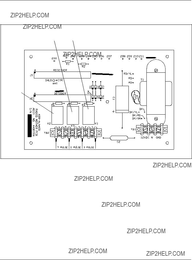
See Figure 2. Power is supplied to the motherboard via terminal block TB1. Fuse F1 protects and switch S1 switches the power to the primary power of transformer T1. T1 has two 120 V ac primary windings that are operated in parallel.

Figure 2.

Main Assembly (contd.)
The secondary power source for T1 is 25.2 V ac,
Interface Panel
See Figure 3. The

Interface Panel (contd.)
Interface Panel (contd.)
Automatic Radio Control
When the Radio Control unit is powered, 120 V ac is connected to relays
K1 and K2 through contact 7A, 5A, or 3A, powering K1 and K2.
Energizing K1 supplies power to the REILS.
If a
If a
If a
Manual Control
See Figure 3. In the manual position, K2 is
If the CCR main rotary control switch is placed in the remote position, either 120 V ac or +48 V dc is output from the CCR at terminal CCI. The CCI voltage is input into the
The photocell supplies 120 V ac to the coil of K1 during the daytime. When K1 is energized, the CCI control voltage is supplied through K1's contacts to the ON/OFF switch. If the switch is placed in the ON position, the CCR is automatically powered at the
Several regulators can be operated together or separately from the same voltage through corresponding switches. In addition, other equipment can be controlled from the

3. Installation
Unpacking
Installing Standard
Interface Panel (contd.)
Other
Multiple configurations for the
WARNING: Allow only qualified personnel to perform the following tasks. Observe and follow the safety instructions in this document and all other related documentation.
This section provides instructions for the installation of the
The equipment must be handled carefully to prevent component damage. Unpack the carton upon receipt and check the contents and their condition. You should find the antenna, the antenna connector, the radio unit, and the antenna
If you find any damage to equipment, file a claim form with the carrier immediately. Inspection of equipment by the carrier may be necessary.
Refer to Installing
To install the standard
1.Determine the best location for the Radio Control.
NOTE: Radio Control location should be within 50 feet (15.24 m) of the antenna and secured to a wall. Consideration should be given to locating it out of a traffic area to reduce or minimize its exposure to unauthorized personnel. Consideration should also be given to the routing of the antenna
2.See Figure 4. Install the radio unit using the four mounting holes.
NOTE: Use four 1/4 x 1 in.- (6.35 x 25.4

Installing Standard
Figure 4. Mounting Dimensions


Figure 5. Assembling Antenna
Installing Standard
(contd.)
3.Connect the end of the coaxial cable terminated with antenna connector to the antenna hub.
NOTE: To prolong the life of the antenna in or around coastal areas, it is recommended that the hardware be encapsulated with a silicon rubber compound such as
Installing Antenna
This subsection describes how to install the antenna.
Safety Precautions
WARNING: Installation of the antenna near power lines is dangerous. For your safety, follow the installation directions.
Each year, hundreds of people are killed, mutilated, or receive severe permanent injuries when attempting to install an antenna. In many of these cases, the victim was aware of the danger of electrocution but did not take adequate settings to avoid the hazard. For your safety, and to achieve a good installation, please read and follow the safety precautions below. They may save your life.
Follow the safety guidelines below.
???Select your installation site with safety, as well as performance, in mind.
???Plan your installation procedure carefully and completely before you begin.
???Successful raising of a mast or tower is largely a matter of coordination.
???Each person should be assigned to a specific task and should know what to do and when to do it. One person should be designated as the master of the operation to call out instructions and watch for signs of trouble.

(contd.)
??Do not use a metal ladder.
??Do not work on a wet or windy day.
??Dress properly - shoes with rubber soles and heels, rubber gloves, long sleeve shirt or jacket.
???If the assembly starts to drop, get away from it and let it fall. Remember, the antenna, mast, cable, and metal guy wires are all excellent conductors of electrical current. Even the slightest touch of any of these parts to a power line completes an electrical path through the antennas and the installer.
Installing
Controller
Mounting Antenna
The antenna should be mounted higher than the roof of the building it is mounted on. It is preferable that it be mounted higher than other obstructions in the immediate area. In the case of a utility pole, mount the antenna part way up the utility pole. If there are other cables or wires running vertically on the utility pole, the vertical part of the antenna should be between 40 in. (1.02 m) and 50 in. (1.27 m) away from the vertical wires/conduit.
To mount the antenna, perform the following procedure:
1.Attach the antenna onto a 1/2 in. (12.7 mm) to 3/4 in. (19.05 mm) pipe or up to
2.Secure the cable to the mounting mast every few feet with strap or plastic tape to avoid strain on cable connections.
3.Remove any unnecessary slack from the coaxial cable and use the supplied field attachable connector to connect the end of the cable to the antenna connector of the Radio Controller.
Installation instructions are the same for the

Installing
Controller (contd.)
The
1.Terminal 1 and Terminal 2 - closes when
2.Terminal 3 and Terminal 4 - closes when
3.Terminal 5 and Terminal 6 - closes when
4.Terminal 7 and Terminal 8 - closes when
5.Terminal 9 and Terminal 10 - closes when
6.Terminal 11 and Terminal 12 - closes when
7.Terminal 13 - line (120 Vac), black wire.
8.Terminal 14 - neutral (120 Vac return), white wire.
9.Terminal 15 ??? earth ground, green wire.
4. Operation
Incremental Relay Option
This section describes operations of the
The
???3 pulses closes the
???5 pulses closes the
???7 pulses closes the
The relay operation can be changed for incremental relay operation, which is as follows:
???3 pulses closes the
???5 pulses closes the
???7 pulses closes the

Incremental Relay Option
(contd.)
See Figure 6. If you want to change the relay operation from individual to incremental, disconnect diodes D3, D4, and D12 on Decoder PCB. Cut these diodes from the Decoder PCB using a diagonal cutter tool.
WARNING: Make sure power to the
To change relay operation from INDIVIDUAL to INCREMENTAL, cut wires on diodes D3, D4, and D12.
Figure 6. Decoder PCB

Controls and Indicators
See Figure 2. Refer to Table 6. All switches, pushbuttons, indication lights, and fuses used in the operation of the
Startup Procedures
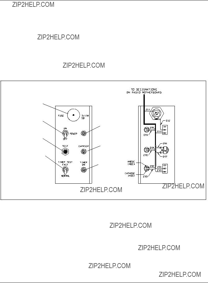
See Figure 7. Startup procedures for the
Figure 7. Control Board and Fuse Assembly
To start up the Radio Control unit, perform the following procedure:
1.Action: Turn power switch to ON.
Result: Red
2.Action: Turn Timer Test Switch S2 to FAST.
3.Action: Depress Test Pushbutton S3 three times within 5 seconds.
Result: The

NOTE: Each time Test Pushbutton S3 is depressed, carrier light DS2 should turn on.

5. Maintenance
Introduction
CAUTION: This equipment contains semiconductor devices and integrated circuits. Static electrical charge buildup in the human body can destroy integrated circuits. Wear a commercially approved ground strap when handling printed circuit boards containing integrated circuits. Wearing a ground strap discharges any static charge buildup to ground and ensures the safety of the integrated circuit. For information on using the ground strap, refer to the ground strap instruction manual.
This section describes maintenance procedures for the
Prior to undertaking any maintenance to this unit, refer to Theory of Operation in the Description section.
The only maintenance recommended by people other than skilled radio technicians is changing the fuses, lamps, PCBs, and
1.See Figure 2. Make sure that power is coming into the unit by measuring the AC voltage across input power line TB1 L to N.
2.Make sure power switch is turned ON. If it is on but the Power On light is out, check fuse F1.
NOTE: If the fuse is blown, replace only with the same size fuse. If the fuse blows again after replacement, consult a repairman to analyze the problem.
3.If the fuse is not blown, but the red power light does not come on, check Power Light DS1.
4.If during the operational test one of the relays (K1, K2, or K3) does not operate, interchange it with one that does operate properly to determine whether the relay or the electronic circuit that activates the relay is defective.
5.If the unit tests properly during an operational test, but cannot be activated from an aircraft, inspect the antenna, antenna connectors, and coaxial
6.If the unit still cannot be activated from an aircraft, check to make sure that the receiver PCB is set to the correct frequency.

Receiver Frequency Setting
See Figure 8. If frequency setting is required, the receiver PCB must be removed from the unit. The frequency setting is accomplished by setting the dip switches S1 and S2 on the receiver PCB to the correct position. For example, to set the receiver frequency at 118 MHz the dip switches S1 and S2 on receiver PCB must be set as follows:
Figure 8. New Receiver PCB Assembly

6. Troubleshooting
WARNING: Allow only qualified personnel to perform the following tasks. Observe and follow the safety instructions in this document and all other related documentation.
WARNING: Make sure power to the
Refer to Table 7. This section provides troubleshooting information for the
Table 7.

6. Troubleshooting (contd.)
Table 7.
7. Parts
Using the Illustrated Parts
List
To order parts, call Siemens Airfield Solutions Customer Service or your local representative. Use this
The Item column numbers correspond to the numbers that identify parts in illustrations following each parts list. NS (not shown) indicates that a listed part is not illustrated.
The Description column gives the part name, as well as its dimensions and other characteristics when appropriate. Indentions show relationships between assemblies, subassemblies, and parts.
The Part Number column gives the Siemens Airfield Solutions part number.
Part Numbering System
The Note column contains letters that refer to notes at the end of each parts list. Notes contain special ordering information.
Figure 9 shows how to determine the part number for a particular

Part Numbering System
(contd.)
44A4710 - X X
Type
1 =
Relay
4 =
SS
6 =
Heater
1 = Without Heater (Down to 35 ??C)
2 = With Heater (Down to
Figure 9.
List
See Figure 10.

Figure 10. Main Assembly
Assembly Parts List
See Figure 11.
Assembly Parts List (contd.)
Figure 11. Motherboard
Fuse Assembly Parts List
See Figure 12.
Figure 12. Control Board and Fuse Assembly


