This catalog is out of date, see note on page 3
Catalog PLT 112 ?? 2002
teleperm m
AS 488/TM automation systems
This catalog is out of date, see note on page 3
Catalog PLT 112 ?? 2002
teleperm m
AS 488/TM automation systems

This catalog is out of date, see note on page 3
Related catalogs
Order No.:
on
Automation and Drives
The Entire Product Range on
Order No.:
Trademarks
All names in this catalog identified by ?? are registered trademarks of the Siemens AG.
All other product and system names are (registered) trademarks of their respective owners and must be treated accordingly.
CA 01
Internet
Visit our Automation and Drives Technology Site in the Internet!
Our address is
www.siemens.com/automation

AS 488/TM automation systems
Catalog PLT 112 ?? 2002
The products in this catalog are also included in the
Order No.:
Please contact your local Siemens office or representative.
This catalog is no longer available in printed form. However, it can still be used to obtain information and for ordering spare parts.
Certain products from this catalog are no longer available. Your Siemens partner will offer appropriate substitutes wherever possible.
This catalog is out of date, see note on page 3
Introduction
Siemens PLT 112 ?? 2002
This catalog is out of date, see note on page 3
Introduction
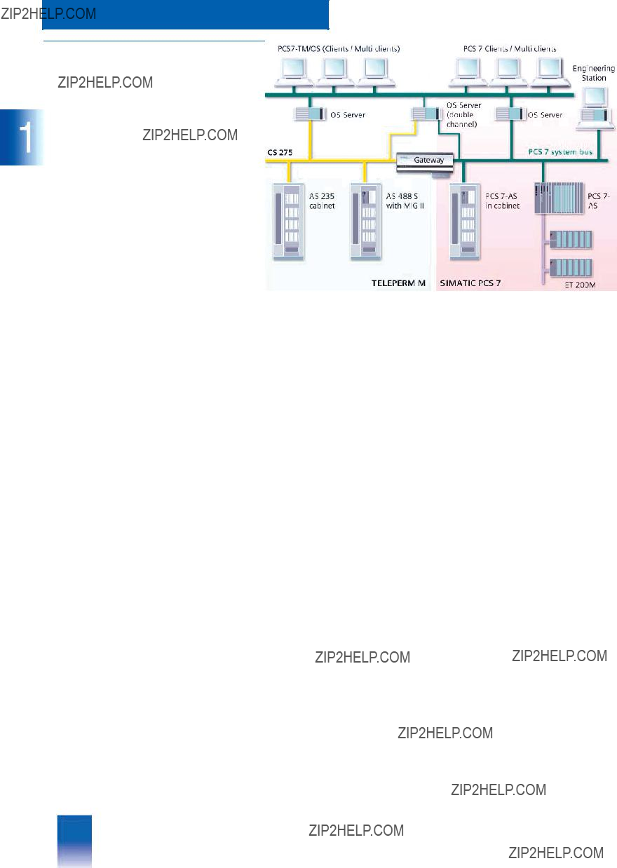
TELEPERM M Process Control System
???Overview
The TELEPERM M process control system pro- vides all functions required for process automa- tion. It is highly suitable for the complete automation of continuous or discontinuous (batch) processes.
The TELEPERM M systems are divided into functional units optimized for different task en- countered with process automation:
???Automation systems
???Operator systems
???Bus systems.
Automation systems
The TELEPERM M automation system of type AS 488/TM based on the SIMATIC
The system software functions of the AS 488/TM are compatible with the system software version G of the previous AS 235 sys- tem. Existing application software of the AS 230 / AS 235 auto- mation systems can be used further, application software of AS 220 automation systems only following conversion.
The AS 488/TM can be operated on both the CS 275 and
Application details:
???Replacement of existing AS 220 / AS 230 / AS 235 automation systems during migration by replacement of the existing basic rack by a preassembled rack with the AS 488/TM system
???Expansion of existing systems on the CS 275 system bus
???Expansion of existing systems by
???New systems
In the case of new systems, the
A wide range of TELEPERM M input/output modules is available for the AS 488/TM, some of which have their own processing functions or are configurable specific to the application. Via one or two
ET 200U distributed I/O systems with a comprehensive selection of I/O modules. Within this range, the I/O modules of the
ET 200M distributed I/O system which have been specially tai- lored to process engineering are particularly recommendable.
A large number of devices possessing a DP interface can be ad- ditionally operated on the
AS 488/TM. Gateway modules on the
access to the
Operator systems
The
HMI component for the AS 488/TM and the TELEPERM M AS 220 S / AS 220 H, AS 215, AS 230 / AS 230 K, AS 235 /
AS 235 K / AS 235 H and AS 388/TM automation systems which are no longer actively marketed. It communicates with the subordinate TELEPERM M automation systems and with SIMATIC
The variable configuration of the
The wide variety of

This catalog is out of date, see note on page 3
Introduction
Engineering
The PROGRAF AS+/NT configuring software which can be in- stalled on personal computers with the Windows NT or Windows 2000 operating system is predestined for the engi- neering of TELEPERM M automation systems. An engineering PC with PROGRAF AS+/NT can be connected to one of the two TELEPERM M system buses using a
PROGRAF AS+/NT can be used to graphically configure, test, optimize and document the application software of the TELEPERM M automation systems. The configurations of previ- ously installed automation systems can also be read in, recom- piled and subsequently processed further or documented in graphic form. Any
System bus
The system bus is the central communication component of ev- ery distributed process control system. Two different bus sys- tems are available for the TELEPERM M process control system, and can also be combined together within a plant:
???CS 275
???
The CS 275 bus system which has been proven in many auto- mation plants functions according to the token passing principle and can also have a redundant configuration. Several buses can be combined together using bus couplers such that bus net- works are produced corresponding to the plant structure. The bus system is provided with distributed control. The bus inter- face of each subsystem may take over the master function ac- cording to specific criteria.
The
All automation systems and operator systems of the TELEPERM M process control system can be operated on the CS 275 system bus, but only the current AS 488/TM and
TELEPERM M Process Control System
Migration strategy
The purpose of migration of the proven TELEPERM M process control system into the new,
Migration is divided into the following steps:
???Innovation
-Migration of the TELEPERM M process control system by re- newal of components close to the process (automation sys- tems) and of
-Expansion of the process I/Os for the innovative automation systems by integration of the ET 200M, ET 200S, ET 200U and ET 200X distributed I/Os and of the
-Linking of the existing CS 275 system bus to the new
-Integration of SIMATIC S5, SIMATIC S7 and SIMATIC PCS 7 systems with data coupling via
???Combination
Standardization of the HMI components of the TELEPERM M and SIMATIC PCS 7 systems on the basis of the SIMATIC PCS 7 operator station, as well as combination of partial TELEPERM M and SIMATIC PCS 7 systems with these com- mon HMI components
???Homogenization
Replacement of the TELEPERM M automation systems by SIMATIC PCS 7 automation systems with further use of existing TELEPERM M I/Os
This catalog is out of date, see note on page 3
Introduction
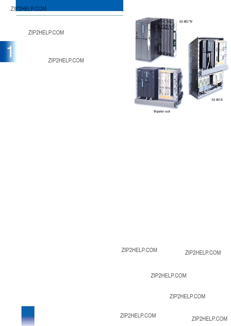
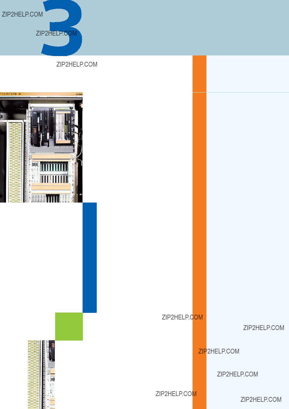
AS 488/TM
???Overview
The AS 488/TM automation system based on the
SIMATIC
The functions of the AS 488/TM system software are compatible with the G system software of the previous AS 235 system. Thus you can continue to use existing application software of the
AS 220 / AS 230 / AS 235 automation systems with its standard function blocks, user function blocks, TML programs and STEP M programs. AS 220 application software, however, must first be converted (service is part of migration offer).
The AS 488/TM automation system is available in four different versions:
???AS 488 with modular, standard packaging system for connec- tion at the rear according to the SIMATIC guidelines
???AS 488 S cabinet system for installation in TELEPERM M cabi- nets with 19" packaging system (cabinets not included in scope of delivery of AS 488 S, they must be ordered as options if required from Catalog PLT 111)
???AS 488, installed in SIMATIC PCS 7 cabinets (only with exclu- sive use of distributed SIMATIC I/Os; see Catalog ST PCS7.A,
???AS 488 K compact system for installation in TELEPERM M wall housings or cabinets
The AS 488 K compact system and the AS 488 S cabinet system provide numerous possibilities for system expansion and mod- ernization by replacement of TELEPERM M automation systems which are no longer available or marketed, with a simultaneous increase in the AS performance. The completely equipped
AS 488 K / AS 488 S basic systems which have been pretested by means of a
I/O modules can be directly inserted into the MIG II and MIG K migration racks just like in the basic unit of an AS 235 or
AS 235 K.
As with the AS 230 / AS 235, up to three extension units can be operated in the basic cabinet on I/O bus A of an AS 488 S as well as an external ES 100 K. Up to four extension units of an AS 230 / AS 235 extension cabinet can be connected to an
AS 488 S via I/O bus B if the ribbon cable for the I/O bus is re- placed. During migration off the AS 488/TM it is therefore possi- ble to add a fourth extension unit to a maximally configured
AS 235 extension cabinet. Limitation of the number of migratable I/O modules does not therefore exist for an AS 230 / AS 235 con- figured with the maximum number of TELEPERM M I/O modules.
The AS 488 K with its MIG K migration rack offers the same packaging system as an AS 235 K. The MIG K migration rack has five slots for TELEPERM M I/O modules. The serial coupling known from the AS 235 K permits connection of 2 x 4 ES 100 K compact extension systems. These can be positioned up to 500 m away from the AS 488 K automation system, and are therefore highly suitable for a distributed configuration.
In addition to the migration of existing TELEPERM M I/Os, all ver- sions of the AS 488/TM automation system can also be extended by distributed I/Os on the
ET 200M system with a comprehensive range of I/O modules specially designed for process engineering, it is also possible to use the SIMATIC ET 200B, ET 200S, ET 200iS, ET 200X and ET 200U I/O systems (the latter is no longer actively marketed). It is additionally possible to operate a wide range of devices possessing a DP interface on the
AS 488/TM. For example, DP interfaces integrated in the
CPU modules of the SIMATIC
The homogeneous interfacing of the distributed SIMATIC I/Os forces distribution close to the process. Significant cost savings are therefore achieved for the process I/Os as well as for field wiring and routing.
The AS 488 S is optimized for installation in TELEPERM M cabi- nets with 19" packaging system, and therefore particularly suit- able for the migration or expansion of existing TELEPERM M systems. The system is mounted on the front cabinet members. The TELEPERM M installation guidelines are applicable with re- spect to the CE marking wherever TELEPERM M I/O modules are operated in an AS 488 S. On the other hand, the SIMATIC S7/M7 guidelines apply to an AS 488 S exclusively operating with distributed I/Os on the

This catalog is out of date, see note on page 3
Introduction
AS 488/TM systems for new plants exclusively with distributed I/Os on the
SIMATIC PCS 7 cabinets. The SIMATIC S7/M7 installation guidelines also apply to this version (see Catalog ST PCS7.A,
Customers can select between two CPUs with different perfor- mance levels for all design versions of the AS 488/TM:
???SIMATIC M7 CPU
???SIMATIC M7 CPU
A commissioning terminal based on PC/programming device can be used for commissioning of the AS 488/TM. The terminal is connected via a serial interface to the respective AS 488/TM and offers the user the same GUI and syntax as known from the AS 235. Because of the serial interface, not all HMI requirements can be fulfilled. Furthermore, the commissioning terminal is not suitable for operation/configuring of another AS using the
AS bus configuration channel.
PROGRAF AS+/NT is a convenient configuring tool for the
AS 488/TM automation systems. It is compatible with all AS 23x systems. PROGRAF AS+/NT executes on an appropriate PC/programming device with Windows NT/2000/XP operating system and connection to the CS
???Highlights
Classification in the TELEPERM M system environment
Note:
Some of the communications partners/systems referred to below are no longer available or no longer marketed. Reference to the systems in the context "Classification in the TELEPERM M sys- tem environment" does not permit any conclusions to be made on their availability.
???Communications capability with existing systems and I/O modules
All automation systems and operator systems of the TELEPERM M process control system can be operated on the CS 275 system bus. Only the current AS 488/TM and
AS 488/TM systems respond on the system bus like an AS 235 system with compatible functions compared to the
-AS 388/TM or AS 488/TM automation systems on the
AS 230, AS 230 K, AS 235, AS 235 H, AS 235 K, AS 488/TM on the CS 275 system bus
-OS 525, OS 525 Local or
-Engineering systems: personal computer with the PROGRAF AS+/NT program package, personal computer or ES 500 with the PROGRAF AS+ program package, on the CS 275 or
AS 488/TM
-Other systems
SIMATIC PCS 7, SIMATIC S7, SIMATIC S5 and systems from other vendors via the DP bus
???Limitations in communication
-The response of the AS 488/TM and AS 388/TM systems in a homogeneous network with approved TELEPERM M stations on the CS 275 or
OS 525,
When communicating with other stations (e.g. systems from other vendors) via the
-Use of the
-Use of the AS bus configuring channel for operation/configur- ing of another AS using a commissioning terminal is not re- leased because of the serial communications mode of the commissioning terminal.
-Communication to the process I/Os is carried out via serial
AS 388/TM and AS 488/TM automation systems each have two
-The AS 488/TM communicates with existing I/O modules from the TELEPERM M range via a special interface module and the parallel I/O bus interface (ribbon cable) in the TELEPERM M cabinets.
-The process image is automatically generated by the inter- face module, and this module must therefore recognize the connected I/O modules. Only those modules and systems listed in the Section "Migration of existing systems" or pub- lished on the Internet "AS 488/TM configuration list" can be used.
???
The AS 488/TM automation system does not offer a compatible replacement for the

This catalog is out of date, see note on page 3
Introduction
AS 488/TM
???Area of application
The main applications of the AS 488/TM are:
???Replacement of existing AS 220, AS 230/230 K and AS 235/235 K automation systems
With an AS 220 / AS 230 / AS 235, the subrack with the central processing units in the TELEPERM M cabinet is replaced by an AS 488 S with compatible functions. Existing extension units with installed TELEPERM M I/Os can be used further. With an AS 230 K / AS 235 K, migration is carried out by replacing the complete basic system in the TELEPERM M housing, rack or cabinet by an AS 488 K compact system with compatible func- tions. TELEPERM M I/O modules previously inserted in the
AS 230 K / AS 235 K basic system can be used further follow- ing conversion and rewiring in the migration rack of the
AS 488 K.
When replacing existing automation systems, the AS 488 S and AS 488 K migration systems are preferably connected to the existing CS 275 system bus. Alternatively possible is con- nection to the
???Expansion of existing TELEPERM M systems on the CS 275 system bus
Expansions on the CS 275 system bus are mainly the result of modernization by migration with AS 488/TM. Existing systems with TELEPERM M I/Os can also be expanded by SIMATIC dis- tributed I/Os on the
???Expansion of existing TELEPERM M systems by
Existing and new system components can be connected to- gether using a
Distributed SIMATIC I/Os on the
AS 488/TM.
???New systems with the AS 488/T M automation system
In the case of new systems, it is recommendable to use the
The favorite standard within the ET 200 range is the ET 200M I/O system with a comprehensive range of I/O modules of SIMATIC
???Functions
Highlights
???Functions compatible with the proven AS 235 automation sys- tems: existing application software and installed process I/Os can be used further
???
continuous evolution to new technologies with the modern hardware platform of the SIMATIC M7 systems
???Two performance ranges:
selectable CPU performance corresponding to 150% or 270 to 300% of the performance of an AS 235
???Four design systems:
-AS 488 in modular standard packaging system according to SIMATIC guidelines
-AS 488 S cabinet system for installation in TELEPERM M cab- inets
-AS 488, installed in SIMATIC PCS 7 cabinets
-AS 488 K compact system for installation in TELEPERM M wall housing or cabinets
???Can be used for modernization and expansion of existing sys- tems and also for new systems
???Flexible adaptation of automation system to the respective task:
-Comprehensive range of distributed I/Os
-ET 200M I/Os especially suitable for process engineering
-Compact modules in adapter casings, operation without fans
-Adaptable packaging system
-Migration of existing TELEPERM M systems
???Modern communication standards:
-
-
???
???Bridge for connection of CS 275 and
This catalog is out of date, see note on page 3
System architecture
Siemens PLT 112 ?? 2002
This catalog is out of date, see note on page 3
System architecture
System properties
???Overview
The AS 488/TM automation system consists of standard hard- ware components from the SIMATIC M7 systems, supplementa- ry components for applications in TELEPERM M, and a memory card with system software whose functions are compatible with the AS 235 automation system.
All system programs are saved permanently on the memory card of the AS 488/TM automation system. The user configura- tions are also saved permanently on the same medium.
The main characteristic of the AS 488/TM system software is the complete simulation of the AS 235 functions on the basis of an RMOS32
The system software permits configuring of the automation func- tions as with the AS 235 system (using dedicated function blocks, TML and STEP M programs) as well as communication via a system bus.
The AS 488/TM automation systems are available in four differ- ent versions to permit optimum adaptation to different customer requirements:
???As AS 488 with the modular SIMATIC
???As AS 488 S cabinet system: SIMATIC
???As AS 488 with SIMATIC
???As AS 488 K compact system: SIMATIC
The AS 488/TM system with the CPU
Exceptional features of the automation systems are their univer- sal functions for automation tasks, compatibility with the AS 235 systems, as well as the communication capability with the PROGRAF AS+/NT configuring tool, the
Both continuous processes and comprehensive batch process- es (production procedure repeated in same or modified form) can be automated by the AS 488/TM system.
The automation systems have a minimum cycle time of 125 ms for
???Functions
???Automation system with graded performance and communica- tion via system bus
???
???Central operation and monitoring with the
???Configuring with graphical user interface using the PROGRAF AS+/NT engineering tool on PC/programming de- vice
???Commissioning support with commissioning terminal based on PC/programming device with known TELEPERM M syntax
???SIMATIC S7/M7 packaging system; integration in TELEPERM M cabinets/housing with MIG I, MIG II or MIG K migration racks
???Distributed I/Os with the modular ET 200M I/O stations (includ- ing Ex(i) modules), ET 200B, ET 200U, ET 200S, ET 200iS (available soon) and ET 200X
???TELEPERM M I/O modules in standard TELEPERM M cabinets with AS 488 S / AS 488 K migration packages
???The
???System programs on memory card plus user area for archiving
???4 Mbyte user memory
???
???Complete range of standard function blocks, identical to the AS 235 system
???User function blocks with convenient TML programming lan- guage, or also the STEP M programming language for open- loop controls
???Online configuring/programming with graphic support by
PROGRAF AS+/NT
???Compatible with preconfigured SIGRID TM V5 (GF/GFE), BATCH
???Reloadable software packages with couplings and I/O links:
-
-
-
-SIWAREX M
-
-
-
-Options: special driver blocks for use of SIMOVERT, MICRODRIVES, SIPART DR, FM 350, CEAG devices, etc.
This catalog is out of date, see note on page 3
System architecture
System properties
???Technical Specifications
Quantity breakdown
The AS 488/TM automation systems have the following quantity breakdowns:
*) The values identified by an asterisk apply as alternatives and are not for addition.

This catalog is out of date, see note on page 3
System architecture
System software
???User function blocks
Overview
A separate memory card with system software is required for each automation system. The system software of the AS 488/TM is completely present on this memory card, and only executes there. The software is reloaded each time the system is switched on or reset. The memory card is divided into a system memory and a user memory. The system memory is
The memory card is inserted into a special slot in the automation system???s CPU. It must not be removed during operation, it must remain permanently inserted in the CPU.
Standard function blocks
Dedicated function blocks, the
Supported by the powerful PROGRAF AS graphic configuring tool, the standard function blocks present in the system software are activated by means of configuring instructions and linked into an automation structure which is partially processed cycli- cally by the automation system???s CPU, and partially also acycli- cally.
The standard function blocks of the AS 488/TM system are listed in the tables under "Configuring". Blocks have been omitted which are still in the system software for compatibility reasons but have no significance any longer for applications with the AS 488/TM.
Optional function blocks
Various preconfigured standard software packages are avail- able which can be subsequently loaded and executed on the AS 488/TM. Compatibility with the AS 488/TM system software is guaranteed for the following packages:
If the standard function blocks are insufficient to fulfil the control, operation, monitoring and communication tasks, the TML pro- cess language (TELEPERM M Language) can be used for ana- log and binary processing operations, and the STEP M control language for binary logic operations. TML and STEP M can be used to define new function blocks optimally tailored to the re- spective automation task.
Functions which can only be solved with difficulty using stan- dard function blocks, e.g. optimization, startup and shutdown, or
TML language
TML is used to produce more complex blocks for comprehen- sive analog, binary and character processing functions with in- dividual test and processing algorithms. TML is particularly suitable if many functions of the same type are to be linked with different signals, addresses or parameters (multiplex system).
STEP M language
Binary functions such as linking, saving and time delays are re- quired for sequential and logic controls. The main component of STEP M is the logic operation with which scanning, linking, set- ting, resetting and assignment instructions can be formulated.
Parts of the program which are used repeatedly can be trans- ferred into subroutines.
Note:
The following software packages can also be used, but are no longer actively marketed:
???SIGRID TM V5 (basic process engineering functions and basic function elements)
???BATCH
???FUZZY TM (configuration of fuzzy controls)
The SIGRID TM V5, BATCH

This catalog is out of date, see note on page 3
System architecture
???Configuration
Listing of TELEPERM M standard function blocks
Data blocks
Blocks for analog and digital processing

This catalog is out of date, see note on page 3
System architecture
System software
Blocks for processing with standardized operation and monitoring
BOperator communi- ??? Display of analog values (e.g. internal
Blocks for signal exchange via the CS 275 or

This catalog is out of date, see note on page 3
System architecture
System software
Driver blocks for I/O modules of the TELEPERM M system via the TPM 478 communications module
This catalog is out of date, see note on page 3
System architecture
System software
Blocks for I/O modules with standardized display
6DS1
6DS1
Organization blocks
Test blocks

This catalog is out of date, see note on page 3
System architecture
Commissioning
???Overview
A commissioning terminal is required for commissioning and system configuring of the AS 488/TM or the
Commissioning terminal
The commissioning terminal is required for the following tasks:
???System configuring for bus communication and I/Os
???To edit initialization files on the memory card, e.g. to set the bus and station addresses
???To describe hardware configurations, e.g. I/O stations on the
???Archiving of user software on the memory card
???Commissioning
???Downloading of initialization and driver software onto the mem- ory card, e.g. for the 2nd
Together with the commissioning terminal software belonging to the system software, any personal computer/programming de- vice can be used as the commissioning terminal if it satisfies the following requirements:
DOS version of commissioning terminal software
???CPU with 80386, 80486 or Pentium processor
???Vacant main memory min. 320 Kbyte
???VGA graphics (min. resolution 640 x 480)
???One vacant serial COM port
???
???Microsoft Windows 3.1 or Windows for Workgroups 3.11 oper- ating system for the COM PROFIBUS configuring software
(if required, see Section "Process I/Os").
NT version of commissioning terminal software
???CPU with Pentium processor
???Vacant hard disk capacity approx. 5.1 Mbyte
???One vacant serial COM port
???
???Microsoft Windows NT (V 4.0 or later) or Windows 2000 oper- ating system.
Both versions are included in the delivery of the system software.
???Design
Cable for connection of the commissioning terminal
The commissioning terminal for the AS 488/TM automation systems and the
IF
The IF
Notes on operation of the commissioning terminal
The commissioning terminal supports use of the known opera- tion and monitoring interface of the automation system for com- missioning and servicing purposes, but without offering the quality of an operation and monitoring system.
The commissioning terminal can be permanently connected to the automation system. The serial data transmission rate is 19.2 kbit/s.
Communication between the AS and the commissioning termi- nal is automatically resynchronized following an interruption, e.g. as a result of message interferences.
For diagnostics purposes or for setting parameters, AS opera- tions according to AS 235 conventions are also possible using the commissioning terminal. However, the operation/configura- tion of another automation system using the AS bus configuring channel is not permissible. As a result of the serial interface, the commissioning terminal is certainly not an adequate substitute for an operator system or engineering system.
The AS and PC systems must be electrically isolated from one another if the distances between the earth potentials are greater than 10 m.
???Ordering Data
This catalog is out of date, see note on page 3
System architecture
Engineering with PROGRAF AS+
???Overview
PROGRAF AS+/NT is a powerful
PROGRAF AS+/NT can be used to graphically configure, test, optimize and document the application software of the TELEPERM M automation systems. In contrast to comparable products from other vendors, PROGRAF AS+/NT also permits reading, recompilation and subsequent further graphical pro- cessing or documentation of the structures of already installed automation systems. Features such as the function diagram ed- itor with online testing and curve display, the libraries for ele- ments for repeated use, and the import functions make PROGRAF AS+/NT an indispensable aid for AS engineering.
PROGRAF AS+/NT also offers operation and monitoring facilities on the CS 275 system bus, corresponding to local operation of an AS 235.
PROGRAF AS+/NT supersedes the proven PROGRAF AS+ en- gineering tool which only executes on the Microsoft Windows 3.1 operating system. The new tool has complete function and data compatibility with the previous product. User data generated with PROGRAF AS+ can be processed further with
PROGRAF AS+/NT, and vice versa.
As a result of its versatile functions as well as supporting of test- ing, commissioning and optimization, PROGRAF AS+/NT is par- ticularly suitable
??? for TELEPERM M customers carrying out
???Functions
The PROGRAF AS+/NT program features the following func- tions:
Powerful graphic function diagram editor
The function diagram editor provides a hierarchical breakdown, zoom functions, and
All standard function blocks are available as well as user func- tion blocks generated using PROGRAF AS+/NT or read out of an automation system.
PROGRAF AS+/NT provides a breakdown into function areas, function groups and function diagrams for individual process functions in order to map hierarchical identification systems. The window system permits two pages to be displayed on the screen, e.g. in order to link function blocks from different groups.
???for consultants specialized in TELEPERM M configuring, and
???for
One of the most important functions is the autorouter which rap- idly and automatically draws the links between function blocks.
If a block is shifted - even onto another page - the autorouter au- tomatically updates the connection lines, connectors and also the contents of the margins.
Bus connection
PROGRAF AS+/NT supports the new
Just like PROGRAF AS+, the PROGRAF AS+/NT can also be used together with the
Note:
The CP 5412(A2) communications processor is still available un- der Order No. 6GK1
Closed data cycle
All entered user data are immediately checked by the integral database, and saved centrally. Subsequent modifications can always be read into PROGRAF AS+/NT and updated there auto- matically. The data thus remain consistent in both systems.
The database uses this information to automatically generate a loading sequence with instructions for the automation system. This loading sequence is transmitted to the automation system via the system bus.
It is also possible to load an
This catalog is out of date, see note on page 3
System architecture
Engineering with PROGRAF AS+
Configuration of
PROGRAF AS+/NT can be used to generate
These library elements include process functions, user function blocks and programs.
When storing on a server, central libraries can be produced for networked PCs, thus permitting several engineers to access the current library objects.
Special library elements in PROGRAF AS+/NT are the
Standard diagrams are generated by transferring an individual function diagram into a library. They are automatically assigned general diagram variables. The configuring engineer can also define his own variables. The desired standard diagrams can be called from the library and assigned the respectively required data for the variables.
Complete, automatically generated documentation
Complete documentation includes the following individual doc- uments:
???List of contents
???Graphic documentation of block configurations (function dia- grams)
???Graphic function diagrams of the STEP programs
???Structograms of the TML programs for user function blocks
???Documentation of TML and STEP programs and process dis- play instructions in the form of lists
???Documentation of the block sequence, the blocks not inserted into the processing sequence, as well as the driver and cou- pling blocks in the form of lists
???Various
The documentation is independent of whether
PROGRAF AS+/NT was used for configuring or whether the data have been read out of an automation system and decompiled.
Documentation of individual parts of the AS configuration is also possible.
Central workstation for control engineer
Complete configurations, delta loading lists (only changes in configuration) and partial configurations (for test purposes) can be loaded by PROGRAF AS+/NT into the automation systems.
PROGRAF AS+/NT also permits the central exchange of
During the commissioning phase, PROGRAF AS+/NT is the cen- tral engineering workstation for the control engineer. A local
AS configuration desktop is emulated on his monitor like with the AS 235 system (AS terminal emulation). The process variables are updated cyclically.
Central online commissioning
with AS terminal emulation and display of dynamic values and curves directly in the function diagram editor, e.g. for optimiza- tion of control loops. Up to four process values can be displayed as curves. Parameters modified in this online mode can also be written into the database of PROGRAF AS+/NT in order to guar- antee data consistency.
Data import and export
There are external interfaces from the database: data from exter- nal planning tools can be imported into PROGRAF AS+/NT.
???Technical Specifications
Hardware requirements
???Graphics card resolution min. 1024 x 768, min. 32768 colors
???
???3.5" diskette drive as well as a 5.25" drive for reading the AS diskettes
???PostScript laser printer.
Software requirements
???MS Windows NT 4.0 or MS Windows 2000 or Windows XP op- erating system
Note: no operating system software is included in the delivery of PROGRAF AS+/NT.
Automation systems released for PROGRAF AS+/NT:
???AS 230, AS 230 K, AS 235, AS 235 K, AS 235 H as well as AS 388/TM and AS 488/TM automation systems
???The system software release F3.02 is required for unlimited use of PROGRAF AS+/NT with the
The following limitations otherwise apply:
???With AS 230, version B, C or D, the AS diskette format must first be converted to the format of the AS 230, version E.
???
This catalog is out of date, see note on page 3
System architecture
Engineering with PROGRAF AS+
???Accessories
Ordering Data
comprising:
???1 software CD with program package in German and English
???Software protection (dongle)
PC components (ISA) for connection to TELEPERM M system bus
Order No.
CP 5412 (A2) communications
comprising:
???CP 5412 (A2)
???Firmware on 3.5" diskette
Obsolescent product
Configuring software for CP 5412 (A2) on
Obsolescent product
PC components (PCI) for connection to TELEPERM M system bus
Order No.
CP 5613 communications pro- 6GK1
comprising:
???CP 5613 (PCI card)
???
Configuring software for CP 5613 on

This catalog is out of date, see note on page 3
System architecture
This catalog is out of date, see note on page 3
AS 488 S Cabinet system
3/2 AS 488 S cabinet system
3/2 Overview
3/2 Ordering data
3/2 Scope of delivery of AS 488 S systems 3/4 Accessories
Siemens PLT 112 ?? 2002
This catalog is out of date, see note on page 3
Cabinet system
AS 488 S
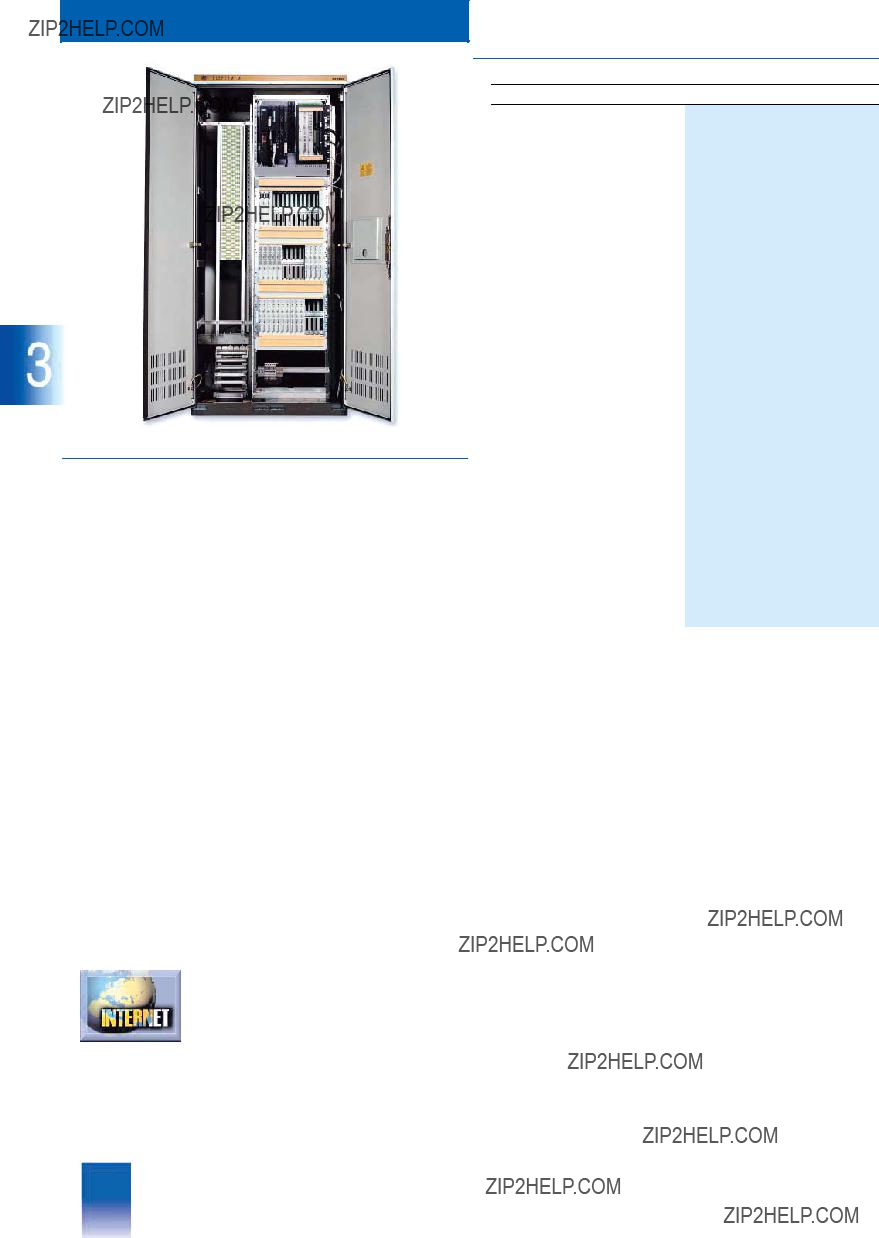
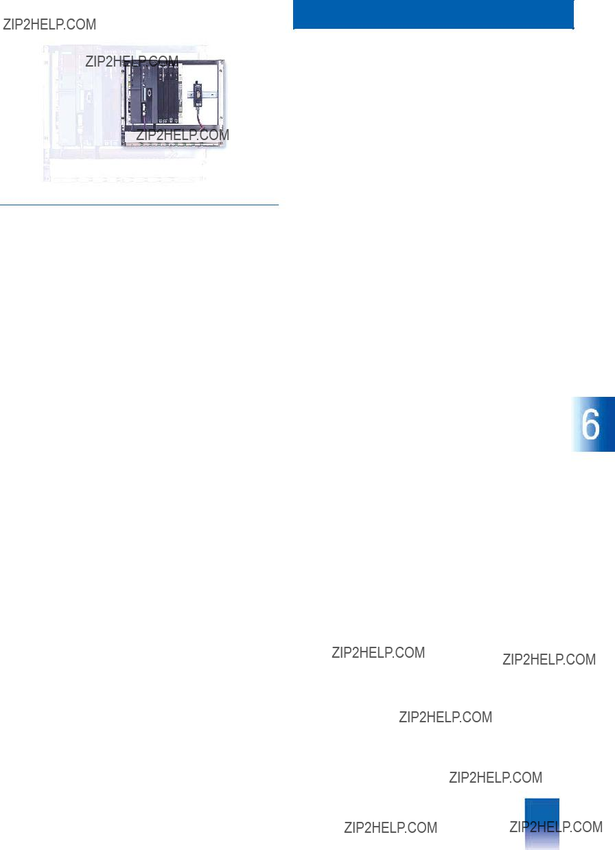
AS 488 S cabinet system
???Overview
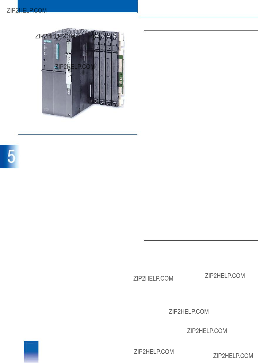
The AS 488 S cabinet system is one of four design versions of the AS 488/TM automation system.
The AS 488 S is specially designed for migration or expansion of existing TELEPERM M systems, and therefore optimized for in- stallation in TELEPERM M cabinets with 19" packaging systems. The AS 488 S preassembled on an MIG I or MIG II migration rack is mounted on the front cabinet members of a TELEPERM M cabinet. The TELEPERM M installation guidelines are applicable with respect to the CE marking wherever TELEPERM M
I/O modules are operated in an AS 488 S. On the other hand, the SIMATIC S7/M7 guidelines apply to an AS 488 S exclusively operating with distributed I/Os on the
In contrast to a system order in the form of individual compo- nents (the orderer is responsible for logistics and assembly), a completely equipped and pretested AS 488 S is ordered using a single Order No. specified by the selection of defined standards. The standards differ depending on whether TELEPERM M I/O modules are used (cabinet packaging system according to TELEPERM M guidelines) or not (cabinet packag- ing system according to SIMATIC guidelines), and vary with re- spect to the type of CPU (120 MHz or 75 MHz), the power supply (DC 24 V or AC 230 V) and the migration rack (MIG I or MIG II). In addition, supplementary components and parts ??? including any TELEPERM M cabinets required ??? can be ordered as indi- vidual options as previously.
Please order any TELEPERM M cabinets required using Catalog PLT 111. You can download this catalog from the Internet.
???Ordering Data
Order No.
???Migration rack I
???
???SIMATIC 19" packaging system
???System software
???CPU 120 MHz
Scope of delivery of AS 488 S systems
The complete Order Nos. defined above contain the following components:
Basic system
???SIMATIC M7 CPU
CPU
???SIMATIC M7 CPU
CPU
???Memory modules for CPU
???Expansion and interface modules:
-1 x IF
-1 x IF
Additional information is available in the Internet under:
www.siemens.com/teleperm

This catalog is out of date, see note on page 3
Cabinet system
AS 488 S
Power supply
???AS 488 S systems, versions 1, 2, 3 and 4, for operation with TELEPERM M I/O modules
-PS 405 load power supply, 20 A, TELEPERM M packaging system
Input: DC 24 V, output: DC 24 V/DC 5 V, 20 A, width: 3 standard slots
-2 backup batteries type AA; 3.6 V; 1.9 Ah (for buffering of time)
???AS 488 S systems, versions 5 and 6, with
-PS 407 load power supply, 10 A
Input: AC 230 V, output: DC 5 V, 10 A, width: 2 standard slots
-2 backup batteries type AA; 3.6 V; 1.9 Ah (for buffering of time)
???AS 488 S systems, versions 7 and 8, with
-PS 405 load power supply, 10 A
Input: DC 24 V, output: DC 24 V/DC 5 V, 10 A, width: 2 standard slots
-2 backup batteries type AA; 3.6 V; 1.9 Ah (for buffering of time)
Packaging system/migration racks
???MIG II migration rack for AS 488 S (design alternative 1, system versions 1 and 2) with integral UR2 rack, 5 slots for TELEPERM M I/O modules
???MIG I migration rack for AS 488 S (design alternative 2, system versions 3 to 8) with integral UR2 rack, without TELEPERM M I/O slots
TELEPERM M I/Os connection, with versions 1 to 4 (migration racks I and II)
???Connection of TELEPERM M I/Os to AS 488 S versions 1 to 4, comprising:
-TPM
-TBX 478 interface module, for connection of TELEPERM M I/O buses
Cables for connection of two I/O buses with versions 1 and 2
???Set of ribbon cables for two I/O buses with 3 or 2 slots: for AS 488 S versions 1 and 2 (with migration rack II)
AS 488 S cabinet system
Connection of distributed I/Os to
???Connection of
-EXM 478 interface module, for connection of
-1 x PROFIBUS IF
Connection to CS 275 system bus with versions 5 to 8
???Connection to TELEPERM M CS 275 system bus, comprising:
-TPM
System software
???AS 488/TM system software, comprising:
-Function blocks, TML and STEP M on memory card, storage capacity 8 Mbyte (user memory 4 Mbyte)
-Commissioning terminal software for PC/programming de- vice on 3.5" diskette (DOS and NT versions)

This catalog is out of date, see note on page 3
Cabinet system
AS 488 S
AS 488 S cabinet system
Accessories
Accessories
AS cables for
Connection distributor for
e.g. for migrated AS 220/230 sys- tems
Packaging system
TELEPERM M 19" cabinets
See Section "Bus communica- tion" - "CS 275" and Catalog PLT 130
6DS9
See Catalog PLT 111
This catalog is out of date, see note on page 3
AS 488 K Compact system
4/2 AS 488 K compact system
4/2 Overview
4/2 Ordering data
4/2 Scope of delivery of AS 488 K systems 4/3 Accessories
Siemens PLT 112 ?? 2002

This catalog is out of date, see note on page 3
Compact system
AS 488 K
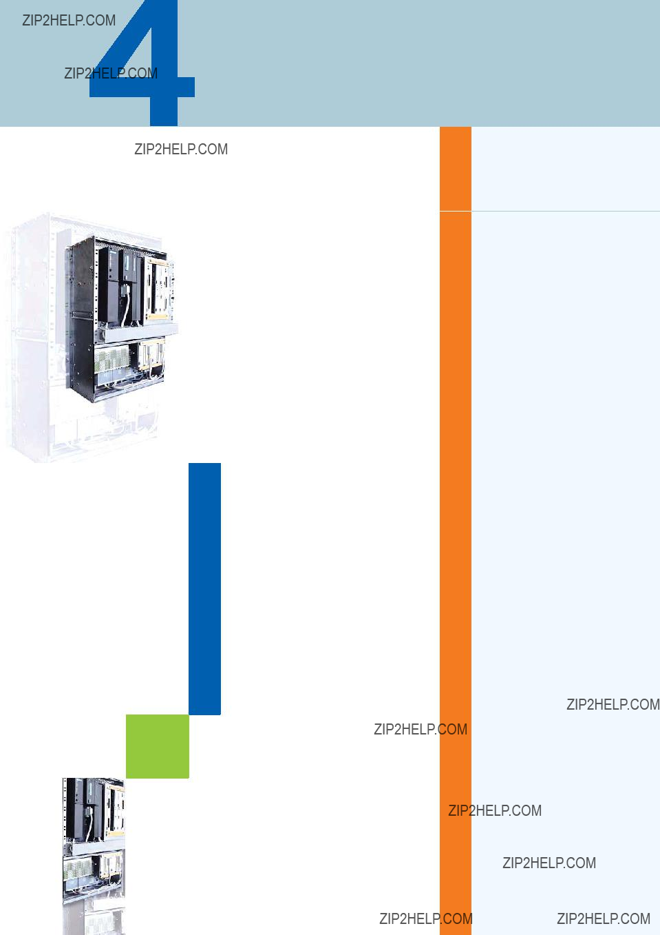
AS 488 K compact system
???Overview
???Ordering Data
Order No.
The AS 488 K compact system is a design version of the
AS 488/TM automation system which is compatible with the pre- vious AS 235 K system. With this design version, the AS 488/TM is integrated in a MIG K compact migration rack corresponding to the compact rack of the AS 235 K. The MIG K migration rack is shielded by a metal plate at the rear, and can be fitted in a TELEPERM M wall housing (mounted at rear) or in 19" cabinets (mounted on front members). It provides five slots for TELEPERM M I/O modules, three of which are assigned to
I/O bus A and two to I/O bus B. A line with up to four ES 100 K extension systems can be operated on each of these I/O buses via serial interface modules - analogous to the AS 235 K.
In contrast to a system order in the form of individual compo- nents (the orderer is responsible for logistics and assembly), a completely equipped and pretested AS 488 K is ordered using a single Order No. specified by the selection of defined stan- dards. The standards differ with respect to the power supply (DC 24 V or AC 230 V) and the type of CPU (120 MHz or
75 MHz). In addition, supplementary components and parts ??? including any TELEPERM M wall housings or cabinets required ??? can be ordered as individual options.
Please order any TELEPERM M wall housings or cabinets re- quired using Catalog PLT 111. You can download this catalog from the Internet.
Additional information is available in the Internet under:
www.siemens.com/teleperm
Scope of delivery of AS 488 K systems
The complete Order Nos. defined above contain the following components:
Basic system
???SIMATIC M7 CPU
CPU
???SIMATIC M7 CPU
CPU
???Memory modules for CPU
???Expansion and interface modules:
-1 x IF
-1 x IF
Power supply
???AS 488 K systems, DC 24 V or AC 230 V power supply:
-PS 405 load power supply, 10 A
Input: DC 24 V, output: DC 24 V/DC 5 V, 10 A, width: 2 standard slots
-2 backup batteries type AA; 3.6 V; 1.9 Ah (for buffering of time)
???AS 488 K system, AC 230 V power supply:
plus integral PS SITOP POWER load power supply, 24 V/10 A as standard
Input: AC 230 V, output: DC 24 V, 10 A
Packaging system/migration racks
???MIG K compact migration rack for AS 488 K (design alternative 1)
-With integral UR2 rack, 5 slots for TELEPERM M I/O modules
-With integral AC 230 V/DC 24 V power supply, 6EP1
???MIG K compact migration rack for AS 488 K (design alternative 2)
-With integral UR2 rack, 5 slots for TELEPERM M I/O modules
-With DC 24 V power supply

This catalog is out of date, see note on page 3
TELEPERM M I/Os connection
???Connection of TELEPERM M AS I/Os to 488 K, comprising:
-TPM
-TBX 478 interface module, for connection of TELEPERM M I/O buses
-Set of ribbon cables for I/O buses with 3 or 2 slots
Connection to CS 275 system bus
???TPM
???CS 275 compact cable
for connection of AS 488 K to the integral local bus island with redundant CS 275; preassembled, two UI connectors
Note: further CS 275 bus components such as bus converters UI, remote bus connection board AF etc. are not part of the de- livery (can be ordered as options).
System software
???AS 488/TM system software, comprising:
-Function blocks, TML and STEP M on memory card, storage capacity 8 Mbyte (user memory 4 Mbyte)
-Commissioning terminal software for PC/programming de- vice on 3.5" diskette (DOS and NT versions)
Compact system
AS 488 K
AS 488 K compact system
Accessories
This catalog is out of date, see note on page 3
Compact system
AS 488 K
AS 488 K compact system
Accessories
Bus components for single CS 275
???Bus converter UI with coaxial cable
???Connection board AF with termi- nating resistor (required for UI)
These components are not included in the scope of delivery of the AS 488 K. They are usually already present when migrating.
Bus components for redundant CS 275
???Bus converter UI with coaxial cable
???Connector board AF with termi- nating resistor
(required for UI)
These components are not included in the scope of delivery of the AS 488 K. They are usually already present when migrating.
AS cables for
Connection distributor for
Packaging system
TELEPERM M 19" cabinets and TELEPERM M wall housing
1 x each
6DS4
6DS9
2 x each
6DS4
6DS9
See Section "Bus communica- tion" - "CS 275" and Catalog PLT 130
6DS9
See Catalog PLT 111
This catalog is out of date, see note on page 3
AS 488 in SIMATIC design
Siemens PLT 112 ?? 2002
This catalog is out of date, see note on page 3
AS 488 in SIMATIC design
Introduction
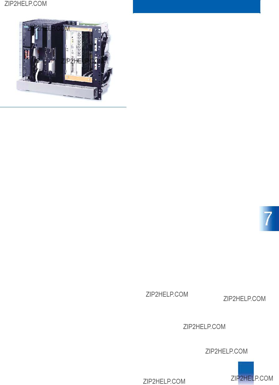
AS 488/TM
???Overview
The AS 488 automation system comprises:
???CPU
???DC 24 V power supply (standard); a module for AC 120/230 V can be inserted as an option (the AC 120/230 V power supply is only possible if no TELEPERM M I/O modules are used)
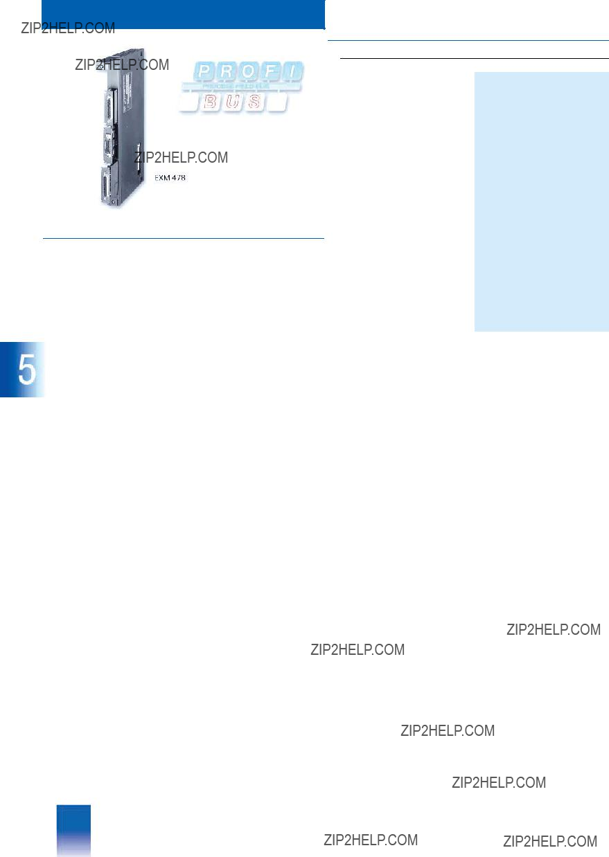
???One or two EXM 478 extension modules (depending on system design and configuration) with IF
???TPM 478 as additional option in conjunction with a further TBX 478 module, located between the DC 24 V power supply module and the CPU, for connection of up to seven I/O units with I/O modules of the TELEPERM M process control system
???As an alternative to the
???Technical Specifications
System configuration
This catalog is out of date, see note on page 3
Coupling to other systems with
DP interface
AS 488 in SIMATIC design
Ambient conditions
1) Required special drivers on request from Roland.Heid@siemens.com, Tel. +49 721
All modules configurable with COM PROFIBUS can be connect- ed via
Further requirement:
The data interface of a station on the
SupportLine,
Tel. +49 180 5050 222,
Fax +49 180 5050 223,
This catalog is out of date, see note on page 3
AS 488 in SIMATIC design
Central processing unit
???Overview
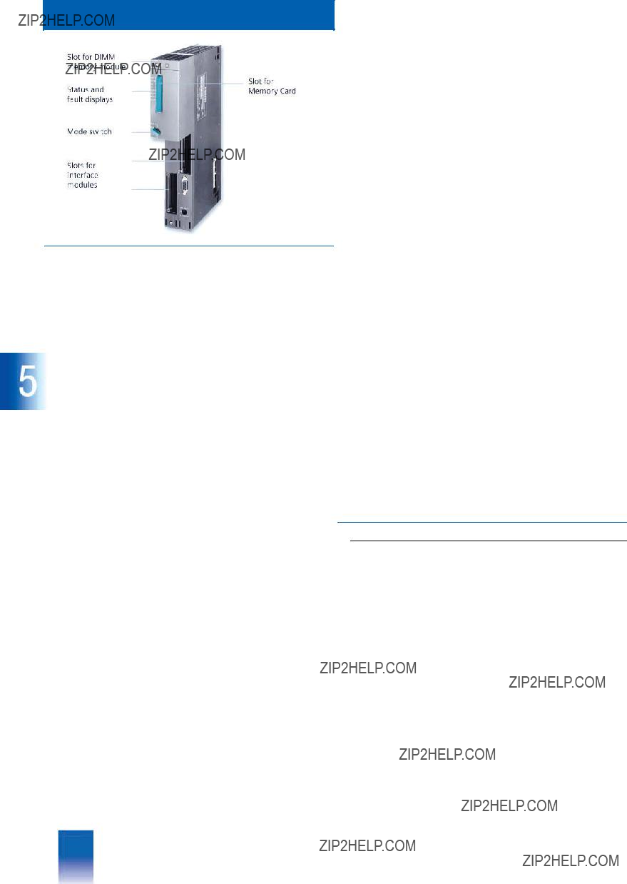
CPU
The CPU
The front of the robust, compact plastic housing contains:
???LEDs for status and fault displays
???Mode switch
???Slot for a memory card from which the system and application software is loaded into the main memory during startup
???2 slots for interface modules.
I & C monitoring
The IF
???Door contact
???Overtemperature
???Monitoring of optical link module OLM
or to trigger a cabinet lamp or horn.
Line monitoring, e.g. to detect an
The inputs and outputs have an electrically isolated design. The module electronics (ASIC) is protected against overvoltages by appropriate measures on the circuit.
The digital inputs comprise 8 channels arranged in groups of 4 x 2 channels. The current consumption is 8.4 mA with an input level of DC 24 V.
An input delay of 500 ??s or 3 ms can be parameterized for all in- put channels together.
Possible cable lengths:
???Unscreened 200 m (with 500 ??s) or 600 m (with 3 ms)
???Screened 1000 m.
The digital outputs also comprise 2 x 4 channels. The max. out- put current is 100 mA with DC 24 V. The outputs are protected against
A
The CPU
The front of the robust, compact plastic housing contains:
???LEDs for status and fault displays
???Mode switch
???Slot for a memory card from which the system and application software is loaded into the main memory during startup
???2 slots for interface modules.
Memory module (set with 2 x 8 Mbyte)
The CPUs
The IF
???Ordering Data

This catalog is out of date, see note on page 3
AS 488 in SIMATIC design
Power supply modules
???Overview
PS 405 and PS 407 load power supplies
The modules of the AS 488/TM automation system are provided with the DC 5 V and DC 24 V operating voltages from the PS 405 and PS 407 power supply modules via the backplane bus.
A PS 407 power supply module (for AC 120/230 V; only for oper- ation without TELEPERM M I/O modules) or a PS 405 power sup- ply module (for DC 24 V) is required depending on the input volt- age.
The power supply module is inserted on the left in the rack. It is fitted in a casing and is cooled by natural convection. The front of the module contains:
???LEDs for display of correct output voltages, correct backup battery voltage and internal faults
???Button for acknowledgment of faults
???On/off switch for output voltages
???Battery compartment (hidden) for backup battery
???Switch (hidden) for activation of battery monitoring
???Mains voltage selector (hidden) for AC 120/230 V
???Mains connection (hidden) with
The DC 24 V load power supplies are each available in
The AC 120/230 V load power supply must not be used together with TELEPERM M I/O modules.
Backup battery
A backup battery is additionally required for the AS 488/TM au- tomation system. The PS 405 and PS 407 load power supplies are fitted with a battery compartment. If the power supply fails, the time and date in the CPU are buffered.
???Ordering Data
This catalog is out of date, see note on page 3
AS 488 in SIMATIC design
Connection of distributed I/Os
???Overview
All versions of the AS 488/TM automation system can be operat- ed with distributed process I/Os on the
In addition to the ET 200 M I/O devices specially tailored for pro- cess engineering with a wide selection of signal and function modules from the SIMATIC
ET 200X or ET 200U (no longer actively marketed) systems as process I/Os on
Up to 122 stations can be connected via each of the two physi- cally isolated lines of the
Each of the two
AS 488/TM via an IF
The second
???Ordering Data
to accommodate 3 interface mod- ules
Required 1 x for each of the max. 2 DP lines with electrical version of

This catalog is out of date, see note on page 3
AS 488 in SIMATIC design
Connection to TELEPERM M I/Os
???Ordering Data
???Overview
Together with the TPM 478 interface module, the TBX 478 inter- face module connects the I/O modules of the TELEPERM M pro- cess control system to the AS 488/TM system.
The following interfaces are present on the TBX 478 module:
???Interface to TPM 478 module for implementation of the two TELEPERM M I/O buses A and B
???Two interfaces connected via cables to the rear of the migra- tion rack for connection of the I/Os in the basic cabinet
(I/O bus A) and extension cabinet (I/O bus B), with use of the I/O slots of the MIG II migration rack
???Interface for "+5 V bus" for supply of the TELEPERM M exten- sion units (cabinet connections)
???Interface to backplane bus for supply of "+5 V bus" from the power supply module of the automation system.
The TBX 478 module need not be parameterized. It is provided with data from the TPM 478 module.
The configuration parameters for the I/O area are defined by the PROGRAF AS+/NT configuring tool and the SYST.WART mainte- nance block and subsequently saved permanently on the mem- ory card by archiving. The new or modified parameters are acti- vated during the next restart.
The TPM 478 interface module is not only required for connec- tion of the TELEPERM M I/Os to the AS 488/TM, but also for con- nection of the AS 488/TM and the

This catalog is out of date, see note on page 3
AS 488 in SIMATIC design
Connection to CS 275
Connection to
???Overview
The AS 488/TM and the
???CS 275 functionality
A powerful CPU processes the communications functions to the CS 275 bus system. The functionality of the TPM 478 inter- face module corresponds to the functionality of the standard N- AS local bus interface module in the AS 235 automation sys- tem. Exception: CD operation is not supported.
Note:
An AS 488/TM automation system can only be connected to one of the two
???Overview
See Section "Process I/Os" for components for connection of dis- tributed process I/Os such as the IF
See Section "Bus communication" for components for connec- tion of the CS 275 and
See Sections "Coupling of systems" and "Bus communication" for components for connection of the
???Ordering Data
Order No.
???TELEPERM I/O functionality
In the AS 488/TM automation system, the TPM 478 module to- gether with the TBX 478 module also provides the interfacing for the TELEPERM M I/Os. The two modules provide two I/O bus interfaces for TELEPERM M basic and extension cabinets, and supply the I/O bus logic with +5 V bus.
Only one TPM 478 module is required for both the CS 275 and TELEPERM M functionalities.
???Ordering Data
for connection to CS 275 and for TELEPERM M I/Os
With electrical version of
to accommodate 3 interface mod- ules

This catalog is out of date, see note on page 3
AS 488 in SIMATIC design
Packaging system
???Overview
UR2 rack
The UR2 universal rack is the mechanical support for the AS 488 automation system. It accommodates the system modules (CPU, load power supply, EXM 478, TPM 478 and TBX 478), provides the modules with operating voltages, and links the in- dividual modules via the backplane bus.
The rack comprises:
???Aluminium support rails with threaded bolts for securing the modules, and
???Plastic parts as guide when swinging in the modules
???Connection for protective earth conductor
???Backplane bus with plug connectors.
Migration rack
An AS 488/TM system can be installed in an existing TELEPERM M cabinet by using an MIG I or MIG II migration rack.
The MIG I migration rack (simple version) is designed using 19" technology and equipped with the SIMATIC
The MIG II migration rack (extended version) is also designed using 19" technology, and integrates the AS 488/TM system modules in the same manner as the MIG I migration rack. It ad- ditionally contains 5 slots for I/O modules which can be option- ally set for slot addressing. As with the AS 235, these I/O slots are wired using
The ability to accommodate up to 5 I/O modules and to set slot addressing for these modules means that the MIG II migration subrack is the first choice for migration of TELEPERM M automa- tion systems.
???Ordering Data
This catalog is out of date, see note on page 3
AS 488 in SIMATIC design
For operation as well as loading and archiving of the system and user functions, the CPU provides an interface for a memory card in addition to the integral main memory (RAM).
The
The memory card with the AS 488/TM system software and the commissioning terminal software are combined in one ordering unit.
The commissioning terminal can be used to download initializa- tion and driver software to the memory card, e.g. for a second
IP 262 in ET 200U.
The system documentation of the AS 488/TM comprises the de- scription "AS 235 automation system, software version G" and the manual "Supplementary system documentation for
AS 388/TM, AS 488/TM and
Important supplementary information in German is present in Microsoft Word format on the diskette with the "Commissioning terminal software for PC/programming device". In English, these supplementary documents are available as "AS
???Ordering Data
Order No.
Manual
Supplementary system documen- tation for AS 388/TM, AS 488/TM and
Additional configuring tools
???PROGRAF AS+/NT for AS 488/TM: see Section "System architecture"
???COM PROFIBUS for
???Ordering Data
comprising:
???Function blocks, TML and STEP M, on memory card, 8 Mbyte
???Commissioning terminal soft- ware for PC/programming de- vice, on
Upgrade/update, as system soft- ware, for upgrading to M02, update and for restoration
This catalog is out of date, see note on page 3
SIMATIC PCS 7 cabinet design
Siemens PLT 112 ?? 2002
This catalog is out of date, see note on page 3
SIMATIC PCS 7 cabinet design
Introduction
Cabinet packaging system
???Overview
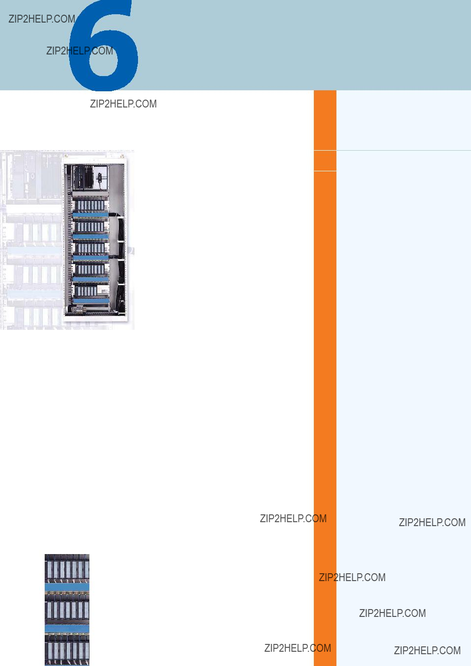
The cabinet design for components close to the process (auto- mation systems and I/Os) fulfills the technical and economical demands placed on the AS 488/TM automation systems.
The cabinets consisting of
As a result of their variable modular design, the cabinets can be readily adapted to different types of system (for batch processes or continuous processes) and system sizes.
The Siemens standard cabinet 8MC with degree of protection IP 40 is the preferred basic cabinet. Cabinets with degree of protection IP 20 and IP 55 are alternatively available.
Modular design
???AS 488/TM system unit
???ET 200M I/O unit (ET 200U/ET 200B on request)
???Basic cabinet, consisting of framework, door, outer walls, inter- nal mechanical parts and power supply assembly with:
-Compartment for documents
-Trim
-AC 230 V socket
-AC 230 V or DC 24 V cabinet illumination
-I & C monitoring via automation system or cabinet lamp
Options
???
???I/O modules for ET 200M I/O unit
High flexibility
???Future compatibility as result of universal,
???Modular packaging system permits flexible adaptation to the respective application
???Basic and expansion cabinets based on the same set of mod- ules
???Up to 4 system units or 6 I/O units can be fitted in a cabinet
???System units and I/O units can be combined within the cabinet
???Side walls or partitions can be selected specific to the applica- tion
???Cabinets can be screwed together into double units or rows
???Design supports installation, commissioning, servicing and re- pairs
???Design supports correct handling when replacing modules
???All installation, commissioning, servicing and repair work can be carried out from the front of the cabinet
???Design of power supply assembly: either with Siemens circuit- breakers or with
???Wiring for electronics supply as well as load power supply to I/O modules
???Wiring of
Consideration of
???The construction of the system and I/O units permits a cabinet design which satisfies the
???Uniform installation and replacement for all I/O modules from the ET 200M range, including Ex(i) modules (plug connection for load power supply above the modules).
Design guidelines
???The SIMATIC
Preparation of quotation, consulting and ordering
???Siemens AG
Tel.: +49 721
Fax: +49 721
This catalog is out of date, see note on page 3
SIMATIC PCS 7 cabinet design
Basic cabinet
???Overview
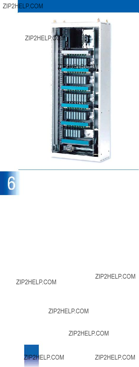
The Siemens standard cabinet 8MC is the preferred basic cabi- net. The Siemens standard cabinet 8MC is a
Side walls and partitions are optional, thus permitting variable adaptation of the cabinet to different installation possibilities.
Up to four system units or six I/O units can be fitted in a cabinet in conjunction with a DC 24 V or AC 230 V power supply assem- bly. System and I/O units can also be combined together within a cabinet. The cables are introduced into the cabinet from be- low.
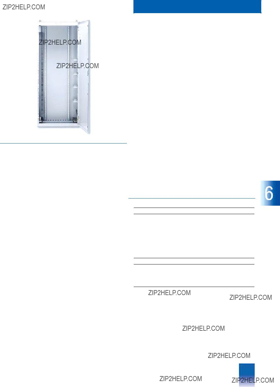
Mechanical design
Each delivered cabinet contains:
???
???Rear panel
???Door
???Transport lugs
Electrical design
Each delivered cabinet contains:
???Power supply assembly AC 230 V or DC 24 V
???Cable clamps and screen bars for I/O and bus cables
???Prewiring of power supply cables for central and I/O units
???Wiring of
???Connector board for cabinet earth
Options for the electrical design
???AC 230 V socket (installed in power supply assembly)
???I & C monitoring (2 versions):
-I & C monitoring via cabinet lamp. A blown fuse is signalled by a lamp in the cabinet door. OLM failure can be additionally displayed on the cabinet lamp
or
-I & C monitoring via AS 488/TM and cabinet lamp. Tempera- ture violations in the cabinet, an open door contact, a blown fuse and an OLM failure can be recorded by the IF
-Single/redundant design of power supply assembly, option- ally with 6 or 14
???Cabinet illumination
Preparation of quotation, consulting and ordering
Siemens AG
Tel.: +49 721
Fax: +49 721
???Technical Specifications
Siemens standard cabinet
??? Cable duct for
Options for the mechanical design
When ordering the basic cabinet, the following options are avail- able for the mechanical design of the cabinet:
including rod lock with 3 mm lock insert and
DIN 43 668
???Plinth: a cabinet plinth should be used if cables cannot be con- nected through the floor. The plinths are preassembled, and available with a height of 100 or 200 mm
???Pocket for documents
???Trim
???Side walls/partitions: the basic cabinets are suitable for individ- ual assembly or in rows. Therefore side walls and/or partitions can be selected when ordering.
This catalog is out of date, see note on page 3
SIMATIC PCS 7 cabinet design
ET 200M I/O unit
???Overview
Complete ET 200M I/O stations are available for the cabinet packaging system. The station includes the power supply, com- ponents for connection to the
The modular ET 200M I/O station with degree of protection IP 20 can be equipped with signal and function modules from the SI- MATIC
Power supply
The ET 200M I/O station can be operated with DC 24 V or
AC 120/230 V. With a DC 24 V supply, the I/O station is powered directly from the cabinet???s power supply assembly, with an
AC 120/230 V supply, a PS 307 power supply module is addi- tionally required upstream of the IM 153 interface module in the I/O station in order to convert the AC 120/230 V into DC 24 V. The DC 24 V input voltage provided by the power supply assembly or the PS 307 power supply module is used to power the IM 153 and is the load power supply for the I/O modules.
The PS 307 power supply module is available in 5 A and 10 A versions. The PS
I/O modules results in a higher load, it is recommendable to use the PS
One fuse is fitted in the power supply assembly for each I/O sta- tion. With a DC 24 V supply, the IM 153 module and the L+/M- power supply for I/O modules are fused together.
With an AC 120/230 V supply, the PS 307 power supply module is fused. The L+/M voltage for the I/O modules is also obtained from the PS 307.
Hot swapping
When ordering an ET 200M I/O station, it is additionally possible to order the hot swapping function.
In an I & C system, it may be necessary to replace modules dur- ing operation for reasons of increased availability. The I/O sub- system for hot swapping is available for this as a version of the ET 200M. This version permits replacement of modules without having to switch off the associated ET 200M subsystem. The functions of the inserted modules are not affected. The hot swapping subsystem consists of backplane modules which can be assembled to form a backplane of the required length, and a matching mounting rail.
Special bus modules are required for the hot swapping function. In addition to the PS/IM bus module for the IM
Ex(i) design
The cable duct with the Ex(i) version is designed as standard in blue. Ex process cables are routed separately from other cables in the cable duct. Furthermore, a mechanical separation is re- quired between the IM 153 module and the first Ex I/O module. An Ex partition is fitted for the hot swapping function to guaran- tee the specified insulation distance between
The DM 370 spacer module is used for this purpose if the hot swapping function is not required.
Load power supply for I/O modules
The load power supply for the I/O modules is connected via plugs located above the I/O modules. One plug is provided for each I/O module. The load power supplies are available in ver- sions for four or eight I/O modules. With fewer than four or eight I/O modules, the unused plug connectors are supplied sepa- rately should subsequent installation of I/O modules become necessary.
Preparation of quotation, consulting and ordering
Siemens AG
Tel.: +49 721
Fax: +49 721
This catalog is out of date, see note on page 3
SIMATIC PCS 7 cabinet design
???Overview
The scope of delivery of the AS 488/TM is variable, and is de- fined specific to the order.
Fundamental components of the AS 488/TM are:
???Mounting board for the UR2 rack and the rail for the OLM opti- cal link module
???AS 488/TM CPU, comprising:
-SIMATIC M7 CPU
-Memory module set with 2 x 8 Mbyte
-UR2 rack (9 slots)
-IF
-IF
-AS 488/TM system software on
-Commissioning terminal software on
???
???Components for connection to the CS 275 or
AS 488/TM system unit
???DC 24 V or AC 120/230 V power supply: depending on the in- put voltage, the AS 488/TM can be equipped either with a
PS 407 power supply module (AC 120/230 V supply) or a
PS 405 power supply module (DC 24 V supply), each rated at 10 A. These supply the AS 488/TM modules with the DC 5 V and DC 24 V operating voltages via the backplane bus. The PS 405 and PS 407 power supply modules also contain the backup batteries for buffering the time and date.
???Supplementary system documentation consisting of a manual for AS 388/TM, AS 488/TM and
Preparation of quotation, consulting and ordering
Siemens AG
Tel.: +49 721
Fax: +49 721

This catalog is out of date, see note on page 3
SIMATIC PCS 7 cabinet design

This catalog is out of date, see note on page 3
Migration of existing systems
Siemens PLT 112 ?? 2002

This catalog is out of date, see note on page 3
Migration of existing systems
Introduction
Migration of existing systems
???Overview
Two different design versions of the AS 488/TM migration packages are available for migrating existing TELEPERM M AS 220 S, AS 230, AS 230 K, AS 235 and AS 235 K automation systems: AS 488 S and AS 488 K.
Migration of the AS 220 H and AS 235 H automation systems is only possible specific to projects, with relinquishing of redun- dancy
The AS 488 S migration package for migrating AS 220 S/H, AS 230/ AS 230 K or AS 235/ AS 235 K/ AS 235 H with
AS 488/TM in cabinet packaging system and the AS 488 K mi- gration package for migrating AS 230 K/ AS 235 K with
AS 488/TM in compact design guarantee, on the one hand, maintenance compatibility of existing plants with systems which have already been deleted or will soon no longer be available, and, on the other hand, offer numerous facilities for modernizing and expanding these plants with a simultaneous increase in AS performance.
The application software has compatible functions, and can be used further providing it is generated and used in line with the standards described in the manuals. This also applies to all downloadable special drivers of standard I/O modules which have been explicitly released for AS 488/TM.
AS 488 S or AS 488 K automation systems for new plants or for the expansion of existing plants can be defined using an Order No. with associated configurator, and are then supplied completely equipped and pretested.
On the other hand, when migrating existing systems with
AS 488 S or AS 488 K migration packages, it is necessary to ex- amine the specifications of the output systems, the local condi- tions, and further
Special ordering and handling procedures therefore apply to the AS 488 S and AS 488 K migration packages.
The AS 488 S/AS 488 K migration packages have a fixed, de- fined scope of delivery and performance with alternatives with respect to the CPU performance (75 MHz or 120 MHz) and the type of migration rack (with or without slots for TELEPERM M I/O modules for AS 488 S or with a DC 24 V or AC 230 V supply for AS 488 K). This means that only TELEPERM M I/Os can be used. Previous experience has shown that migration solutions are usually extremely specific, and deviate from the standard scope of the AS 488 S and AS 488 K migration packages. Com- ponents or system extensions, e.g. with distributed I/Os on the
AS 488 S cabinet system or AS 488 K compact system) or can be the content of individual additional agreements with additive services. Additional agreements always require an individual quotation. In order to simplify the production of quotations, and to improve the cost transparency, special performance packag- es have been defined for frequently requested additional services.
???Configuration
General marginal conditions
During migration of AS 220 S, AS 230 and AS 235 automation systems to AS 488/TM, the subrack with the central modules in the TELEPERM M cabinet is replaced by an AS 488 S with com- patible functions based on the MIG I or MIG II migration rack. The AS 230 K and AS 235 K compact automation systems can also be directly migrated using the AS 488 K of identical pack- aging design. During this, the complete basic system including the power supply and the slots for connection to the CS 275 are replaced by an AS 488 K with compatible functions based on the MIG K migration rack.
Existing AS extension units (max. 7) or ES 100 K extension sys- tems (max. 8) with I/O modules of the TELEPERM M process control system, including any subordinate SIMATIC S5 I/Os, can be connected to an AS 488/TM. With mixed configurations con- sisting of extension units and systems, max. 8 (2 x 4) extension units/ES 100 K extension systems are permissible per
AS 488/TM.
The following assignments are possible per I/O bus:
???3 extension units and one ES 100 K extension system
???At least 1 extension unit and up to three ES 100 K extension systems
???Up to 3 extension units in the basic cabinet, or up to
4 extension units in the extension cabinet of an AS 230 or
AS 235 system. The ribbon cable must be replaced when us- ing 3 or 4 extension units for AS 230.
Field multiplexers and FM driver blocks (together with links) can- not be used.
When using the MIG I migration rack, the I/O modules inserted in the basic unit of an AS 220 S, AS 230 K or AS 235 K automa- tion system must be converted into extension units/systems, or they are omitted. Up to 5 I/O modules can be transferred to a MIG II or MIG K migration rack if the process signal cables are reconnected.
The AS 220 H and AS 235 H automation systems can only be in- corporated into the migration with relinquishing of redundancy.
The conversion is carried out specific to the project by replacing the AS 220 H basic unit (without EE1 extension unit) or the
AS 235 H basic unit by an AS 488 S with additional adaptation to the redundant solution. In the case of the AS 235 H, technical clarification is necessary because of the different I/O conditions; these are not covered by a standard conversion.
The AS 488/TM has no local terminal for direct operation and monitoring or for configuring. Operation and monitoring func- tions comparable with the local terminal of the AS 235 are pro- vided by the PROGRAF AS+/NT configuring tool when connecting via the CS 275 system bus. A further alternative is the use of
The conversion of the application software from a source AS into a target AS is carried out 1:1. The standard service does not in- clude testing for any special drivers which may be present, sub- sequently loaded structures which are incompatible (system blocks in the RAM), or overload configurations.
The application structure must be provided on diskette to enable software conversion.
This catalog is out of date, see note on page 3
???Overview
The AS 488 S migration package is an optimized,
AS 230 K and AS 235/AS 235 K automation systems (AS 220 H and AS 235 H with limitations) with AS 488/TM in cabinet pack- aging system.
Scope of delivery and services
The scope of delivery and services of the AS 488 S migration package is defined as follows:
???AS 488 S automation system (cabinet system) incl. system soft- ware
???Standard conversion service
???Conversion of AS 220 S/H into AS 488 S???
-Removal of subrack with the AS 220 S/H basic unit
-Installation of AS 488 S in the associated system cabinet, connection and commissioning
-Conversion, transfer and adaptation of the application soft- ware on the basis of the standard blocks, without testing of software functions
???or standard conversion service ???Conversion of AS 230/ AS 230 K or AS 235/ AS 235 K into AS 488 S???
-Removal of subrack with the AS 230/ AS 230 K or AS 235/ AS 235 K basic unit
-Installation of the AS 488 S in the system cabinet, connection and commissioning (alternate solution required for CS 275 connection when replacing AS 230 K/ AS 235 K in system cabinets)
-Transfer and adaptation of the application software on the ba- sis of the standard blocks, without testing of software func- tions The application software ??? providing it corresponds to the standards described in the manuals ??? has compatible functions and can be used further.
Migration of existing systems
Migration packages
AS 488 S migration package
Additive supplementary components and services
Previous experience has shown that migration solutions are usu- ally extremely specific, and deviate from the standard scope of the AS 488 S migration packages. Components or system ex- pansions, e.g. with distributed I/Os on the
???Conversion of I/O modules (max. 5) from the basic unit/system of AS 220 S/ AS 230 K/ AS 235/ AS 235 K into the MIG II migra- tion rack and rewiring of the associated process signal cables
???Reconfiguring of CD into DI couplings
???Structure analysis of application for illegal blocks or structure faults
???Documentation of the AS 23x application software according to the block sequence (following XB) with help of
PROGRAF AS/AS+
???Hardware adaptation/conversion resulting from elimination of redundancy when converting AS 220 H/ AS 235 H systems
???Extended configuring (SYST.WART) with connection of ET 100 or S5 I/Os
???Configuration and activation of the AG/AG coupling (additional hardware required)
???Configuration and activation of the MODBUS coupling (addi- tional hardware required)
???Basic installation of
???Reconfiguration and adaptation of an existing
The necessity for packages for supplementary services may re- sult in one or all three phases of the migration process:
???Phase 1: production of quotation
???Phase 2: data conversion
???Phase 3: commissioning on site
Since it is necessary to recognize the supplementary services packages early to permit high planning accuracy, the informa- tion required for the analysis (see checklist for migration) must be available early enough.
Production of quotation and ordering
Siemens AG
Tel.: +49 721
Fax: +49 721
This catalog is out of date, see note on page 3
Migration of existing systems
Migration packages
AS 488 S migration package
???Configuration
General marginal conditions/limitations
The conversion of an AS 220 S/AS 230/AS 235 into an AS 488 S is carried out 1:1, i.e. the respective basic unit in the existing TELEPERM M cabinet (without I/O modules for AS 220 S and AS 235, or without extension unit EE1 for AS 230) is replaced by a migration rack with the AS 488 S with compatible functions. Expansions or extensions carried out simultaneously, as well as modifications and adaptations which do not belong to the stan- dard scope of the conversion services, e.g. the new wiring of I/O modules inserted in a basic unit GE, will be charged separately.
Existing TELEPERM M extension units EE (max. 7) or ES 100 K extension systems (max. 8) can be connected to the AS 488 S. In the case of mixed configurations of extension units and exten- sion systems, max. 8 (2 x 4) EE/ES 100 K are permissible per AS 488 S. The following assignments are possible per I/O bus:
???Three extension units and one ES 100 K extension system
???At least one extension unit and up to three ES 100 K extension systems
???Up to 3 extension units in the basic cabinet, or up to four exten- sion units in the extension cabinet of an AS 230 or AS 235 sys- tem. The ribbon cable must be replaced when using 3 or
4 extension units for AS 230.
???Ordering Data
The migration of existing automation systems using AS 488 S mi- gration packages is a complex process comprising a quotation and ordering phase with detailed clarification based on a check- list, the data conversion phase, delivery and commissioning on site, and the return of licensed components. The planning and coordination of such a migration requires intensive contact as well as exact arrangements and agreements between all in- volved parties.
The following information is basically required for ordering AS 488 S migration packages by DP system or fax:
???Order No. and quantity of migration packages including de- tailed information on the migration rack (MIG I or MIG II) and on the CPU (CPU
???Type of AS 220, AS 230 or AS 235 automation system to be mi- grated in each case
???Quantity and length of connecting cables 6DS8
???Dates for conversion and commissioning work on site
???Quantity and language of AS 235 system software description and of supplementary system documentation for AS 488/TM.
Only those TELEPERM M/ME I/O modules listed in Catalog PLT 112 and published on the TELEPERM M site on the Internet (including any subordinate SIMATIC S5 I/Os from Catalog
PLT 111) can be used in the extension units/systems. Please ob- serve the limitations!
Additional information is available in the Internet under:
http://pcs.khe.siemens.de/index.asp?Nr=2644
Two versions of the migration rack are available for conversion to AS 488 S. Migration rack II, Order No. 6DS2
The AS 488 S migration rack is available in two CPU versions (75/120 MHz). Thus two performance levels are available.
The replaced basic units or the central components, i.e. the li- censed components of the automation system, must be returned to Siemens AG.
The checklists, ordering forms, addresses for returned goods, and conditions are available on request (see summary on pro- duction of quotations and ordering).

This catalog is out of date, see note on page 3
Migration of existing systems
Migration packages
AS 488 K migration package
???Overview
The AS 488 K migration package is an optimized,
Scope of delivery and services
The scope of delivery and services of the AS 488 K migration package is defined as follows:
???AS 488 K automation system (compact system ) incl. system software
???Standard conversion services:
Service "Conversion of AS 230 K or AS 235 K into AS 488 K"
-Removal of the complete AS 230 K/ AS 235 K basic system
-Installation of AS 488 K in the system housing or system cab- inet, connection and commissioning
-Transfer and adaptation of the application software on the ba- sis of the standard blocks, without testing of software func- tions
Additive supplementary components and services
Previous experience has shown that migration solutions are usu- ally extremely specific, and deviate from the standard scope of the AS 488 K migration packages. Components or system ex- pansions, e.g. with distributed I/Os on the
???Conversion of I/O modules from the basic system of the
AS 230 K (max. 3) or AS 235 K (max. 5) into the MIG K com- pact migration rack and rewiring of the associated process sig- nal cables
???Reconfiguring of CD into DI couplings
???Structure analysis of application for illegal blocks or structure faults
???Configuration and activation of the AG/AG coupling (additional hardware required)
???Configuration and activation of the MODBUS coupling (addi- tional hardware required)
???Basic installation of
???Reconfiguration and adaptation of an existing
The necessity for packages for supplementary services may re- sult in one or all three phases of the migration process:
???Phase 1: production of quotation
???Phase 2: data conversion
???Phase 3: commissioning on site
Since it is necessary to recognize the supplementary services packages early to permit high planning accuracy, the informa- tion required for the analysis (see checklist for migration) must be available early enough.
Production of quotation and ordering
Siemens AG
Tel.: +49 721
Fax: +49 721
???Configuration
General marginal conditions/limitations
The conversion of an AS 230 K/ AS 235 K into an AS 488 K is carried out 1:1, i.e. the existing AS 230 K/AS 235 K basic system is completely replaced in the TELEPERM M housing, rack or cabinet by an AS 488 K with compatible functions. The TELEP- ERM M I/O modules operated in the original systems (max. 3 with AS 230 K or max. 5 with AS 235 K) can be converted be the MIG K migration rack of the AS 488 K. Expansions or extensions carried out simultaneously, as well as modifications and adapta- tions which do not belong to the standard scope of the conver- sion services, e.g. the new wiring of I/O modules, will be charged separately.
The AS 488 K migration package is available with two power supply versions (DC 24 V or AC 230 V) and with two perfor- mances (with
ES 100 K systems can be connected to an AS 488 K just like to an AS 488/TM, existing ES 100 K extension systems can be used further.
Only one migration rack version with 5 I/O slots is available for conversion to AS 488 K. These slots are divided with 3 on the I/O bus A and 2 on the I/O bus B.
Additional information is available in the Internet under:
http://pcs.khe.siemens.de/index.asp?Nr=2644
???Documentation of the AS 23x application software according to the block sequence (following XB) with help of
PROGRAF AS/AS+
???Adaptation of the packaging system required for the
AS 230 K/AS 235 K migration, and conversion of the CS 275 remote bus connection (if present)
???Extended configuring (SYST.WART) with connection of ET 100 or S5 I/Os
The replaced AS 230 K/AS 235 K basic systems with the central components, i.e. the licensed components of the automation system, must be returned to Siemens AG.

This catalog is out of date, see note on page 3
Migration of existing systems
Migration packages
AS 488 K migration package
???Ordering Data
The migration of existing automation systems using AS 488 K migration packages is a complex process comprising a quota- tion and ordering phase with detailed clarification based on a checklist, the data conversion phase, delivery and commission- ing on site, and the return of licensed components. The planning and coordination of such a migration requires intensive contact as well as exact arrangements and agreements between all in- volved parties.
The following information is basically required for ordering AS 488 K migration packages by DP system or fax:
???Order No. and quantity of migration packages including de- tailed information on the power supply (DC 24 V direct or
AC 230 V/ DC 24 V integral) and on the CPU (CPU
???Type of AS 230 K or AS 235 K automation system to be migrat- ed in each case
???Dates for conversion and commissioning work on site
???Quantity and language of AS 235 system software description and of supplementary system documentation for AS 488/TM.
The checklists, ordering forms, addresses for returned goods, and conditions are available on request (see summary on pro- duction of quotations and ordering).
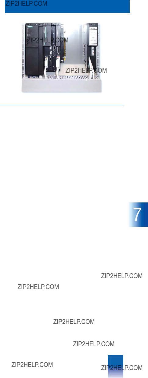
This catalog is out of date, see note on page 3
Migration of existing systems
Migration packages
MIG I migration rack
The migration racks are the core components of the AS 488 S and AS 488 K migration packages. They integrate the
AS 488/TM automation systems as replacements for existing ba- sic units/systems in an existing TELEPERM M system environ- ment.
The following migration racks are available:
???MIG I migration rack
for AS 488 S (without slots for TELEPERM I/O modules)
???MIG II migration rack
for AS 488 S (5 slots for TELEPERM I/O modules)
???MIG K migration rack
for AS 488 K (5 slots for TELEPERM I/O modules)
???Overview
The MIG I migration rack is a subrack of the ES 902 packaging system with assembled SIMATIC
The migration rack has the same dimensions as the basic unit of the automation systems, and replaces this in an AS cabinet. Ex- isting extension systems with installed I/O modules can still be connected to the migration rack and used with it.
The migration rack contains a guide for preassembled cables as well as a fuse for L+ 24 V/16 A.
The MIG I migration rack has no slots for I/O modules. When us- ing this migration rack for conversion of a TELEPERM M automa- tion system into an AS 488/TM, the I/O modules inserted in the AS basic unit must therefore be converted into an extension unit or an additional ES 100 K extension system. A prerequisite, however, is that sufficient slots are still available there for these I/O modules.
2 plugs are located at the rear of the migration rack for connec- tion of the I/O buses A and B using the existing ribbon cables.
In the migration rack, the TPM 478 module processes up to two I/O buses (A and B) with a maximum of 8 extension
units/ES 100 K extension systems via the TBX 478 module.
The following assignments are possible per I/O bus:
??? 3 extension units and one ES 100 K extension system
??? At least 1 extension unit and up to three ES 100 K extension systems
??? Up to 3 extension units in the basic cabinet, or up to four exten- sion units in the extension cabinet of an AS 230 or AS 235 sys- tem. The ribbon cable must be replaced when using 3 or
4 extension units for AS 230.
This catalog is out of date, see note on page 3
Migration of existing systems
Migration packages
MIG II migration rack
???Overview
The MIG II migration rack has been developed further, and is a completely assembled ES 902 subrack for accommodating an AS 488/TM system which can be directly installed in the TELEPERM M standard cabinet instead of an AS 220 S, AS 230 or AS 235 basic unit.
It is designed as a
AS 488/TM system modules (power supply, CPU and interface modules). Compared to the MIG I migration rack, it offers 5 slots for TELEPERM M I/O modules which are fitted on the right side of the rack. When converting, it is therefore possible to transfer 5 I/O modules from the basic unit of the automation system into the migration rack, making it unnecessary to find new slots for these. However, it is necessary to disconnect the process signal cables from the I/O slots, and to reconnect them. To do this, they must be separated between the cabinet connection element SAE and the basic unit. If no SAEs were previously installed for the I/O slot wiring of the basic unit, they must now be inserted in order to also compensate differences in length. The process sig- nal cables are connected at the rear using
Two interface plugs for connection of the two I/O buses A and B are fitted at the rear on the
I/O bus ribbon cables already present in the cabinet are used further. A flexible assignment of the 5 I/O slots to the two
I/O buses A and B is possible.
The previous addresses of the I/O buses can be used further in most cases, especially if slot addressing was not used. Slot ad- dressing is possible for the I/O slots available in the MIG II mi- gration rack, and is essential for certain modules. The slot addresses of the two I/O areas A and B can be selected just like frame addresses by setting jumpers in predefined groups. The settings are made from the front.
The
The interface for I & C messages of the cabinet has been de- signed in the MIG I migration rack as a preassembled cable for connection to the power supply assembly. With the MIG II migra- tion rack, a plug interface with screw terminals has been provid- ed similar to in the AS 235 system.
???Design
Configuration possibilities for I/Os
When migrating an AS 220 S system, the 5 I/O modules of the migration rack can be combined with up to 3 extension units by pressing 2 ribbon cable plugs onto the existing I/O bus cable or by using the additional ribbon cable for 5 slots (see hardware options).
When migrating an AS 230 system, users can freely decide whether the 5 new I/O slots are to be operated together on the I/O bus, i.e. together with up to 3 extension units of the basic cabinet, or divided between the two I/O buses (e.g. 3 on
I/O bus A of the basic cabinet, and 2 on I/O bus B of the exten- sion cabinet). In addition, up to 4 extension units can be con- nected using a new ribbon cable to I/O bus B of the AS 230 system.
As with the AS 230 system, users can also freely decide for the AS 235 system whether all 5 I/O slots in the migration rack are to be operated on I/O bus A, or whether they are to be divided amongst I/O buses A and B. In contrast to the AS 235 system, even 4 extension units can be directly used in the extension cab- inet of the AS 488/TM system. The same technical conditions ap- ply to migration of the AS 235 system as to migration of the
AS 230 system.
The 5 I/O slots in the migration rack are assigned
As with the AS 230 K and AS 235 K systems, this flexible method permits the configuration of two I/O slots for connection of
ES 100 K extension systems (without compact housing).
ES 100 K interface modules 6DS1
ET 200M distributed I/O system (any mixture of 4 on each I/O bus).
This catalog is out of date, see note on page 3
Migration of existing systems
Migration packages
MIG K migration rack
???Technical Specifications
???Overview
The MIG K migration rack has a design equivalent to that of the AS 235 K subrack. It integrates an AS 488/TM, and offers
5 additional slots for TELEPERM M I/O modules.
The MIG K migration rack is already equipped with slots for modules used for connection to the CS 275 system bus.
Two alternatives are available for the power supply. The MIG K can be designed either for direct connection of DC 24 V or with an integral AC 230 V/ DC 24 V power supply.

This catalog is out of date, see note on page 3
Migration of existing systems
Retrofitting services
???Overview
The following contract conditions apply to all services (standard or supplementary services) provided in the context of a migra- tion:
???The services are based on the conditions of the "General instal- lation conditions"
???The application software will be converted 1:1, i.e. from a source AS system into a target AS system in each case, with- out analysis of the functionality of the existing system software
???The work will be carried out within normal working hours (Mon- day to Friday, 9 hours daily)
???The customer must ensure by means of appropriate measures that the wall housing or the front and rear of the AS cabinets or racks are freely accessible for the conversion work
???Travel costs will be charged in addition
???To support smooth conversion, the details resulting from the "Checklist for migration" must be clarified in advance, and the required information provided
???The replaced basic units/systems or the central components, i.e. the licensed components of the automation system, must be returned to Siemens AG.
Conversion, transmission and adaptation of the application soft- ware as well as the conversion measures on site will be carried out by:
Siemens AG, Dept. I&S IS KHE 4,
Tel.: +49 721
Fax: +49 721
This catalog is out of date, see note on page 3
Migration of existing systems
???Overview
Details required for a quotation for migration:
Plant configuration (structure diaphragm)
???OS systems:
-Types, quantity
???Engineering systems:
-Types, quantity, connection
???AS systems:
-Types, quantity
Check list prior to retrofitting
AS configuration for cabinet/compact system for migration with AS 488 S
Basic cabinet/basic system:
???Accessibility of cabinet/system
???Packaging system, special
Extension cabinet/extension systems:
???Accessibility of cabinet/system
???Packaging system, special
???Bus topology (CS 275):
- Bus segments, bus couplers, station addresses
AS configuration for cabinet/compact system for migration with AS 488 S
Basic cabinet/basic system:
???Basic unit
-Central unit type, version
-Types of I/O modules in central unit
-Releases of I/O modules in central unit
-Addressing of I/O modules in central unit
-Process alarm structure
-Coupling interfaces and their drivers
-Special modules, special drivers
???Standard devices
-Local terminals and printers (logs, messages)
Basic and extension cabinet/basic system:
???Extension units/ES 100 K
-Types, quantity
???I/O modules in extension units and ES 100 K
-Types, assignment (configuration)
-Releases
-Addressing
-Coupling interfaces and their drivers
-Special modules, special drivers
AS configuration for compact system for migration with AS 488 K
Basic system:
???Accessibility of housing, rack or cabinet
???Actual packaging system, special
Extension systems:
??? Accessibility of systems and their AS connections
AS user configuration for cabinet/compact system for migration with AS 488 S
???Data medium with current release of application structure (cleared of CD mode and
???System software release and archiving method
???Processing cycle 250 ms or 500 ms (with AS 220 S/H)
???Special software features
-E.g. special drivers, software packages, special interfaces
-Decompilation capability with PROGRAF AS+/NT
AS user configuration for compact system for migration with AS 488 K
???Data medium with current release of application structure (cleared of CD mode and
AS configuration for compact system for migration with AS 488 K
Basic system:
???Basic unit
-Central unit type, version
-Power supply, fusing
-Types of I/O modules in central unit
-Releases of I/O modules in central unit
-Addressing of I/O modules in central unit
-Process alarm structure
-Coupling interfaces and their drivers
-Special modules, special drivers
???Standard devices
-Local terminals and printers (logs, messages)
???ES 100 K extension systems
-Types, quantity
???I/O modules in ES 100 K
-Types, assignment (configuration)
-Releases
-Addressing
-Coupling interfaces and their drivers
-Special modules, special drivers
???System software release and archiving method
???Special software features
-E.g. special drivers, software packages, special interfaces
-Decompilation capability with PROGRAF AS+/NT

This catalog is out of date, see note on page 3
Migration of existing systems
Configuring lists
Migratable TELEPERM M modules in AS 488/TM
Migratable TELEPERM M modules in AS 488/TM
See overleaf for explanations on the table
*) in certain circumstances there are some special features for these modules, please ask your Siemens contact

This catalog is out of date, see note on page 3
*) in certain circumstances there are some special features for these modules, please ask your Siemens contact
Migration of existing systems
Configuring lists
Migratable TELEPERM M modules in AS 488/TM
Explanations for the column ???Remarks???
1)Earlier release versions not permissible!
2)Special product
3)Not a standard product, no system test carried out
5)Application only without interrupt!
6)No application as common alarm module (SF 61)
7)Approved for common alarm modules, the latest product release is required.
8)Note current balance of subrack:
max. 4 A per module, max. 16 A per subrack
9)Combination modules for use in TELEPERM M standard systems and in TELEPERM ME systems. Application in AS 235/488 extension units only as TELEPERM ME module with slot addressing.
11)Note: Release 3 is not allowed!
12)Cycle time in TPM 478 for processing of modules in ES 100 K can be delayed (dependent on the cable length); coupling modules are used at best in the basic unit.
13)Application in ES 100 K not allowed (timing)
14)Connection of transmitters with
15)Module only functions together with 6DS1
16)Only alarm function
17)Module only functions together with 6DS1 713 or 6DS1 731.
19)A maximum of 1 module of type Typ
20)Application in ES 100 K not allowed (5 V power)
21)Hardware/software releases on request: Siemens Karlsruhe,
I&S IT PS KHE3,
22)S7 coupling with 3964 R / RK 512 procedure, SEND/RECEIVE, SIMATIC S5 analog value format
23)only CP 581/TM versions with S5Kx drivers can be used. Power balance of the module can vary up to max. 3 A (with +5 V)
24)cycle time of the process image min. 1 s
Explanations for the column ???Release???
???5 recommended minimum release (for technical reasons). With ear- lier releases it???s possible to have some loss of functions and pro- blems with I/Os; use without guarantee
1; 2; permissible releases
=5 valid release of a module
??? 6 ??? and remark 1) mean an imperative minimum release
(6 in this case), i.e. upgrading is essential at least up to release 6.
Observe the respective indexed remarks for the individual modules.
Observe the details described in the manual ???Supplementary System Documentation AS 388/TM and AS 488/TM??? (Chapter 6).???
This catalog is out of date, see note on page 3
Migration of existing systems
This catalog is out of date, see note on page 3
Process I/Os
Siemens PLT 112 ?? 2002

This catalog is out of date, see note on page 3
Process I/Os
Introduction
???Overview
A wide range of SIMATIC ET 200B, ET 200M, ET 200S, ET 200X and ET 200U 1) distributed I/O systems with a comprehensive selection of I/O modules is available for the AS 488/TM for the acquisition and output of process signals via sensors and actu- ators. The I/O modules of the ET 200M distributed I/O system specially tailored for process engineering are particularly rec- ommendable. The distributed I/O systems are connected to the automation systems via the
976 I/O modules) can be connected per automation system via IF
SIWAREX M function modules of SIMATIC
In addition, a large number of devices possessing a
DP interface can also be operated on the
CPU modules of the SIMATIC
I/O buses of SIMATIC PCS 7,
The migration facilitates with the AS 488/TM automation system also permit existing TELEPERM M I/O modules to be connected via two I/O bus interfaces and used further.
1) ET 200U is no longer actively marketed
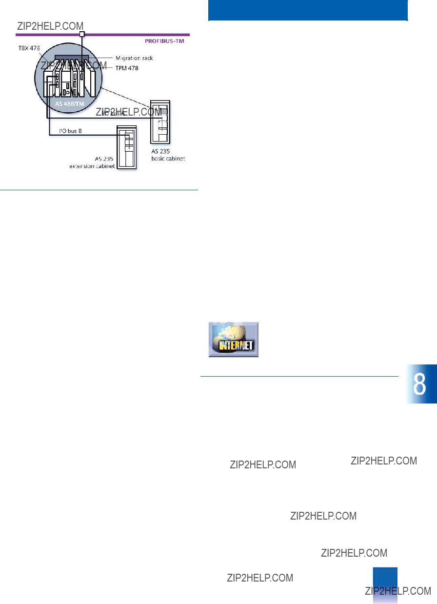
This catalog is out of date, see note on page 3
Process I/Os
Connecting TELEPERM M I/Os
???Overview
In existing TELEPERM M systems, AS 220 S, AS 230, AS 230 K, AS 235 or AS 235 K automation systems are replaced by migra- tion with AS 488 S (cabinet design) or AS 488 K (compact de- sign). System integration is carried out in each case using so- called migration racks (MIG I/MIG II for AS 488 S or MIG K for AS 488 K). The migration rack together with the TPM 478 and TBX 478 interface modules also comprises the interface to the TELEPERM M I/Os in the extension units of the TELEPERM M cabinets and in the ES 100 K extension systems. Data exchange is via the I/O buses A and B of the TBX 478 interface module.
As with the AS 230 / AS 235, up to three expansion units in the basic cabinet as well as an external ES 100 K can be operated on the I/O bus A of an AS 488 S. Following replacement of the ribbon cable for the I/O bus, up to four extension units of an AS 230 / AS 235 extension cabinet can be connected via the I/O bus B. When carrying out migration with AS 488/TM it is therefore possible to add a fourth extension unit to an AS 235 ex- tension cabinet of maximum configuration. There is therefore no limitation with respect to the number of migratable I/O modules for an AS 230 / AS 235 configured with the maximum number of TELEPERM M I/O modules.
The AS 488 K with its MIG K migration rack has a design equiv- alent to that of an AS 235 K. The MIG K migration rack has five slots for TELEPERM M I/O modules. 2 x 4 compact ES 100 K ex- tension systems can be connected via these 5 slots using the serial coupling known from the AS 235 K. These extension sys- tems can be located up to 500 m away from the AS 488 K auto- mation system, and are therefore highly suitable for a distributed design.
The TPM 478 interface module additionally permits connection of an AS 488/TM system to the CS 275 bus system. However, the AS 488/TM automation system must not be connected simulta- neously to the
TBX 478 interface module
The TBX 478 interface module together with the TPM 478 inter- face module links the I/O modules of the TELEPERM M system to the AS 488/TM system.
The following interfaces are present on the TBX 478 module:
???Interface to the TPM 478 module for implementation of the two TELEPERM M I/O buses A and B
???2 remote interfaces connected via cables:
-for connecting the I/Os in the basic cabinet (I/O bus A) and extension cabinet (I/O bus B), with incorporation of the
I/O slots of the MIG II migration rack (cabinet design) or
-for connecting the I/O slots of the MIG K migration rack to I/O bus A and I/O bus B (compact design)
???Interface for "+5 V bus" for power supply to TELEPERM M ex- tension units (cabinet connections)
???Interface to the backplane bus for power supply to the
"+5 V bus" from the power supply module of the automation system.
The TBX 478 module need not be parameterized. It is provided with data from the TPM 478 module.
The configuration parameters for the I/O area are defined using the PROGRAF AS+/NT configuration tool and the SYST.WART maintenance component, and subsequently saved permanently on the memory card. The new or modified parameters are acti- vated when recalled.
Two sets of ribbon cables are available for assigning the 5 I/O slots of the MIG II migration rack to I/O buses A and B. The as- signment of the 5 I/O slots of the MIG K migration rack to
I/O buses A and B is fixed, and cannot be changed.
A list of the TELEPERM M I/O modules which can be operated with the AS 488/TM automation system is available on the Inter- net.
Additional information is available in the Internet under:
www.siemens.com/teleperm
???Ordering Data
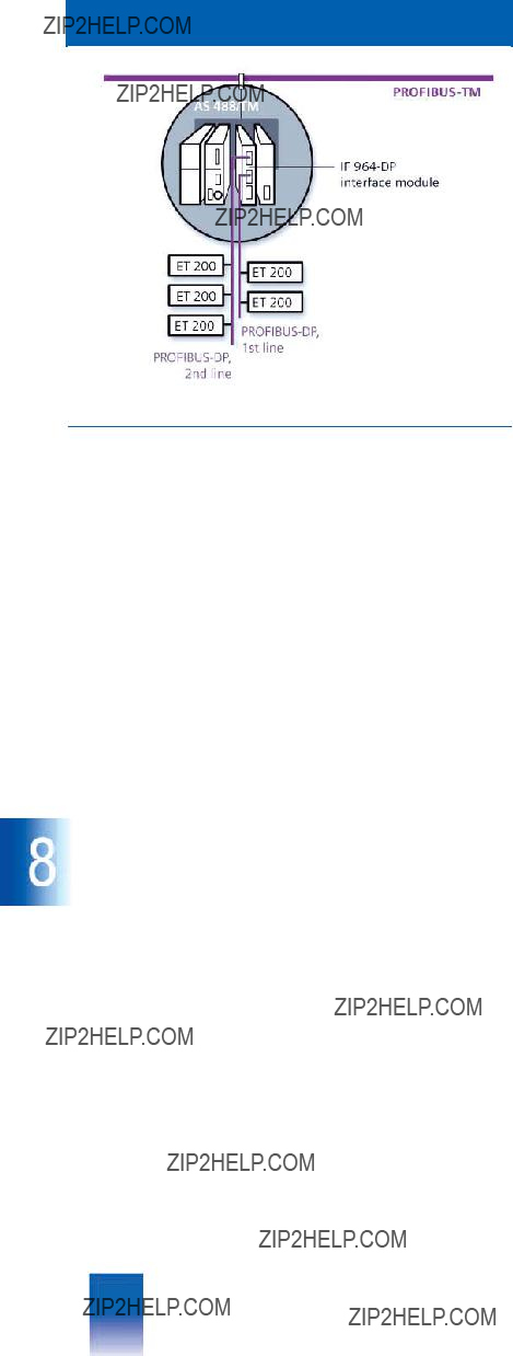
This catalog is out of date, see note on page 3
Process I/Os
Connecting SIMATIC I/Os
???Overview
In addition to the migration of existing TELEPERM M I/Os, all ver- sions of the AS 488/TM automation system can also be extended by distributed I/Os on the
ET 200M system with a comprehensive range of I/O modules es- pecially tailored for process engineering, the SIMATIC ET 200B, ET 200S, ET 200iS (available soon), ET 200X and ET 200U (no longer actively marketed) systems are also suitable.
A comprehensive range of compact modules in casings and for operation without fans is therefore available in the form of mod- ular, distributed units for automation.
The ET 200M I/O system designed for the complex demands of process engineering is suitable for both cabinet and wall mount- ing. The system has a comprehensive range of input/output modules:
???Standard signal modules with
???Standard function modules with autonomous preprocessing, e.g. for dosing and counting
???Ex signal modules for connection of
Two
Interface module for connection to
The IF
Communication via the
The
AS 488/TM automation systems and ET 200 distributed I/O sys- tems, CPUs/CPs with DP interface,
Up to 122 stations can be connected to an automation system via each of the 2 physically isolated lines of the
The second
Bus stations on the DP bus
The AS 488/TM automation system is the DP master and thus the active station in each case. Passive stations (DP slaves) can be:
???ET 200M, ET 200S, ET 200iS (to the extent of a standard slave; available soon), ET 200X, ET 200B and ET 200U distributed I/O systems
???SIMATIC S7 CPU
???SIMATIC
???DP/DP coupler for connecting the
???SIMATIC
???SIMATIC
???
???Field devices (also from other vendors), e.g. drives, valves and process controllers
???SIMATIC
Configuring
The tools available for configuring, parameterization, commis- sioning and diagnostics of the
Process image
The central processing unit of the automation systems commu- nicates with the I/O modules via a process image (current pro- cess data). Module assignments and addresses are defined by the configuration. To achieve this, the associated driver block is parameterized with the module number via the process image in the same manner as for the AS 235 system. SYST.WART is used to assign the module number to the station address.
Network configuration
The possible network configurations of the

This catalog is out of date, see note on page 3
Process I/Os
Connecting SIMATIC I/Os
COM PROFIBUS
COM PROFIBUS is a tool used for fieldbus configuring and for parameterization of the bus stations prior to commissioning. COM PROFIBUS can be installed on the commissioning terminal or on a PC/programming device with Microsoft Windows 95/98/Me/NT/2000.
The tasks of COM PROFIBUS include configuration of the field- bus, generation of the address list, parameterization of slave modules, setting of the transmission rate on the fieldbus, and setting of the failure response.
Slave modules from other vendors can also be parameterized. The vendors usually enclose type/GSD files with their products for linking into the parameterization tools. If these type/GSD files are not available, you can also obtain them using the support services on the Internet sites of the respective vendors or of the PNO (PROFIBUS International). According to EN 50 170, Part 3, these files can also be generated using the master device data if you are sufficiently knowledgeable.
???Technical Specifications
Note:
Max. 7 analog input modules (AI) can be plugged into an
ET 200M because of the consistent data transmission require- ments and the corresponding limit of 122 byte. The 8th module can be a binary input module (BI), a binary output module (BO) or an analog output module (AO).
???Ordering Data

This catalog is out of date, see note on page 3
Process I/Os
DP extensions for AS 488/TM
???Overview
Starting with the AS 488/TM system software M01.00, the ET 200M, ET 200U and ET 200B distributed I/O systems are explicitly released for the AS 488/TM as remote I/Os on the
supported by the DPAE/DPAA and DPBE/DPBE driver blocks right from the beginning. S5 and S7 formats could be used for the raw analog values.
Connection of other standard DP slaves from the product ranges of Siemens and other vendors was assured as far as communi- cation was concerned; however, support with respect to conver- sion of analog values and acquisition of diagnostics data could not be assured in all cases.
The DP extensions for AS 488/TM, which require the AS 488/TM system software M01.06 or M02.00, extend the AS x88/TM by the following functions:
???Support of further DP ranges and devices
-ET 200S, ET 200X
-Links with
-IM
-SIMATIC S7 CPU
???Additional DP4E/DP4A driver blocks with new types of format for analog values
-
-S7/IEEE
(only supported if at least the small
-S5
???HMI driver block with server functions for the TP170B, OP170B, MP270 and MP370 panels based on Microsoft Windows
???Increase in number of DP slaves per DP line to 122
???The user documentation includes information and examples on configuring and diagnostics.
???Mode of operation
Driver blocks
The DP4E/DP4A driver blocks support use of the COUNT mod- ule of ET 200S, amongst others.
The DP4E/DP4A driver blocks directly convert TM
AS 488/TM and the SIMATIC S7 station or the device from anoth- er vendor. Without a
The maximum number of 122 DP slaves on a DP line can only be reached if each DP slave does not occupy more than 64 byte in- put data and 64 byte output data.
???Ordering Data
comprising:
???3.5" program diskettes
-Driver blocks (partially inte- grated in system program, partially downloadable)
-Extension of
-User documentation in Ger- man and English
-Initialization software for oper- ation of the second DP line
???Product documentation in Ger- man and English
Note:
The system software M02.01 or M01.07 already supports the AS 488/TM as standard for the maximum number of 122 DP slaves per DP line as well as hot swapping of ET 200S and ET 200M with IM
The HMI driver block is not suitable for use of panels belonging to the older generation (e.g. OP37). These cannot be directly connected to the DP line of the AS 488/TM via their DP interface, but have to be linked, for example, via an intermediate
The program package "DP exten- sions for ASx88/TM" can be used for AS x88/TM from version M01.06 or M02.00 onwards

This catalog is out of date, see note on page 3
Process I/Os
ET 200M packaging system
ET 200M
The following types of I/O modules can be operated in ET 200M systems on AS 488/TM automation systems:
???Standard
???I & C I/O modules with enhanced diagnostics capability
???Ex input/output modules
DP driver blocks are assigned to the modules when configuring with PROGRAF AS+/NT or ASBEDIEN.
The I & C modules with diagnostics capability offer channel- based fault displays, internal module monitoring, diagnostics alarms, or the freezing of the last value or connection of a default value upon failure of the CPU or the load power supply. They recognize channel faults and
???Overview
The ET 200M modular I/O system with degree of protection IP 20 can be extended by signal modules and function modules of the SIMATIC
The ET 200M is a passive station (slave) on the
IM 153 interface module (IM
???Module faults
???
???Bus faults, i.e. faulty data transmission
???DC 24 V load power supply
???Hot swapping of I/O modules.
Diagnostics data are evaluated decentrally using diagnostics LEDs on the ET 200M, or centrally by means of the CPU in the automation system
The ET 200M can be operated with two types of design:
???Design with bus connectors
???Design with active bus modules (swapping of modules possi- ble during operation).
The ET 200M comprises:
???IM 153 interface module for connection to
A connection to
???Various I/O modules connected by means of bus connectors, or plugged onto active bus modules.
???A power supply if necessary.
The modules are mounted on a DIN rail. The arrangement is set during the hardware configuring with COM PROFIBUS.

This catalog is out of date, see note on page 3
Process I/Os
ET 200M packaging system
???Design
Simple packaging system with bus connectors
The simple packaging system with SIMATIC
???Module installation
Simply hook the modules into the DIN rail, swing into place, and screw tight.
???Integral backplane bus
The backplane bus is integrated into the modules. Bus con- nectors which are plugged into the rear of the housing are used to connect the modules.
The DIN rail is available in various lengths. The
???Ordering Data
Packaging system with active bus modules (with hot swapping function)
If it is necessary to replace modules during operation of a sys- tem for reasons of increased availability, the hot swapping sys- tem is appropriate as an ET 200M version with active bus modules.
This system permits hot swapping of modules without having to switch off the associated ET 200M. The hot swapping system consists of backplane modules from which a backplane of the required length can be produced, and a matching rail. A com- plete system can be ordered for the standard length of
19 inches (482 mm).
Please refer to the individual components listed in the ordering data for further configuration with bus connectors, bus modules etc.
Note:
Please note that a PS 307 load power supply must be inserted per hot swapping system if a central DC 24 V supply is absent.
Installation
The bus modules are swung into the DIN rail, pushed next to one another, or secured by plug connections at the side. The mod- ules can then be swung into the bus modules and screwed tight, whereupon they make contact with the plug of the bus module.
Plugs of unused slots are protected by backplane covers, and a bus module cover is plugged onto the side of the last bus mod- ule.
Components for both packaging systems
When using the ET 200M I/O system in power supplies with
AC 120 V/230 V, the PS 307 load power supply is connected pri- or to the IM 153 interface module.
The IM 153 interface module is required to connect the ET 200M modular I/O system to
ET 200M I/O system operates as a slave on the

This catalog is out of date, see note on page 3
Process I/Os
ET 200M modules
???Overview
In conjunction with the AS 488/TM automation systems, the fol- lowing I/O modules of the SIMATIC
SM 321 digital input modules
Digital input modules convert the levels of the external digital signals from the process into the internal signal level of the auto- mation system. They are suitable for connection of standard switches and
SM 322 digital output modules
Digital output modules convert the internal signal level of the au- tomation system into the external signal levels required for the process. They are suitable e.g. for connecting solenoid valves, contactors,
SM 323 digital input/output modules
Digital input/output modules have both digital inputs and digital outputs on one module.
SM 331 analog input modules
Analog input modules convert analog signals from the process into digital signals for internal processing within the automation system. Connectable sensors include voltage and current trans- mitters, thermocouples, resistors and resistance thermometers.
SM 332 analog output modules
Analog output modules convert digital signals from the automa- tion system into analog signals for the process.
???Ordering Data
This catalog is out of date, see note on page 3
Process I/Os
ET 200M modules
SM 323 digital input/output modules
This catalog is out of date, see note on page 3
Process I/Os
Ex I/O modules
???Overview
The following Ex I/O modules can be used in ET 200M I/O sys- tems operated together with AS 488/TM automation systems:
Ex digital input/output modules [EEx ib]
Ex analog input/output modules [EEx ib]
???Ordering Data

This catalog is out of date, see note on page 3
Process I/Os
Function and communications modules
???Overview
Special function and communications modules can be operated in the ET 200M I/O systems connected to the AS 488/TM auto- mation system via
???SIWAREX M function module with weighing and dosing elec- tronics for implementation of scales and for controlling dosing units
The AS 488/TM automation system additionally requires the SIWA driver block for this function module. See the section on SIWAREX M for further information and ordering data on the SIWA driver block.
???CP
See section on DP extensions for AS 488/TM for information on configuring and diagnostics.
Note: It is also possible to use the CP
???FM
The AS 488/TM requires special driver blocks for operation of the FM 350 counter module.
These can be obtained on request from: I&S IT PS, Karlsruhe
Mr. Heid
Tel. +49 721
???Ordering Data
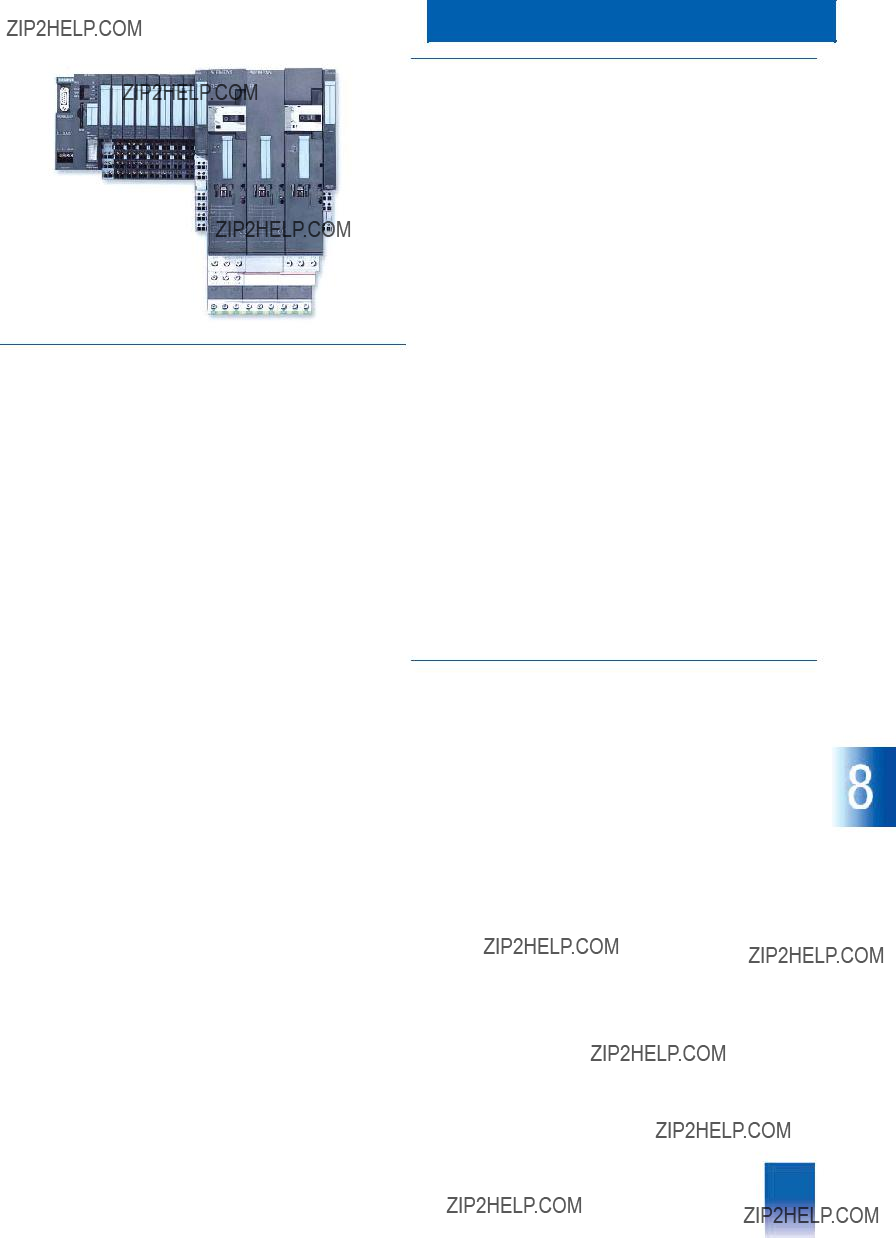
This catalog is out of date, see note on page 3
Process I/Os
ET 200S
ET 200S
???Overview
The ET 200S is a
The ET 200S has a design with independent wiring, i.e. the wir- ing is carried out using terminal modules which function as a supporting system for power modules, electronics modules and consumer feeders. The terminal modules are latched onto a rail according to EN 50 022 and can be prewired and tested without I/O modules. This design also supports hot swapping of
I/O modules.
???Design
The following components are available for the ET 200S distrib- uted I/O system:
???Interface module to connect the ET 200S to the
???IM 151/CPU or IM 151/CPU FO with additional integrated CPU 314 for preprocessing of process data
???Terminal modules for DIN rail mounting including terminals (keyed connection system permits increased vibration resis- tance of 5 g); rail system for power modules, electronics mod- ules and consumer feeders
???Power modules for electronics modules and consumer feed- ers;
for monitoring and fusing the load and sensor power supplies, and for monitoring the auxiliary voltages for a group of consum- er feeders
???Electronics modules: analog and digital I/O modules, as well as special process modules (e.g. for recording SSI sensor val- ues, or for universal counter functions)
???Consumer feeders (modules for switching and protecting any
-Direct starters
-Reversing starters
Configuration limits when used on AS 488
Up to 32 modules can be inserted per I/O system.
The maximum address range of all inserted I/O modules is 122 byte for input data and 122 byte for output data. This limit is irrelevant to the CPU version.
The maximum number of parameters is limited to 244 byte per station. Process modules such as the counter module have long parameter sets, permitting the parameter limit to be reached pri- or to the limiting length of the process data.
???Configuration
Configuration and parameterization
The ET 200S distributed I/O systems are configured and param- eterized using COM PROFIBUS.

This catalog is out of date, see note on page 3
Process I/Os
ET 200S
ET 200S
???Ordering Data

This catalog is out of date, see note on page 3
Process I/Os
ET 200S
ET 200X, ET 200U and ET 200B
ET 200X
The ET 200X distributed I/O system with its modular design and degree of protection IP 65/67 is predestined for use at machine level outside the control cabinet. The ET 200X consists of a ba- sic module for connection to
The extension modules are mounted
Design
Standard modules
???Digital input/output module with 4, 8 or 16 channels
???Relay output module with 4 or 8 channels
???Analog input/output module with 2 or 4 channels
Ex modules
???Digital input/output module
???Analog input/output module
Function modules
???IP 262
The RIP and KRIP drivers for the IP 262
Other modules
For all other I/O modules, you must check in each individual case whether operation with standard drivers is possible (on re- quest).
See Catalog ST 50 from 1998 for further information and techni- cal data on ET 200U (including I/O modules).
???Ordering Data
Order No.
The following extension modules are available:
???Digital inputs/outputs
???Analog inputs/outputs
???Communications processor for linking to
???Pneumatics module with integral valves
???Pneumatics interface to accommodate a CPV valve island from FESTO (max. 1 per unit)
???Load feeders to control any
???SITOP power DC 24 V power supply (option)
See Section "Distributed I/Os" in the mall/CA01 or Catalog IK PI for further information and ordering data.
ET 200U
ET 200U is a modular I/O system with degree of protection IP 20 which is no longer actively marketed. It comprises:
???An IM 318 interface module for connection to
???An internal bus designed using bus modules and with slots for I/O modules
???I/O modules from the SIMATIC
???A power supply module if necessary.
The IM 318 interface module, bus modules and power supply module are mounted on a DIN rail.
The power supply module is only required if a DC 24 V supply is not available for the IM 318 interface module.
The ET 200U is a passive station (slave) on the
IP 262
ET 200B
The ET 200B is a small, compact I/O system with degree of pro- tection IP 20. It consists of a terminal block and an electronics block. The terminal block is the supporting assembly for an elec- tronics block, and is available in various versions. Many different versions of electronics blocks are available with digital or analog input and output channels.
The ET 200B is primarily used where only a few inputs/outputs are required or where only a small mounting depth is available.
The interface for
The following electronics blocks are provided for use of the ET 200B as a distributed I/O system for AS 488/TM automation systems:
???Digital input, 16/32 channels, DC 24 V,
???Digital output, 16/32 channels, DC 24 V,
???Relay module, 8 outputs, DC 24 V/60 V, floating
???Analog input, 4/8 channels, floating, for Pt 100/thermocouple,
?? 1.25 V, ?? 2.5 V, ?? 5 V, ??10 V, 0(4) to 20 mA
???Analog output, 4 channels, ?? 10 V, +10 V, ?? 20 mA, 0(4) to 20 mA
I/O modules from the SIMATIC
See Section "Distributed I/Os" in the mall/CA01 for further infor- mation, technical data and ordering data on the ET 200B.
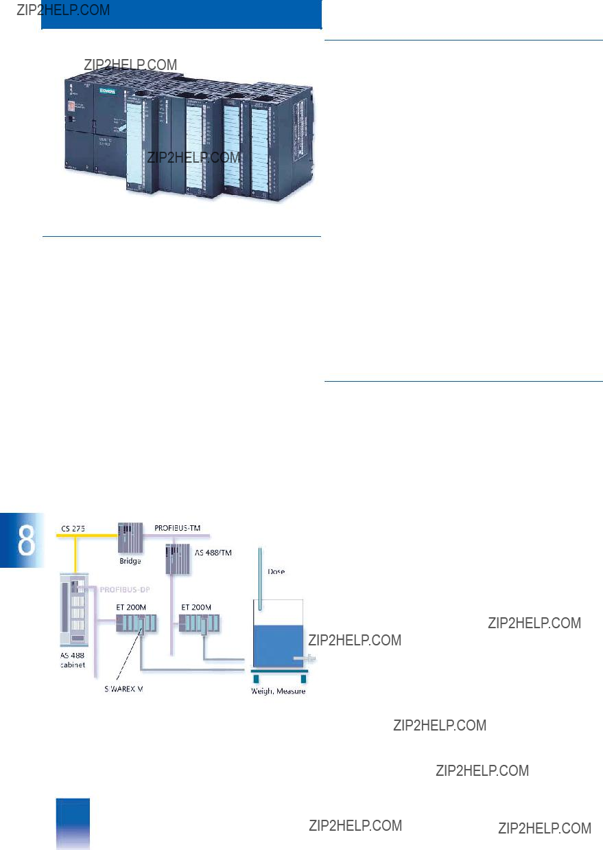
This catalog is out of date, see note on page 3
Process I/Os
SIWAREX M
SIWAREX M
???Overview
In a process engineering application, SIWAREX M handles exe- cution of all weighing functions as well as the
SIWAREX M can be used to design net weight scales, single- component or
The downloadable SIWA driver block integrates the SIWAREX M weighing and dosing electronics with verification capability into the TELEPERM M process control system.
The SIWAREX M function modules are operated in ET 200M dis- tributed I/O systems. It is irrelevant whether the ET 200M is con- nected to the automation system via line 1 or 2 of the PROFIBUS- DP. Up to seven SIWAREX M function modules can be plugged into an ET 200M of standard design with bus connectors. Up to four SIWAREX M function modules can be plugged into an
ET 200M with active bus modules (for the hot swapping func- tion).
???Configuration
SIWA driver block
The AS 388/TM and AS 488/TM automation systems additionally require the SIWA driver block for connection of SIWAREX M. SIWA is a standard AS function block with the system type num- ber 138, and can be downloaded into the automation system via a commissioning terminal.
Users can call the following functions using
???"Measure"
???"Tare"
???"Start"
???"Pause" (stopping of a dosing procedure)
???"Continue" (continuation of a dosing procedure)
Status scanning is additionally possible for diagnostics.
The listed jobs can be activated using
Note:
The SIWA driver block can only execute on the automation sys- tem whose serial number is stored in the SIWA software. If the SIWA driver block is subsequently ordered, it is therefore neces- sary to specify the memory card serial number of the automation system on which the SIWA is to be installed.
???Ordering Data
Connection of SIWAREX M modules, configuration example
ET 200M with SIWAREX M function modules can be operated on lines 1 and 2 of the

This catalog is out of date, see note on page 3
Process I/Os
???Overview
The transmission technology of the
Connecting
Properties and application features of the
???Networking of transmitters, valves, actuators etc. via a serial bus system
???
???Integration possible into existing fieldbus applications based on
???Power supply to field devices via data cable
???"Intrinsic safety" (type of protection EEx[i]) permits applications in hazardous area
???Transfer of automation functions (intelligence) into the field de- vices
???Remote parameterization, e.g. using Process Device Manager (PDM)
???Preventive maintenance and diagnostics
???Reduction in hardware and engineering costs by saving of I/O modules, cabling and connections
???Satisfies the requirements of the chemical and processing in- dustries.
Delivery forms
Connection of the
???Full license for connection of the
???Partial license for connection of the
Configuration example of the
TELEPERM M

This catalog is out of date, see note on page 3
Process I/Os
Connecting
???Design
Connection of
The
DP/PA couplers are available in two versions: an Ex version with max. 100 mA output current and a
Four screw terminals are available for the
Each PA field device occupies a PROFIBUS address on the DP line.
Connection of
The
???Mode of operation
Users have access to the field devices on the
Limitation:
When linking PA field devices via the DP/PA link, the DP device must accept parameterization telegrams with a length of
10 byte.
The DP/PA link comprises the IM 157 interface module and up to 5 DP/PA couplers which are connected together via
Four screw terminals are available on the DP/AP couplers of the
Ex version, the DP/PA coupler is always at the end of the cable, and the terminating resistor is activated. Only two screw termi- nals are available for the
Only the DP/PA links occupy a PROFIBUS address on the
DP line. Each DP/PA link provides a separate address range for each of the subordinate PA field devices.
The communications interface permits operation of the

This catalog is out of date, see note on page 3
Process I/Os

This catalog is out of date, see note on page 3
Bus communication
Siemens PLT 112 ?? 2002
This catalog is out of date, see note on page 3
Bus communication
???Overview
The AS 488/TM and AS 388/TM automation systems are connected to one another, to OS 525 or
The connection to
???Using an EXM 478 extension module with IF 964 interface module for AS 488/TM systems and
???Using an EXM
???Mode of operation
The PROFIBUS access procedure is similar to that of the CS 275 bus system, and operates according to the "Token passing" pro- cedure corresponding to EN 50 170 (PROFIBUS). Characteristic for
A data transmission rate of 1.5 Mbit/s is used for communication between the TELEPERM M components via the
Despite the much higher data transmission rate compared to the CS 275, only the same performance data are guaranteed for the
However, if the
Transmission systems
PROFIBUS offers a comprehensive range of network compo- nents for electrical and optical transmission systems.
???Electrical network
Shielded, twisted
The individuals segments are connected using repeaters.
???Optical network
The optical version of the PROFIBUS is suitable for long dis- tances, and is insensitive to electromagnetic interferences. Glass
The OLM can be used to design an optical network with a mul- tipoint, ring or star structure.
???Mixed network
Mixed structures are possible comprising electrical and optical PROFIBUS networks. OLMs are used for the transition between the two media.
There is no difference between the electrical
Possible bus configuration: linear and tree structures of the PROFIBUS electrical network

This catalog is out of date, see note on page 3
Possible bus configurations:
You can find further information and conditions on the PROFIBUS in the Catalog IK PI "Industrial communications and field devices".
???Configuration
The electrical PROFIBUS network can be configured with a mul- tipoint or tree structure. The most important features of the elec- trical network are:
???
???RS 485 transmission procedure (according to EIA)
???Bus connector (alternative: bus terminals) for connection of PROFIBUS stations
???Simple, uniform mounting and earthing concept
???Simple installation
The electrical network can also be operated together with an op- tical PROFIBUS network. The optical network can be configured with optical link modules OLM in a multipoint, ring or star struc- ture. The most important features of the optical network are:
Bus communication
Bus connector
The bus connector can be used to directly connect the stations on the PROFIBUS together in
With the AS 388/TM automation system, the bus connector is plugged onto the IF 964 interface module on the EXM
An optical link module OLM can also be connected to the bus connector.
The bus connectors are available with a pivoted or axial cable outlet, in each case with degree of protection IP 20.
The standard connection for
Electrical bus terminal
The RS 485 bus terminal is used if a variable design is desired for the bus connections. The bus terminal is snapped onto a DIN rail for assembly. As the result of a selectable, integral ter- minating resistor, no additional installation is required.
Note:
The total length of the bus terminal spur lines per segment (max. 200 m PROFIBUS cable) can be up to 10 m; i.e. max. 6 bus ter- minals are permissible for the recommended bus terminals with 1.5 m spur line; additional stations must be connected using bus connectors. The PROFIBUS design guidelines must be ob- served (see SIMATIC NET manual "PROFIBUS networks" (6GK1
Optical link module
PROFIBUS networks can be configured with the optical link modules OLM in a multipoint, ring or star structure. They permit high availability by means of a redundant power supply and re- dundant cables.
???High availability for redundant optical ring with OLM
???Wide range
???Cascading of OLMs possible
???Insensitive to electromagnetic interferences
???Electrical isolation
The solution with optical link modules is more appropriate than the electrical network for signal transmission over longer dis- tances, and is insensitive to overvoltages, e.g. resulting from lightning. The equipotential bonding which is required when us- ing an electric
???Either glass or plastic
???High degree of adaptation to local conditions
Recommendation:
Independent of the technical possibilities, we recommend that you use one optical link module OLM per station (AS/OS/ES) for availability reasons.
Up to 41 OLMs can be connected in series permitting a distance of 21 km to be covered at the used data transmission rate of 1.5 Mbit/s and the resulting max. cable length of 530 m.
When using a
There are several designs of OLM (see Catalog IK PI); the type OLM/G12 for glass
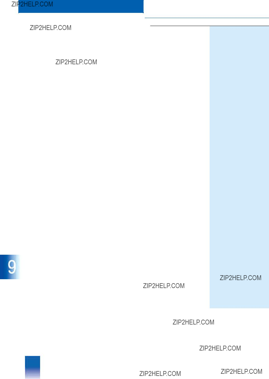
This catalog is out of date, see note on page 3
Bus communication
Optical bus terminal (OBT) for PROFIBUS
The OBT (optical bus terminal) is used to connect a PROFIBUS station without an integral optical interface to an optical line with PROFIBUS stations with integral interface and OBT.
The PROFIBUS station is connected to an RS 485 interface of the OBT via a cable terminated at both ends, e.g. connecting cable
Please refer to Catalog IK PI "Industrial communications and field devices" and the SIMATIC NET manual "PROFIBUS net- works" (6GK1
???Ordering Data
Transmission media
The ordering data include the transmission media for all types of PROFIBUS connection referred to above and recommended for use with the AS 388/TM and AS 488/TM automation systems.
Please refer to Catalog IK PI "Industrial communications and field devices" for further components and for information on pos- sible bus configurations.
The following table lists the max. permissible cable lengths which can be achieved with the used data transmission rate of 1.5 Mbit/s:
System connection for AS 488/TM
EXM 478 module with IF 964 interface module
An AS 488/TM automation system can only be connected to ei- ther the
The AS 488/TM automation system is connected to PROFIBUS- TM via an IF 964 interface module in an EXM 478 extension module. The standard connection is the interface module in the second extension module. One of the three slots in the first EXM 478 module can be used if they are not all occupied al- ready. However, this requires adaptation of the interface assign- ment in the initialization files when configuring.
Bus connectors or bus terminals can be plugged directly onto the IF 964 interface module.
RS 485 bus terminal for
PROFIBUS
with
???Without programming device in- terface
???With
Optical link module for
PROFIBUS, OLM/G12
Optical link module for glass
Optical bus terminal for
PROFIBUS, OBT
Optical bus terminal for connec- tion of a PROFIBUS station, with- out integral optical interface to the optical PROFIBUS, without Sim- plex connector
1.5 m long
3 m long
Bus cables for PROFIBUS
???Standard cable
???Bus cable with PE sheath, for food and drink industry
Standard cable, can be fanned out, cut to length
(specify length in .... m)
Max. available length 4000 m
BFOC connector
for standard
EXM 478 extension module
to accommodate 3 interface mod- ules
IF
6GK1
6GK1
6GK1
6GK1
6XV1
6XV1
6XV1
See Catalog IK PI for precut/pre- assembled cables
6GK1
6ES7
6ES7
This catalog is out of date, see note on page 3
Bus communication
CS 275
CS 275
???Overview
In the following, you will be provided with information relevant to connection of the AS 488/TM to the CS 275 bus system. Please refer to Catalog PLT 130 for detailed information on the TELEP- ERM M CS 275 bus system, in particular on design and mode of operation.
???Configuration
TPM 478 interface module
The AS 488/TM automation system and the
???CS 275 functionality
A powerful CPU processes the communications functions to the CS 275 bus system. The functionality of the TPM 478 inter- face module corresponds to that of the
An AS 488/TM automation system can only be connected to ei- ther the
???TELEPERM I/O functionality
In the AS 488/TM automation system, the TPM 478 module to- gether with the TBX 478 module also provides the interface to the TELEPERM M I/Os. The two modules provide two I/O bus interfaces for TELEPERM M basic and extension cabinets, and provide the +5 V bus for the I/O bus logic.
Only one TPM 478 module is required for both functionalities, i.e. for the CS 275 functionality and the TELEPERM M
I/O functionality.
Configuring
Configuring depends on whether the TPM 478 module is used in the AS 488/TM automation system or in the
The commissioning terminal is used as the configuring tool. The commissioning terminal software is included in the scope of de- livery of the system software for the AS 488/TM system and the
The configuring data are transmitted from the commissioning terminal to the memory card of the AS 488/TM system using a transfer file. The current system parameters are loaded into the system memory of the CPU when the system is restarted, and the AS 488/TM system executes automatically on the CS 275 system bus.
When configuring the
???Ordering Data

This catalog is out of date, see note on page 3
Bus communication
CS 275
CS 275
Remote bus cable with addi- tional armoring 1)
???To increase the tensile strength to 25000 N
???To protect against mechanical damage and rodents
Specify length in each case in plain text (max. 4 km)
Length ..... m
Length ..... m
1) Ordering address:
LEONI SPECIAL CABLES FRIESOYTHE GmbH & Co KG
Pehmertanger Weg
Tel: +49 (4491) 292 171 or
Tel: +49 (4491) 292 122

This catalog is out of date, see note on page 3
???Overview
The
The
The
Bus communication
The hardware of the
Limits:
The
The
S7 automation systems.
Design of

This catalog is out of date, see note on page 3
Bus communication
???Configuration
Station addresses
The address range defines the stations which are accessible on the
Example:
If max. 20 stations with addresses 40 to 59 are to be connected on the PROFIBUS, the
???CS 275 bridge station address (TA) = 39
???Address range: 21
With the max. possible number of 31 stations on the PROFIBUS- TM, 32 vacant station addresses must therefore be present in ascending order on the CS 275 bus. Double assignment of sta- tion addresses on the CS 275 bus and on the
Performance data:
The bridge provides the following data throughput [tele- grams/s]: either 30 long telegrams or 60 short telegrams in both directions together. There is a reserve for acyclic message transmission of 75 messages/s over a period of 10 s, where
5 messages are assumed per MKS/status telegram.
???Technical Specifications
Basic device
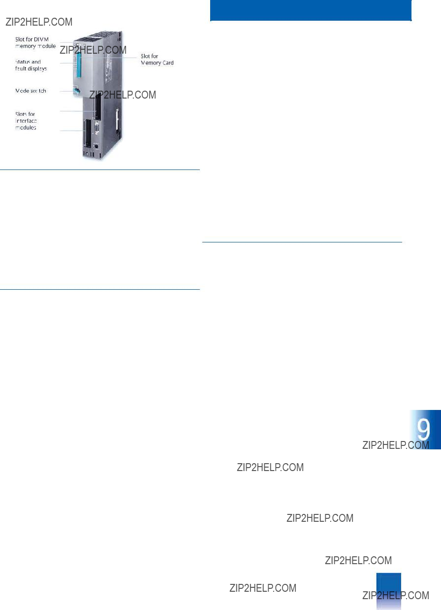
This catalog is out of date, see note on page 3
Bus communication
Central processing unit
The inputs and outputs are electrically isolated. The module electronics (ASIC) is protected against overvoltages by appro- priate circuitry measures.
The digital inputs comprise 8 channels organized in groups of 4 x 2 channels. The current consumption is 8.5 mA with an input level of DC 24 V.
An input delay of 500 ms or 3 ms can be parameterized for all input channels together.
The cable length is:
??? unshielded 200 m (for 500 ms) or 600 m (for 3 ms)
??? shielded 1000 m.
The digital outputs also comprise 2 x 4 channels. With DC 24 V, the max. output current is 100 mA. The outputs are protected against
A
???Overview
CPU
The CPU
The front panel of the rugged, compact plastic housing contains:
IF
The IF
???LEDs for status and fault display
???Operating mode switch
???Slot for a memory card from which the coupling software and bus parameters are loaded into the main memory when start- ing up
???2 slots for interface modules
???Design
Memory module (set with 2 x 8 Mbyte)
The CPU
I & C monitoring
I & C monitoring functions can be implemented using the IF
The interface module is inserted in the EXM
The IF
???door contact
???excess temperature
???monitoring of optical link module OLM
and to activate a cabinet lamp or horn.
Cable monitoring, e.g. to detect an
???Ordering Data
This catalog is out of date, see note on page 3
Bus communication
Power supply modules
???Overview
PS 405 and PS 407 load power supplies
The modules of the
Depending on the input voltage, either the PS 407 (for
AC 120/230 V) or PS 405 (for DC 24 V) power supply module is required.
The power supply module is inserted in the subrack on the left. It is designed in a casing, and is cooled by natural convection. The front panel of the module contains:
???LEDs for display of correct output voltages, correct backup battery voltage, and internal fault
???Key for fault acknowledgment
???On/off switch for output voltages
???Battery compartment (hidden) for backup battery (not relevant to
???Switch (hidden) for activation of battery monitoring
???Power supply selector (hidden) for AC 120/230 V
???Power supply connection (hidden) with
???Ordering Data
This catalog is out of date, see note on page 3
Connection to
???Overview
The
???Ordering Data
Bus communication
Connection to
Connection to CS 275
Connection to CS 275
???Overview
The
???Ordering Data
for connection to CS 275 and for TELEPERM M I/Os
See Catalog IK PI for further PROFIBUS components.

This catalog is out of date, see note on page 3
Bus communication
Packaging system
???Overview
UR2 rack
The UR2 rack is the basic mechanical frame of the AS 488/TM automation system. It accommodates the system modules (CPU, load power supply, EXM 478, TPM 478 and TBX 478), provides the operating voltages for the modules, and connects the individual modules via the backplane bus.
The rack comprises:
???Aluminium rail with threaded bolts for securing the modules, and lateral recesses for mounting the rack
???Plastic components as guides when swinging in the modules
???Connection for PE conductor
???Backplane bus with plug connections
Migration rack
The migration rack for
???Ordering Data
???Overview
The system software of the
The runtime software is supplied on a memory card, and con- tains the system coupling software, the initialization data, and the configuring parameters for the bus configuration.
The commissioning terminal software for PCs/programming de- vices is supplied on a
???Ordering Data
comprising:
???Runtime software
???Commissioning terminal soft- ware for PC/programming de- vice, on
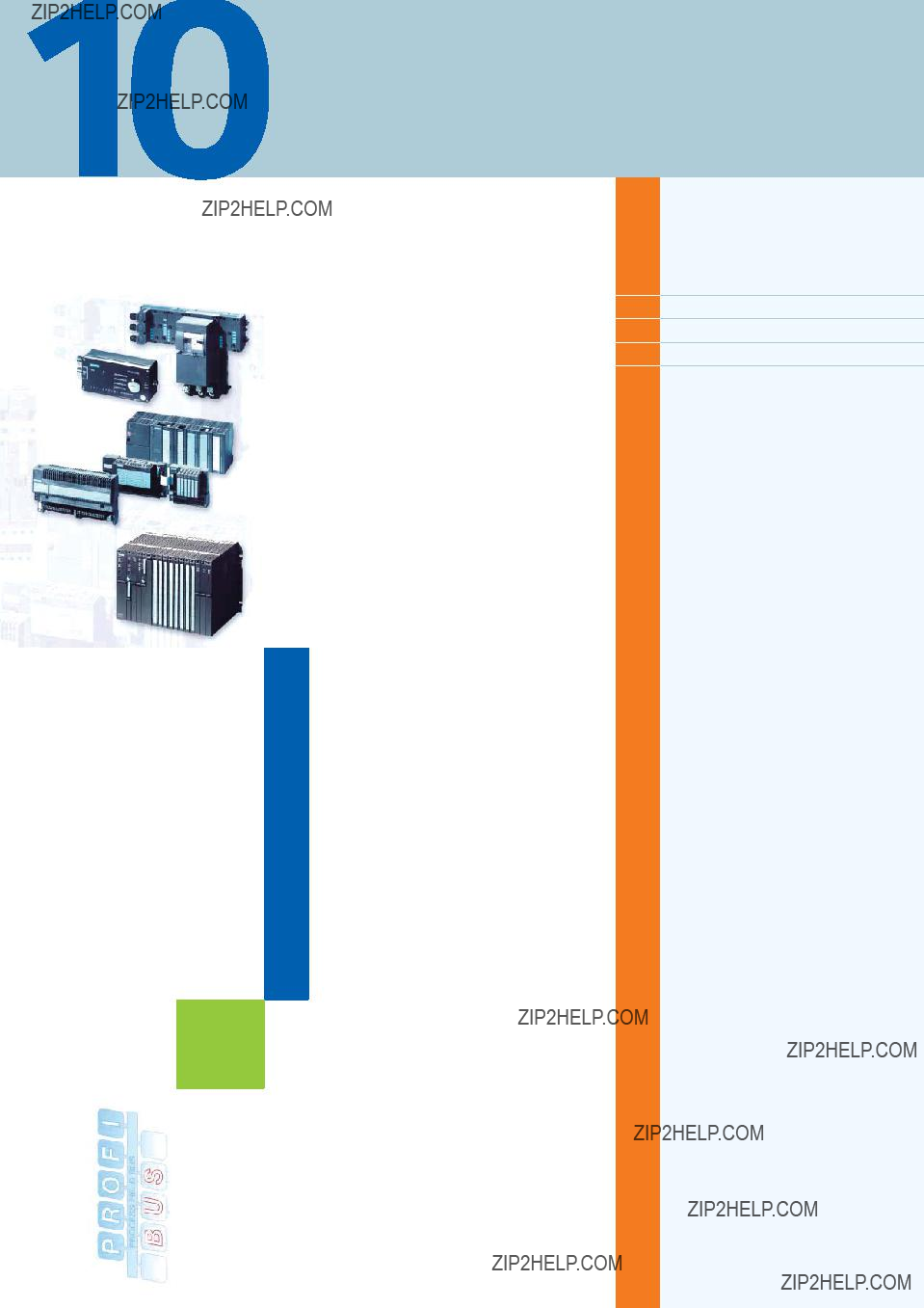
This catalog is out of date, see note on page 3
Data couplings with other systems
10/2 Introduction
10/3
10/5 Serial coupling
Siemens PLT 112 ?? 2002

This catalog is out of date, see note on page 3
Data couplings with other systems
Introduction
Data couplings
???Overview
A basic differentiation is made for data coupling of the AS 488/TM with other systems between:
???System couplings via PROFIBUS as the data bus and
???direct couplings via special interface modules.
The overview table shows the current interfaces for system and direct couplings together with the most important features of the interface modules.
Interface modules are operated in a slot for I/O modules or in an extension unit of the CPU (EXM 478).
With the serial coupling, the interface modules automatically handle data transfer with the coupling partner. Data transfer for the serial coupling is via the transfer RAM of the interface modu- le and the process image of the AS 488/TM. With the alternative data bus coupling with PROFIBUS, the data are transferred bet- ween the drivers and the respective coupling partners via the special AG/AG coupling software in the AS operating system and the interface module.
When selecting the type of coupling suitable for the respective application, the following factors can also be important in addi- tion to the type of coupling partner:
???Distance from coupling partner
???System topology, number of partner systems, and type of part- ner system
???Earthing concept and lightning protection measures
???Migration strategy: retention of existing configuration, or recon- figuration
???Performance
If the coupling is between different buildings or over large dis- tances within buildings, it is recommendable for potential diffe- rence reasons to use optical transmission techniques (fiber- optic cables) for the PROFIBUS connection or to alternatively use a serial coupling.
The serial coupling supports any protective measures against static and dynamic potential differences (earthing, lightning pro- tection) because of the low number of conductors and electrical isolation. The data transmission rate can be varied within certain limits for this type of coupling. On the one hand, this influences the transmission rate and thus the cycle time, in addition the se- lected data transfer rate has an influence on the maximum dis- tance which can be covered.
The drivers of block type S5KE/S5KS required for system and di- rect couplings are components of the standard system software in the case of the serial coupling. For the AG/AG coupling via PROFIBUS as the data bus, extended S5KE/S5KS drivers are provided as components of the optional AG/AG coupling softwa- re for downloading.
Coupling with systems from other vendors
The serial coupling with interface module 6DS1

This catalog is out of date, see note on page 3
Data couplings with other systems
System couplings
???Overview
AG/AG coupling with SIMATIC S5/S7 central controllers
The devices of the SIMATIC
AS 388/TM and AS 488/TM automation systems via an additio- nal
To reduce the load on the CS 275 or
Via an AS 488/TM automation system with AG/AG coupling, sys-
???SIMATIC S7 stations: FC blocks AG_SEND and AG_RECV; these blocks are part of the NCM S7 package
???SIMATIC PCS 7 stations: blocks FR_AGSEN and FR_AGRCV
???SIMATIC S5 stations: handling blocks SEND and RECEIVE
???TELEPERM AS x88: standard function blocks S5KS [AGAG] and S5KE [AGAG]
???With OPC stations and those from other vendors, the blocks/procedures are referred to in the associated documen- tation.
Access to the FDL interface is usually only possible for the cou- pling partners via a specifically installed communications pro- cessor:
An IF 964 interface module in the EXM 478 extension module as well as the additionally loaded
With the AS 488/TM automation system, the IF 964 interface mo- dule should preferably be connected to the bottom of the three EXM 478 slots. If all EXM slots are already occupied, e.g. by re- trofitted modules, a second EXM 478 extension module is addi- tionally required.
EXM 478 extension module
If all slots in the first EXM 478 extension module are already oc- cupied, a second EXM 478 extension module is required for connection of the IF 964 interface module. This second EXM 478 module has three locations for interface modules.
???Mode of operation
The
Using the FDL services SDA (send data to one station, with ack- nowledgment of receipt) and SDN (send data to one or all stati- ons, without acknowledgment of receipt; broadcast) of the European standard EN 50 170, data blocks with a maximum length of 240 byte are transmitted in the send and receive direc- tions, where the receive telegrams occupy the first 4 byte with the internal AS 488 address (i.e. max. 236 byte useful data).An initialization file can be used to set the transmission rate between 9.6 kbit/s and 1.5 Mbit/s.
Note:
A coupling partner is addressed using its PROFIBUS station address and one of the connection endpoints (SAP) configured for communication with the AS 488. With SIMATIC, the connec- tions are either configured completely (SIMATIC S7: specified connections; SIMATIC S5: AG/AG connections) or only partially (SIMATIC S7:
This catalog is out of date, see note on page 3
Data couplings with other systems
System couplings
???Technical Specifications???Ordering Data
Telegram length
Important note:
When subsequently ordering the AG/AG coupling software, it is essential to specify the serial number of the memory card for the automation system on which this functional extension is to be in- stalled. The
The current version of the AG/AG coupling software can be used starting with version M02.00 or M01.06 of the AS x88/TM system software. In order to use the full functionality of PROFIBUS- AG/AG, it is necessary to have the version M02.01 or M01.07 of AS x88/TM.
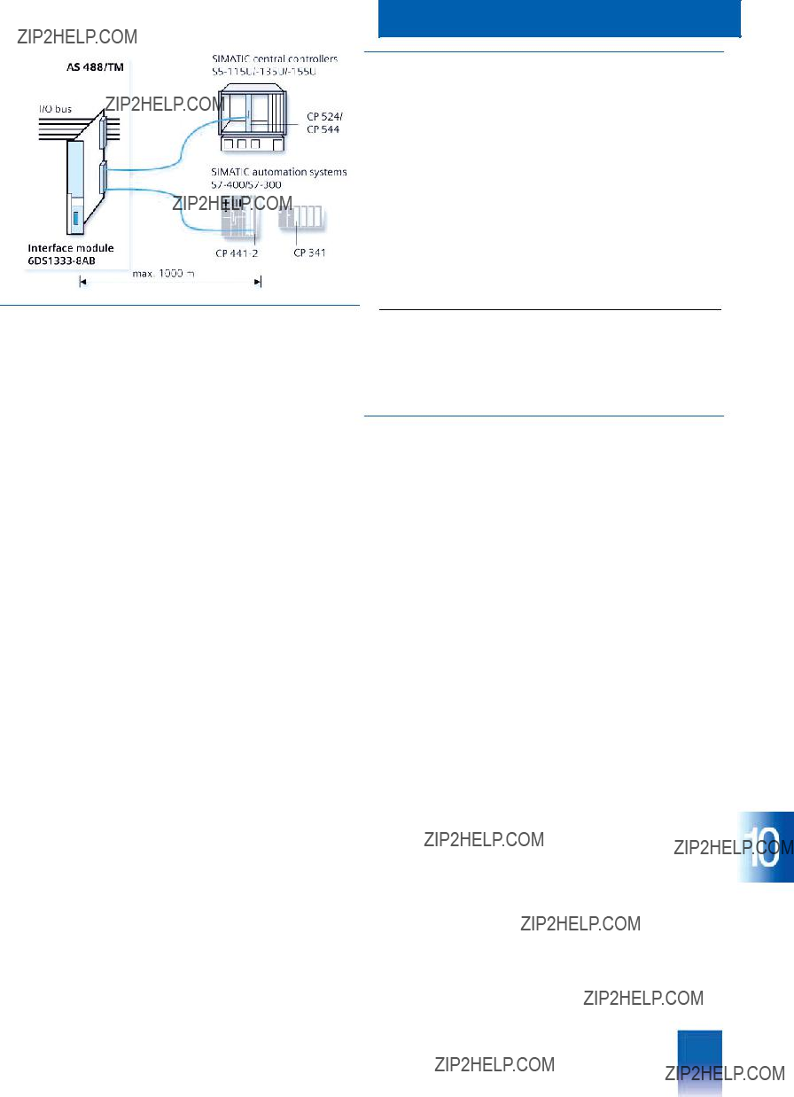
This catalog is out of date, see note on page 3
Data couplings with other systems
Direct couplings
Serial coupling
???Overview
In certain cases it may be meaningful to accommodate comple- te sections of an automation program in a subordinate automa- tion level. This reduces the load on the automation system, saving valuable computing time. This is particularly important for automation tasks with short cycle times which place a high load on the computing capacity of a CPU. Furthermore, subordinate programs can also be generated and tested independent of other parts of the program.
The following are required to couple the AS 488/TM automation system with SIMATIC S5
???Interface module for SIMATIC S5/S7 central controllers
???Connecting cable
???For SIMATIC S5:
CP 524 or CP 544 communications processor
See Catalog ST 50 for interface modules, parameterization tools and accessories
???For SIMATIC
CP 341 communications processor with
???For SIMATIC
CP
See Catalog ST 70 for interface modules, parameterization tools and accessories
???Design
The interface module for SIMATIC S5/S7 central controllers, 6DS1
2 backplane connectors for the I/O bus interface, and two serial interfaces for connecting a SIMATIC S5/S7 central controller.
The interface module for SIMATIC S5/S7 central controllers can be inserted into any slot for I/O modules of an AS 488/TM auto- mation system or an ES 100 K extension system. SIMATIC S5/S7 central controllers can be connected to each of the two chan- nels.
A shielded,
???Mode of operation
The data arriving in parallel via the I/O bus of the automation sys- tem are saved cyclically in the transfer RAM of the interface mo- dule for SIMATIC S5/S7 central controllers. SIMATIC S7 central controllers operate with SEND/RECEIVE and S5 analog value format. The SIMATIC S5 central controllers can read the transfer RAM using fetch telegrams. The send component of the inter- face module reads the data from the transfer RAM, supplements them into a complete telegram, and passes this on to the SIMATIC S5/S7 central controller via the serial interface.
The telegrams sent by the SIMATIC S5/S7 central controller are checked for reliability in the receive component of the interface module, and the contained data are saved in the transfer RAM. The automation system reads this data cyclically out of the trans- fer RAM.
The data transfer between the AS 488/TM CPU and the interface module for SIMATIC S5/S7 central controllers is handled via the S5KS and S5KE driver blocks in the automation system. Either the 3964 or 3964 R transmission procedure (selectable) is used for the data transmission between interface module and SI- MATIC S5/S7 central controller.
RK 512 is used as the protocol. In the process, the SIMATIC S5 central controller sends or fetches the data using telegrams. The TELEPERM M interface module is the passive communication station. SIMATIC S7 central controllers operate with SEND/RE- CEIVE and S5 analog value format.

This catalog is out of date, see note on page 3
Data couplings with other systems
Direct couplings
Serial coupling
???Technical Specifications
Power supply
???Ordering Data
This catalog is out of date, see note on page 3
Appendix
Siemens PLT 112 ?? 2002
This catalog is out of date, see note on page 3
Appendix
Software licenses
Software
???Software types
Software requiring a license is categorized into types. The following software types have been defined:
???Engineering software
???Runtime software
Engineering software
This includes all software products for creating (engineering) user software, e.g. for configuring, programming, parameterizing, test- ing, commissioning or servicing.
Data generated with engineering software and executable pro- grams can be duplicated for your own use or for use by
Runtime software
This includes all software products required for plant/machine op- eration, e.g. operating system, basic system, system expansions, drivers, etc.
The duplication of the runtime software and executable programs created with the runtime software for your own use or for use by
You can find information about license fees according to use in the ordering data (e.g. in the catalog). Examples of categories of use include per CPU, per installation, per channel, per instance, per axis, per control loop, per variable, etc.
Information about extended rights of use for parameteriza- tion/configuration tools supplied as integral components of the scope of delivery can be found in the readme file supplied with the relevant product(s).
???License types
Siemens Automation & Drives offers various types of software license:
???Floating license
???Single license
???Rental license
???Trial license
???Downgrading
The licensee is permitted to use the software or an earlier ver- sion/release of the software, provided that the licensee owns such a version/release and its use is technically feasible.
???Delivered versions
Software is constantly being updated. The following delivery versions
???PowerPack
???Upgrade
can be used to access updates.
Existing bug fixes are supplied with the ServicePack version.
PowerPack
PowerPacks can be used to upgrade to more powerful software. The licensee receives a new license agreement and CoL (Certifi- cate of License) with the PowerPack. This CoL, together with the CoL for the original product, proves that the new software is li- censed.
A separate PowerPack must be purchased for each original li- cense of the software to be replaced.
Upgrade
An upgrade permits the use of a new version of the software on the condition that a license for a previous version of the product is already held.
The licensee receives a new license agreement and CoL with the upgrade. This CoL, together with the CoL for the previous product, proves that the new version is licensed.
A separate upgrade must be purchased for each original license of the software to be upgraded.
ServicePack
ServicePacks are used to debug existing products. ServicePacks may be duplicated for use as prescribed according to the number of existing original licenses.
Floating license
The software may be installed for internal use on any number of devices by the licensee. Only the concurrent user is licensed. The concurrent user is the person using the program. Use begins when the software is started.
A license is required for each concurrent user.
Single license
Unlike the floating license, a single license permits only one instal- lation of the software.
The type of use licensed is specified in the ordering data and in the Certificate of License (CoL). Types of use include for example per device, per axis, per channel, etc.
One single license is required for each type of use defined.
Rental license
A rental license supports the "sporadic use" of engineering soft- ware. Once the license key has been installed, the software can be used for a specific number of hours (the operating hours do not have to be consecutive).
One license is required for each installation of the software.
Trial license
A trial license supports
Detailed explanations concerning license conditions can be found in the ???Terms and Conditions of Siemens AG??? (see last page) or with the A&D Mall
http://www.siemens.com/automation/mall
???License key
Siemens Automation & Drives supplies software products with and without license keys.
The license key serves as an electronic license stamp and is also the "switch" for activating the software (floating license, rental li- cense, etc.).
The complete installation of software products requiring license keys includes the program to be licensed (the software) and the license key (which represents the license).
???Certificate of License
The Certificate of License (CoL) is the licensee's proof that the use of the software has been licensed by Siemens.
A CoL is required for every type of use and must be kept in a safe place.
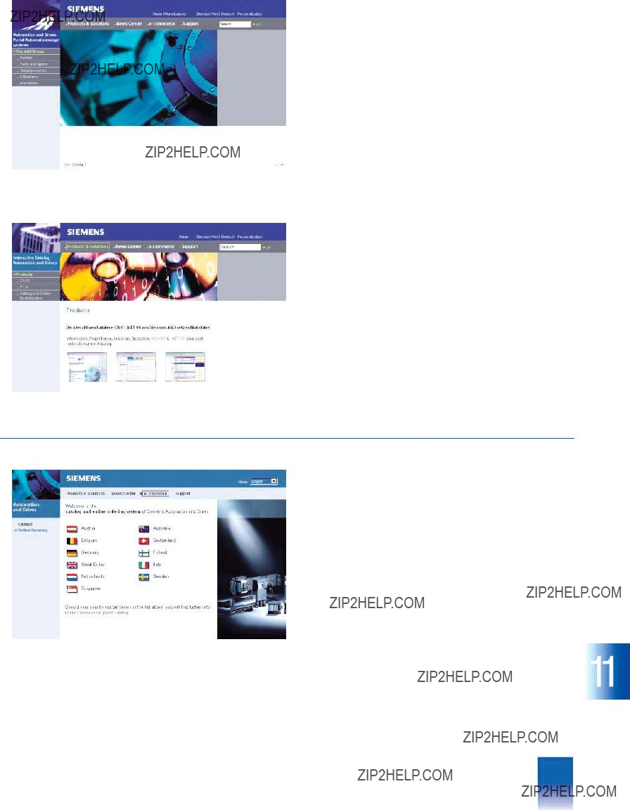
This catalog is out of date, see note on page 3
For example, powerful search functions make it easy to find the required products, which can be immediately checked for availability. Customer- specific discounts and preparation of quotes can be carried out online as well as order tracking and tracing.
Please visit the Siemens Mall on the Internet under:
www.siemens.com/
automation/mall
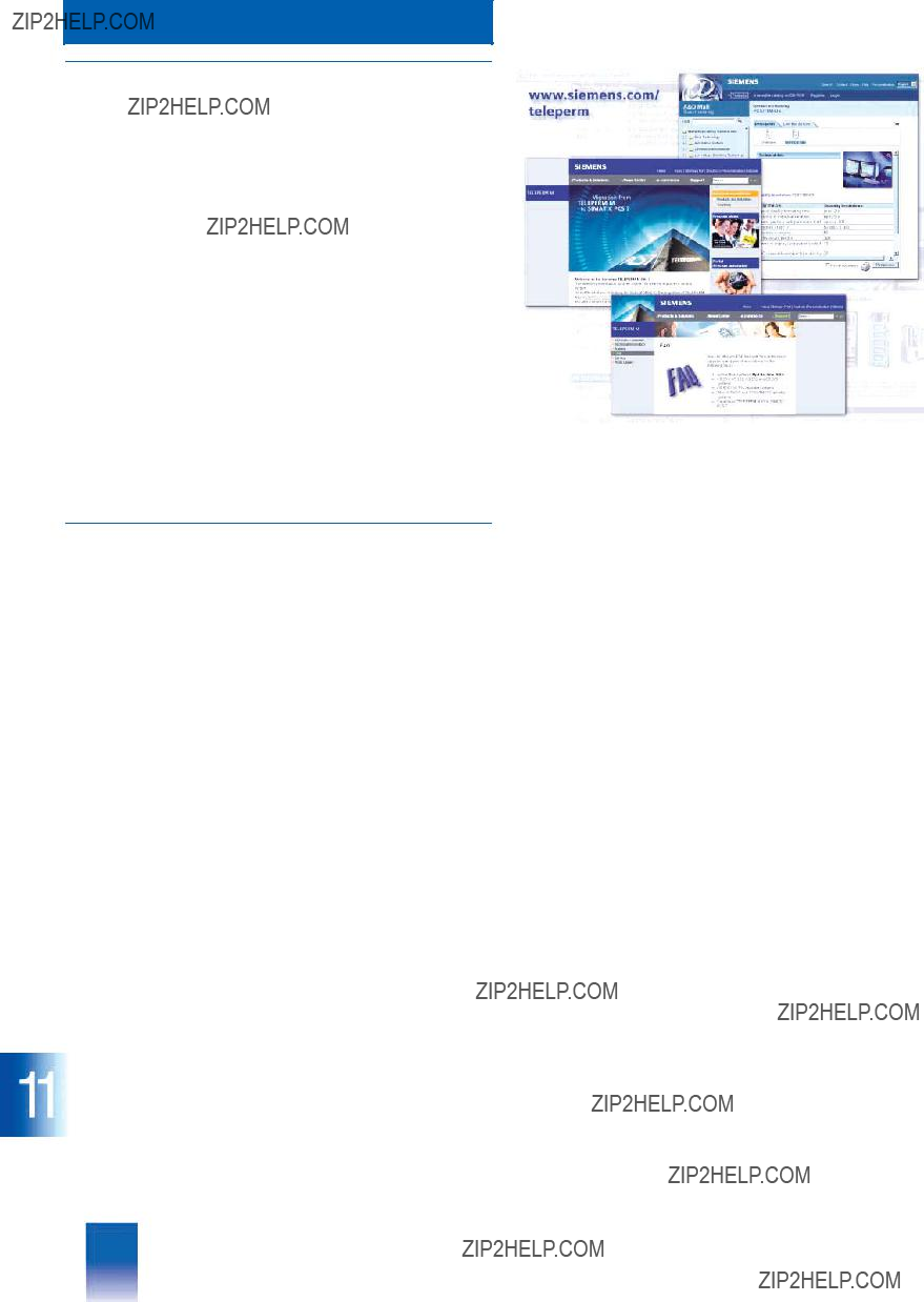
This catalog is out of date, see note on page 3
Appendix
Internet, Training
???Internet
Informations about the TELEPERM M process control system and the migration to SIMATIC PCS 7 are now presented in our new Internet site
www.siemens.com/teleperm
On the TELEPERM M Site you will find
7Product informations for the complete TELEPERM M system
7Catalog and Online Ordering System (Mall)
7FAQs (Frequently Asked Questions) for automation systems and operator stations
7Catalogs
7Informations on TELEPERM M training
7Data sheets for TELEPERM M I/O modules
7Newsletter for Process Automation
7Portal Process Automation with informations about
SIMATIC PCS 7, Automation in the Chemicals, Pharmaceuti- cals, Glass as well as Process Instrumentation and Analytics.
???Training
Courses in the Training Center Karlsruhe
Effective utilization of a process control system depends on the knowledge and skills of the people who use and operate it. Com- prehensive training of these employees has become one of the most important production factors in the case of
Training for TELEPERM M therefore means:
7Fast,
7Comprehensive knowledge and utilization of the complete system
7Exchange and ideas for solving individual application pro- blems
You can obtain further information on course contents, dates, prices etc. at the following address on the Internet:
www.sitrain.com
Should you have special questions, please directly contact the A&D Training Center in Karlsruhe:
Tel.: +49 721
Fax: +49 721
Alternatively, contact your local Siemens office or representative to obtain information on local training.

This catalog is out of date, see note on page 3
Appendix
Order No. index
???Order No. index
6ES7
6ES7
..................................... 8/5, 9/4, 9/11, 10/4