s

The cordless V.24/RS232 interface for PCs, modems and other equipment

Operating instruction

Please read the safety precautions outlined in these operating instructions before putting the unit into service.

Gigaset M101 Data

ACHTUNG! Schnittkante ggf. auf Titelseite U1 nach au??en versetzen wg. Falz-Ausklappseite

The most important menus

Starting the program

Registering a Gigaset M101 Data

Setting the operating mode

2

Overview

Legend

Front

1. Operating LED,

illuminated when power supply is active,

see "LEDs and buttons" on page 19

2. Data LED, illuminated during data transfer operations

3. Reset key

1 2 3

Back

4. Port for the V.24/RS232 cable

1 = male

2 = female

5. Mains power supply socket for plug-type AC adapter

4

5

3

4

Updates and news on the Internet

Visit our site at:

www.siemens.com/pc-communication-support

(always under construction)

5

Approval and conformity

Your Siemens Gigaset M101 Data has been certified by the Ger- man Federal Office of Telecommunication Approval (BZT). This equipment has been approved in accordance with the EU direc- tive 91/263/EC Telecommunication Terminals.

This data terminal complies with the requirements of the EU di- rectives:

and thus carries the CE mark.

Notes on PC and modem operation

When using a modem, software malfunctions in the PC (e.g. an operating system crash or program errors in the application software) can prevent the cleardown of a modem connection from a telephone line. You incur connection costs for trunk lines that you seize!

Since your Gigaset M101 Data only replaces a serial ca- ble, malfunctions of this kind can also occur here. If such a problem occurs, check the status of your modem and, if applicable, reset it.

In the case of one-sided interruption of the mains supply or complete interruption of your Gigaset M101 Data???s hop, the interface???s status lines are reset to the initial status in the partner station within 2 minutes (a modem then clears down the connection).

Whenever possible, operate the station registered as user at your PC (lokale Station), since any malfunctions on the user side can be displayed, for technical reasons, more quickly than at the base, see "LEDs and buttons" on page 19.

Should the graphic or sound card be affected by interfer- ence from Gigaset M101 Data, rotate Gigaset M101 Data until the interference is removed.

Notes on Gigaset Repeater

The Gigaset Repeater cannot be used to extend the radio range.

The repeater was designed for use behind Gigaset 2000 base stations.

6

Introduction

Introduction

What is a Gigaset M101 Data?

Your Gigaset M101 Data is a cordless V.24/RS232 serial inter- face consisting of two stations: the lokalen Station and the Part- nerstation.

The station connected to the PC is known as the "lokale Station".

The "Partnerstation" is connected to a peripheral device, e.g. a modem.

Radio link

The connection between the PC and the peripheral device is routed via the radio link between the lokalen Station and the Partnerstation.

In addition to both stations, the application features a configura- tion program.

Of the two stations,

???one is a "Basis" type station; this is usually the Partnersta- tion,

???the other is a "Teilnehmer" type station; this is usually the lokale Station.

All Gigaset M101 units are "Basis" type stations by default. When the device is configured for the first time, the Gigaset M101 Data connected to the PC automatically switches to a "Teilnehmer" type station. The Teilnehmer station must be reg- istered at the Basis station.

Every Gigaset M101 Data can be operated either as a lokale Sta- tion or as a Partnerstation.

Safety precautions

Research has shown that in certain cases, medical equipment can be affected by activated DECT devices. A distance of at least one metre should therefore be maintained between Gigaset M101 Data and the medi- cal equipment. When using cordless telephones in the vicinity of medical equipment, the regulations of the rel- evant institution must be observed.

Only use the power supply unit supplied (C39280-Z4- C59/C39280-Z4-C168).

7

Putting into service

Putting into service

Follow the step-by-step instructions described below for putting the equipment into service:

1.Check the contents of the package

2.Install the configuration program

3.Connect the station

4.Conclude commissioning by performing an initial configura- tion, see "Initial configuration" on page 11.

Checking the contents of the package

Important

Before you put the Gigaset M101 Data into service, the peripheral device that you want to operate as a cordless unit (modem, PABX) must be configured at the COM port on the PC side since it is to be used for transferring data. For information on configuration, see the appropri- ate documentation on the peripheral device and your computer???s operating system. This configuration is par- ticularly necessary for plug&play installations, as other- wise errors can occur depending on the installation rou- tine of the connected peripheral unit.

If you want to operate a modem, for example, via the ra- dio link, first connect the modem directly to the PC, con- figure it, set up a test connection, and then install the ra- dio link. To do this, disconnect the modem from the PC, connect the Gigaset M101 Data and perform the config- uration.

When choosing a location for the devices, read the "Notes on installation and operation" on page 20.

8

Putting into service

Installing the program package

Prerequisites for installation

For installation, you need:

???an IBM-compatible PC with the following configuration:

???Win 95, Win 98 or Win NT operating system

???2 MB free hard disk memory

???1 free V.24/RS232 serial interface as COM port

???the diskette/CD-ROM containing the installation program

Installation

???Start up the PC and close down any programs active after start-up.

???Disconnect any Gigaset M101 Data units from the power supply and the PC.

???Insert the data carrier supplied in the drive.

???Under Start, select Settings, then Control Panel. Double- click the Software icon.

???Select Install. The installation program starts. During instal- lation, the message "No Gigaset M101 Data connected". Confirm this message with "OK".

???Terminate the configuration program with "OK"; this con- cludes the installation operation.

Check installation is successful

The following errors can occur during installation:

If no errors occur, all files are installed in the selected language version and your PC contains a "Gigaset M101 Data" program group. This contains the "Set Gigaset" configuration program, a help function and a text file with current information.

9

Putting into service

Connecting stations

???To avoid damaging your Gigaset M101 Data and the PC, the V.24/RS232 cable should only be connected when the pow- er supply is switched off.

???Connect a Gigaset M101 Data to the V.24/RS232 interface of the PC (COM port). Some V.24 plugs have a plastic pro- trusion and cannot be properly arrested. If this is the case, use the cable supplied as an extension.

???Connect both stations to the plug-type AC adapters (C39280-Z4-C59/C39280-Z4-C168) and insert these adapt- ers in 230 V AC 50 Hz sockets.

You can now perform initial configuration, see "Initial configura- tion" on page 11.

10

Initial configuration

Initial configuration

The purpose of initial configuration is to register the Teilnehmer station at the Basis station. You can only perform initial configu- ration with the configuration program. The Gigaset M101 Data can be operated at other PCs/operating systems once you have completed initial configuration.

Proceed as follows:

1.Disconnect both stations and the PC from the power sup- ply.

2.Connect one Gigaset M101 Data to the PC.

3.Connect the PC and both Gigaset M101 Data units to the power supply.

4.Start the program "Set Gigaset" at the PC.

5.Select the "Local station" tab.

6.Click the "Register" button.

The lokale Station is now switched to "Teilnehmer" operat- ing mode. Normally, you must enter the Basis station PIN before registration is possible. In the case of initial configu- ration, however, you can skip this step since the Basis sta- tion has the factory-set PIN "0000". This is automatically set by the program during initial configuration.

7.Press and hold down the black button on the Gigaset M101 Data (Basis station) not connected to the PC for approx. 10 seconds until the LEDs indicate by blinking in sequence that the system is ready for registration.

8.Click OK. The registration procedure starts and the mes- sage "The Teilnehmer logs on at the required Basis if this is ready for registration. Ensure that the Basis is ready for reg- istration." appears on the screen.

The two devices are automatically synchronised. An entry is now visible in the "Registered stations" windows.

9.Assign a suitable name to the lokale Station, e.g. "PC".

10.Open the "Partner station" window and assign a name to it, e.g. "Modem". The registered station now also appears in this window.

11.It may be useful to switch the operating mode from "AT commands, local" to one of the two other operating modes. This setting concerns the protocol on the serial interface, especially the speed adjustment. For details, see "Setting the operating mode" on page 14.

12.Close the program with "OK".

In the event of errors and for more information, see "Configura- tion program options" on page 12.

11

Configuration program options

Configuration program options

General

You will rarely need the majority of configuration options for the simple implementation of two Gigaset M101 Data units for cord- less modem operation. A range of settings is available for future developments.

Starting the configuration program

Under Start, select Programs followed by Gigaset M101 Data and finally Set Gigaset.

The configuration program offers a dialog box entitled Proper- ties of Gigaset M101 Data which contains the four tabs Connec- tion, Operating mode, Local station and Partner station.

A number of special fields are also provided for special inputs.

The buttons

The following four operating buttons are available for each tab in the dialog box: OK, Cancel, Apply and Help. These buttons have the following functions:

12

Configuration program options

"Connection" tab

Upper section: connecting to the PC

You can set the COM port of the PC at which the lokale Station is connected in the upper section of the tab.

It is easiest to leave the option No automatic detection deacti- vated (as shown). The program then checks the existing COM ports and determines where the station is connected. Manual interface selection is only recommended if there is more than one Gigaset M101 Data unit connected to the PC.

As soon as the program finds a station or identifies the manually selected interface, it sends it the configuration command via the control lines. The station is thus switched to configuration status. This is indicated by the Status display in the dialog box. Gigaset M101 Data can only be configured under these condi- tions. At the end of the program, your Gigaset M101 Data will automatically switch the station back to operating mode.

Lower section: radio connection

This sections indicates whether a radio connection exists and if so, to which partner station. It also indicates the quality of the connection.

A station must be registered before it can be selected here.

13

Configuration program options

"Operating mode" tab

Important:

If one station is set to "AT commands, local" or "AVM/Eumex commands, local", the other station must switch to the corre- sponding "AT commands, remote" or "AVM/Eumex commands, remote" operating mode. And if one station is switched to "Di- rect connection", the other station must also be switched to this mode. The appropriate switches are performed automatically if you select an operating mode for an Gigaset M101 Data unit.

Setting the operating mode

Open the Operating mode tab and select one of the five modes:

The three connection types are used for different purposes:

Direct connection The transmission parameters for the PC???s COM port are manually set at the compu- ter without automatic baud rate or data for- mat recognition. This is always useful if the device at the Partnerstation does not sup- port baud rate or data format recognition as performed by conventional modems, e.g. in the case of a second PC.

14

Special settings for "Direct connection" mode

In the Direct connection setting, the fields are activated in the lower section of the dialog box: you can set the transmission pa- rameters for the COM port at the PC:

Select the masked-in setting if you have no reason to reject it. In the event of malfunctions, reduce the speed in the Bits per second window. Set your communication software likewise to this value.

In the case of changes, only permitted values are accepted in the individual fields, even for manual inputs.

"Local station" tab

Changing a name

The purpose of station names is to provide a rapid overview. The lokale Station must be called "PC". The Partnerstations should if possible be named after the peripheral device connected, e.g. "Modem".

Station names can be changed in the name field in which you change or enter the name. Names can contain letters, digits and blanks. The name must not contain more than 20 characters.

15

Configuration program options

Changing a station type

Normally, a Teilnehmer station is operated at the PC and the Ba- sis station is operated at a peripheral device. Other constella- tions, however, are possible in which both stations are connect- ed to another PC, in order to create a cordless data connection between two PCs. In this case, it may be useful to change the type of a station. Or you can implement more than one Partner- station in order to control a second PC or the modem alternate- ly. It may be necessary to change the station type in the case of a Gigaset M101 Data.

???Ensure that the correct station is connected locally.

???Select Change station type. The change is performed in the background. You can see that this has been performed when the information in the Station type line changes.

16

Configuration program options

Registering an Teilnehmer station

Both stations are powered. A Gigaset M101 Data is connected to the PC.

Select the Local station tab.

The following dialog box appears:

An existing registered device in the "Registered stations" win- dow must first be deleted. This is done in the "Partner station" tab, see "Resetting the device to the factory default" on page 19. Once deleted, "Free registration location" appears in the win- dow.

Click Register.

The following window appears when the base station has been set to the factory default:

Click OK.

17

Configuration program options

The Teilnehmer station now searches for the Basis station and automatically registers at it.

If registration is not possible (Basis station not in "logon mode" or not powered, incorrect PIN), the system will indicate the nec- essary steps for resolving this problem.

De-registering a Teilnehmer station

De-registration is only possible by resetting the Gigaset M101 Data unit to the factory default, see "Resetting the device to the factory default" on page 19.

"Partner station" tab

This tab is used for configuring the Partnerstation that is not connected to the PC. The registration must be performed first so that the two Gigaset M101 Data devices can communicate: the "Partner station" tab only becomes operational after registra- tion on the "Local station" tab.

Changing the name

As for lokalen Station, see "Changing a name" on page 15.

Changing the PIN

Check whether the correct station is addressed. Only Basis sta- tions have PINs.

Click Change PIN...

Enter the old PIN to obtain authorization to change the PIN and press the tab key.

Enter the new PIN and press the tab key.

Enter the new PIN in the confirmation field and click OK.

The PIN is changed if the new PINs entered are identical and if the correct old PIN is entered. Otherwise, a warning appears..

18

LEDs and buttons

LEDs and buttons

There are two LEDs and a black button on the front of the Gigas- et M101 Data unit.

Both button functions

Setting a Basis to logon mode

Press the button on a powered base-type device for 10 seconds. The two LEDs blink in sequence, thus indicating that the device is in logon mode. Logon mode is automatically deactivated after successful logon or after 10 minutes: the blinking stops.

Resetting the device to the factory default

Press and hold down the button on the device that has been dis- connected from the mains. Connect the device to the power supply while holding the button down. LED 2 lights up after 10 seconds. This LED goes out in another 10 seconds indicating that the reset operation has been successful. The button can then be released.

LED 1: Gigaset M101 Data status

LED 1 indicates stand-by mode:

LED 1 is constantly il- luminated

The partner was found, the transmis- sion route is on stand-by.

LED 2: data transfer

LED 2 indicates the status of the transmission route on the

V.24/RS232 interface:

19

What happens if...

What happens if...

If a malfunction occurs, check the following points:

???Both stations are powered.

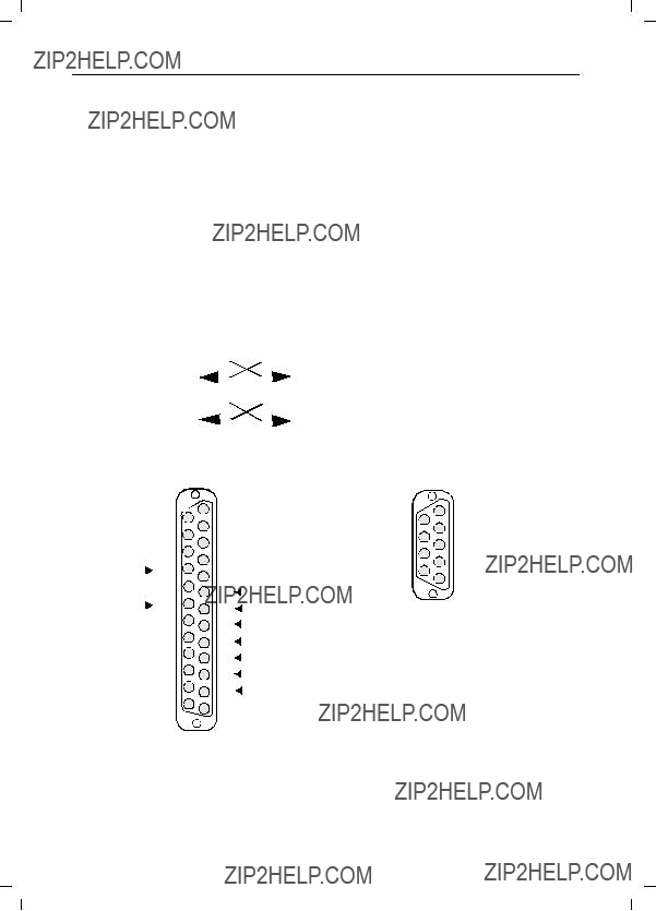
???The cable connections to the connected devices are fully in- serted and screwed in.

???The stations are not too far apart and are there are no large parts of buildings in between.

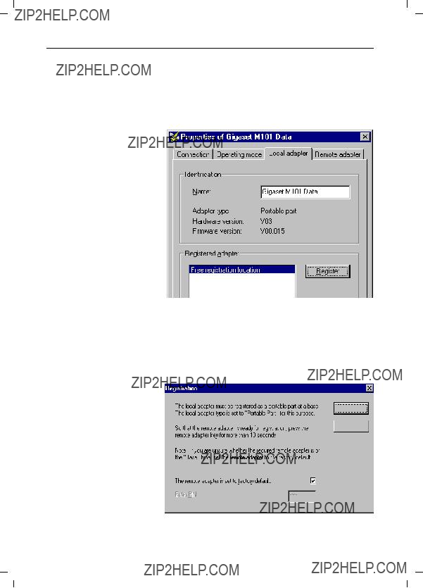
???Registration was successful.

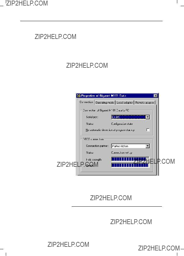
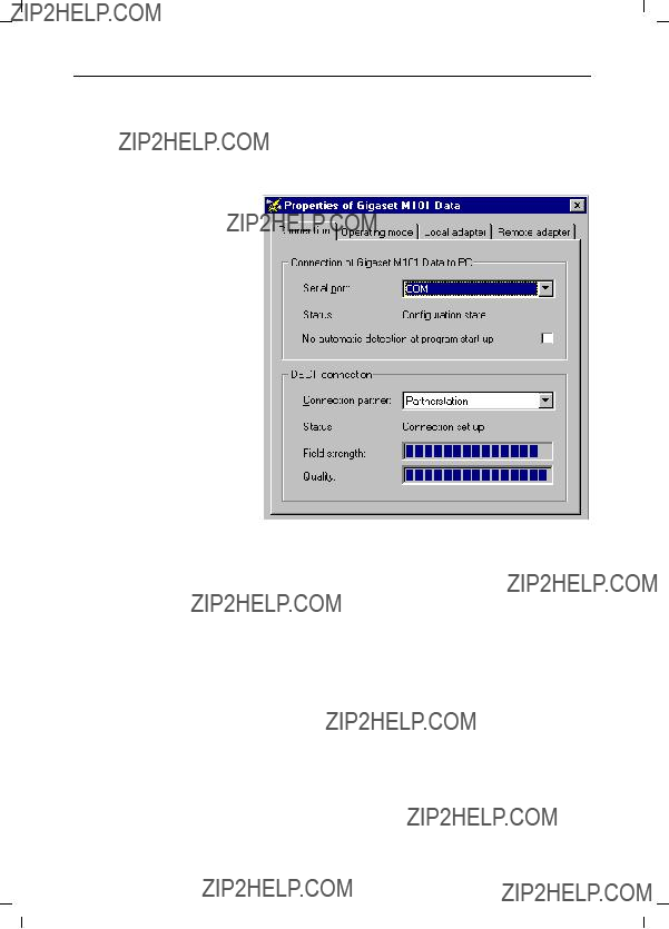
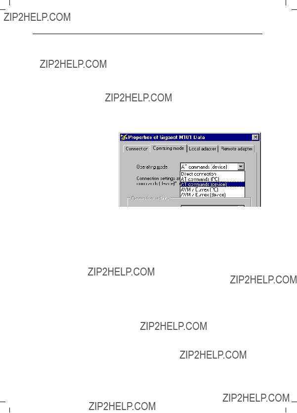
???The lokalen Station operating mode is "AT commands, local" or "AVM/Eumax commands, local".

or:

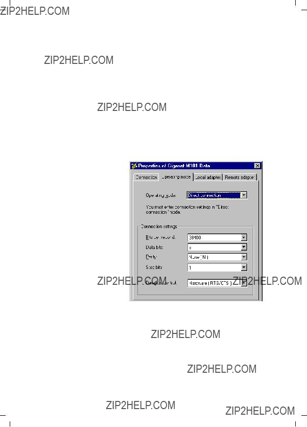
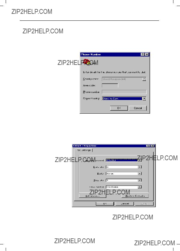
???The lokalen Station operating mode is "Direct connection" and you have set the direct connection transmission param- eters in your communication software.

If the malfunction still occurs after checking all the above points, reset both Gigaset M101 Data units to the factory defaults, see page 19.

If the malfunction persists, call the hotline at 0180 5 333 220.

Internet: www.siemens.de/gigaset

Notes on installation and operation

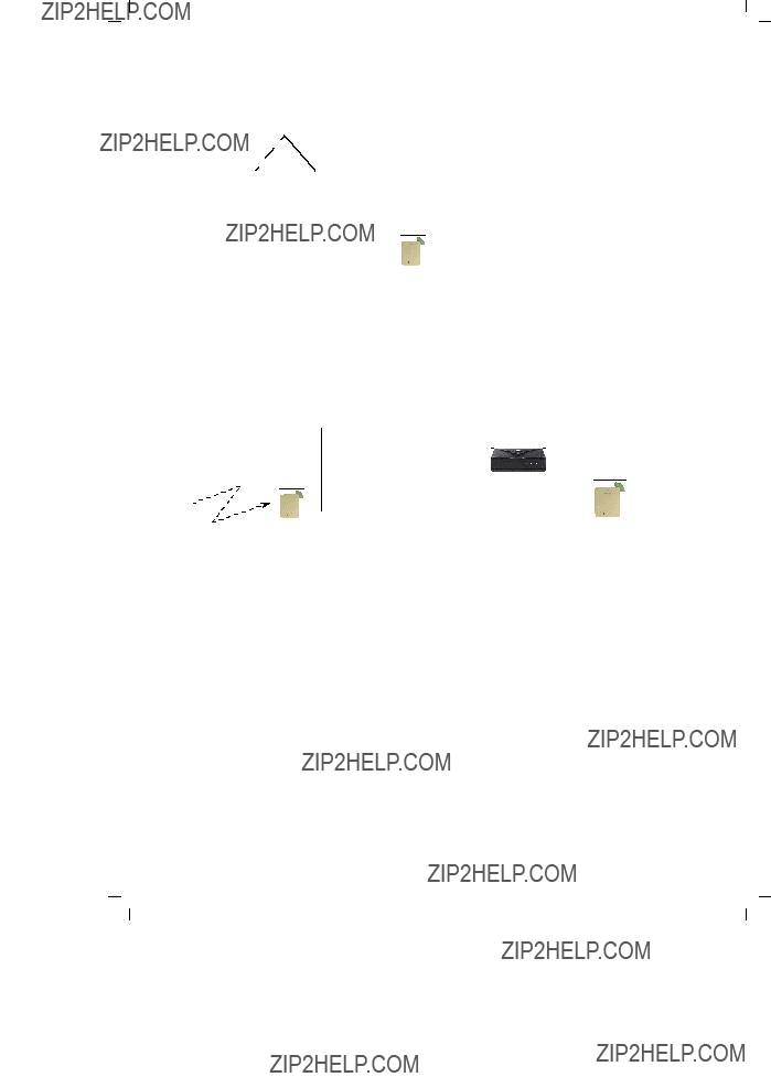
Place of installation

There must be a 220/230 V AC 50 Hz power socket in the vicin- ity.

The Gigaset M101 Data should not be installed in the immediate vicinity of other electronic devices, such as hi-fi systems, office equipment or microwave ovens, otherwise there is a risk of mu- tual interference.

Place the Gigaset M101 Data unit on a level, non-slip surface. The device feet do not normally leave any unsightly marks. How- ever, in view of the many different varnishes and polishes cur- rently used for furniture, the possibility of marks being left can- not be ruled out.

Radio communication between Basis and Teilnehmer is based on the DECT standard. The Gigaset M101 Data complies fully with the relevant European directives. Should you nevertheless experience sound or picture distortion with your satellite signal receiving equipment, please get in touch with your dealer to have it tested for shielding faults.

Depending on the ambient conditions, the maximum radio range between the local station and the Partnerstation is ap- prox. 300 m outdoors and approx. 50 m indoors.

20

What happens if...

Temperature and ambient conditions

The Gigaset M101 Data is designed for operation in protected rooms with a temperature range from +5??C to +45??C.

Do not set up the Gigaset M101 Data in damp environments, such as a bathroom or laundry room. Do not expose it to direct sunlight or other heat sources, such as radiators.

Technical data

21

The V.24 interface

22

Why set a mode? Technical background

Serial interfaces are more than plug-in connections. They have an integrated data flow control, control lines, data lines and an adjustable speed function. Serial interfaces are used for trans- porting data in various formats.

Modems are usually controlled with AT commands or company- specific protocols commands that they receive via their serial in- terface. On the basis of these AT or AVM/Eumex commands, modems can recognise the format and speed at which the data is transmitted. The automatic recognition of transmission pa- rameters is important and must be emulated by the radio link if a device that understands these commands is used for param- eter adjustment and is connected to the Partnerstation.

A cordless extension cable between a PC and, for example, a modem must detect the transmission parameters to be used at the PC interface for communication between this interface and the modem. On the modem side, the functions generated by the PC must also be created for the serial interface.

On the radio link, data is transferred according to a radio protocol that has nothing to do with the serial interface.

If a device which cannot detect transmission parameters in the same way as a modem is connected to the Partnerstation, "Di- rect connection" is selected as the operating mode.

There are thus five possible operating modes for each Gigaset

M101 Data:

1.Direct connection: this operating mode is implemented for all devices that are not controlled with AT or AVM/Eumex commands.

2.AT or AVM/Eumex commands, local: this is the operating

mode for the lokale Station: the local Gigaset M101 Data de- termines the conditions on the serial interface in the same way as a modem and transmits data as well as information to the Partnerstation on the transmission parameters to be used for entering this data in the terminal.

3.AT or AVM/Eumex commands, remote: in this operating mode, the Partnerstation controls a terminal that under- stands the AT commands.

23

Tips & tricks, settings

Tips & tricks, settings

This section describes settings, implementation options and programming methods.

Operating from a local station with two remote stations:

Please note that

???Only one connection can be active.

???Only one "Teilnehmer" station type can be registered at a base that is ready for registration.

???The station type for Gigaset M101 Data units is set to "Basis" by default.

Perform registration as described in the section "Initial configu- ration" on page 11.

The Gigaset unit connected to the PC is called "Gigaset 1" and is the lokale Station. It is now an Teilnehmer station type and your Gigaset 2 (Partnerstation) is a Basis. Configure the trans- mission parameters that are required for a connection between Gigaset 1 and Gigaset 2.

Change to the Local station tab and click Change station type, your Gigaset 1 is now a base.

Exit the configuration program and connect Gigaset 3 to the COM port.

Now start the "Gigaset M101 Data > Set Gigaset" configuration program and switch to the Local station tab. Click Change sta- tion type. Gigaset 3 is now an "Teilnehmer".

Press the black button on Gigaset 1 (station type currently Ba- sis) for 10 s. The LEDs start to blink alternately, the base is ready for registration.

Click Register, enter the PIN (factory default "0000") and click OK. You have now registered Gigaset 3 (as an extension) at Gigaset 1 (the base).

Configure the transmission parameters that are required for a connection between Gigaset 3 and Gigaset 1. Exit the configu- ration program.

Connect Gigaset 1 to the COM port at the PC that you want to use for bothway operation.

24

V.24

PC - PC direct cable connection: via RS232/V.24 interface

The problem that often occurs withPC - PC direct cable connec- tions is incorrect baud rate setting. The following section de- scribes how to configure a PC - PC direct cable connection at a Win951 system.

Before using the actual Gigaset M101 Data, application function- ality should be checked using a null-modem cable2. This accel- erates fault detection and clearance. If this is not possible, the precise configuration should be observed.

???Gigaset M101 Data can be set to a fixed baud rate (direct connection 115,200 bps with HW handshake).

25

Tips & tricks, settings

Setting the direct connection to the correct baud rate

1.Open the terminal program

The first step is to open a terminal program on both PCs (e.g. Win95 HyperTerminal via Hypertrm.exe) and to ensure that the correct COM port is being accessed,

Set up a direct connection via COMx (COM 1 is selected in the example).

Then set the interface speed:

26

Tips & tricks, settings

The baud rate (max. 115,200) and HW handshake (default setting) are set in this mask. If you are able to transmit data from one PC to the other, proceed now to the second step.

2.Set direct cable connection parameters

Exit the terminal program at one of the PCs. Select Settings > Control Panel in the Start list under Win95 to open the Control Panel window. Click the System icon (you should now see the System Properties window). Select the Device Manager tab. This folder contains a Modem icon;

double-click this icon to expand the branch. The setting Null- modem cable at COMx should be available. Select the ap- propriate COM port for your configuration and double-click it to open a further subfolder.

27

Tips & tricks, settings

You will find maximum speed setting in the Modem tab; this should be set to 115,200 bps.

Activate Hardware under Use flow control in the Settings -

Advanced tab. Click OK to exit each window.

3.Test the baud rate setting

Open the direct cable connection program via

Start > Programs > Accessories.

If this icon is missing, you may have to reinstall the appro- priate software from the Win 95 system CD.

This can be done by selecting Control Panel, Add/Remove Programs, Windows Setup, Communications, Details, Di- rect Cable Connection.

28

Tips & tricks, settings

Select Modify under Settings and activate Guest. Enter the port, e.g. ???Null-Modem Cable at COM 1???.

To enable access by the other PC, the host (controlling) and guest (accessing), as well as the file and print sharing option must be activated.

29

Tips & tricks, settings

Click File and Print Sharing in the sub-window.

Set the parameters here. If a modification was made, new drivers are loaded and Windows must be restarted.

If file and print sharing was already activated, the computer does not need to be restarted. Otherwise, restart your com- puter.

30

Tips & tricks, settings

If the computer was not restarted, the following window ap- pears:

If file/printer sharing has not yet been activated, you can activate this feature, see "Sharing files" on page 32.

In the final window, select Finish and click OK to answer the questions. You should now see a window titled Direct Cable Connection with the status Accessing %1!s.

The message CLIENT should appear a number of times in the terminal program of the connected PC.

If this is not the case, repeat this procedure on another PC.

If the message Client does not appear, try the following:

???Close the Direct Cable Connection window

???Activate the task manager via <CTRL> <ALT> <DEL>. Se- lect the task ???Rnaapp??? and end it by clicking End Task.

???Repeat step 2 and step 3.

If this is unsucessful, the problems may have a different source.

31

Tips & tricks, settings

Sharing files

Since the Windows information given in the previous mask is somewhat confusing, and since no references are made to the File Manager/Explorer, here is the correct procedure. Once file sharing has been activated and the PC restarted, you can re- lease files for processing by the other PC via the File Manager/ Explorer.

To do this, start up Windows Explorer

Select the appropriate folder and then click File1 > Properties. The following mask containing the tabs General and Sharing ap- pears:

Assign rights for the other PC users on your hard disk or set a password to prevent access.

Files that support sharing are identified as follows:

shared

not shared

1Error in Windows help: the Properties submenu is not de- scribed.

32

Tips & tricks, settings

PC - PC direct cable connection problems: examples

Other modem drivers installed continue to operate at the same COM port (special ISDN TA drivers, CAPI modem drivers or sim- ilar software are often the cause of the problem).

Once successfully put into service, you can start up the direct cable connection at both PCs. Remember that one PC must be set as host and the other as guest. Access to files should also be released via the settings Network/File and Print Sharing. Fi- nally, the subfolders to be accessed by the guest must be re- leased via the Explorer.

MAC and other operating systems

In general, Gigaset M101 Data can be implemented at every RS232/V.24 interface if data transfer is performed transparently and not on a company-specific basis (exception: AVM and Eumex) or with AT Hayes commands.

However, both Gigaset M101 Data units must first be config- ured and registered at a Windows 95/98/NT system. When pro- gramming a modem connection, ensure that the Gigaset M101 Data unit is connected to the correct device. To do this, we rec- ommend that you place a sticker, e.g. marked modem or PC, un- der the Gigaset M101 Data unit so that the correct device is con- nected later.

Meaning of "lokale Station" and "Partnerstation"

These designations are used for assigning names and indicating stations in data traffic. "Local station" refers to the station that undertakes all configuration operations (also for the "Partnersta- tion"). This means that in the case of a direct cable connection, Gigaset M101 Data setup does not have to be installed on the second PC.

Meaning of "Basis" and "Teilnehmer"

This is an assignment in DECT radio engineering (FP = fixed part, PP=portable part) and only applies to the air interface. "Base" is a Gigaset telephone base station. In this case, "Teilne- hmer" refers to a mobile unit. This is defined, for example, through the registration option. Only one Gigaset M101 Data "Teilnehmer" can be registered at a Gigaset M101 Data "Basis".

Meaning of local, remote

When "local" is set, the Gigaset M101 Data connected behaves like a modem/device and performs the PC COM port function.

When "remote" is set, the Gigaset M101 Data connected be- haves like a PC and performs the function of the connected de- vice.

33

Tips & tricks, settings

When "AVM/Eumex" is set, the special features of the AVM proprietary (company-specific) protocol are taken into consider- ation. In this case the speed settings are not compliant with AT Hayes commands.

Support

Updates and news on the Internet

www.siemens.com/pc-communication-support

Notes on sending faxes directly from the PC

You may encounter problems if your PC program uses Class 1 fax mode. Class 1 does not support any delays in signal runt- imes which are necessary for switching to radio mode.

Class 2 mode, on the other hand, is not as sensitive as Class 1. However, interference can still occur due to a bad radio link. If you have problems with this setting, start the configuration pro- gram and check the transmission quality under Connection. This can be changed by moving the Gigaset M101 Data unit slightly.

34

35

Tips & tricks, settings

36

Issued by

Information and Communication Products Hofmannstra??e 51, D-81359 M??nchen

?? Siemens AG 1999. All rights reserved. Subject to availability.

Right of modification reserved.

37