The FP22 is a battery-powered stereo headphone amplifier that provides headphone feeds from any audio input source. It has the unique capability of monitoring mono, stereo and mixed mono and stereo inputs. The FP22 monitors and combines these signals in the headphones without affecting the original signal. Stereo or mono headphone outputs appear on 1/4-inch phone or mini 3.5 mm stereo jacks. The FP22 can drive headphones to very loud levels. It is ideal for anyone in the broadcasting, sound reinforcement or audio recording fields who needs a flexible, high??quality head- phone monitor.

The FP22 is excellent for:

???Line checking applications

???Providing multiple headphone feeds

???On stage in-ear monitoring

???Boosting headphone circuits

???Headphone foldback in recording studios

???Practicing musical instruments or mixed vocals through headphones while monitoring a stereo source

Features:

???Exceptionally wide frequency response and dynamic range

???High-impedance bridging inputs do not load signal sources

???Capable of mixing mono and stereo inputs in headphone outputs

???Complete user control of headphone volume

???Loopthrough 1/4-inch stereo phone jacks (can be internally switched to become separate left and right inputs)

???30 dB pad for stereo line input to accommodate a wide range of line level sources

???Balanced loopthrough XLR connectors switchable from mic to line level

???Separate XLR volume control on pull-out control knob

Shure Brothers Incorporated

222 Hartrey Avenue

Evanston IL 60202-3696 U.S.A.

Model FP22 User Guide

???Overall headphone balance control

???Overall stereo/mono switch for headphones

???LED power indicator

???Powered by easily obtainable 9??volt alkaline battery or by external 12 to 24 Vdc power supply (such as Shure Model PS20 or PS20E)

???1/4-inch and 3.5 mm stereo headphone jacks

???Effectively shielded for low susceptibility to radio-frequency interfer- ence (RFI)

SPECIFICATIONS

Frequency Response (ref 1 kHz)

20 Hz to 20 kHz, +1, ??3 dB (stereo line input) 50 Hz to 18 kHz, +1,??3 dB (mono XLR input)

Equivalent Input Noise

??125 dBV (maximum gain; source resistance 150 ??; 20 Hz to 20 kHz)

Voltage Gain (at 1 kHz)

Total Harmonic Distortion

Less than 0.5% measured at ??8 dBV into 8 ?? (20 Hz to 20 kHz stereo line input; 50 to 18 kHz mono XLR input)

Input Clipping Levels (at 1 kHz)

Mic level . . . . . . . . . . . . . . . . . . . . . . . . . . . . 160 mV (??16 dBV)

Line level . . . . . . . . . . . . . . . . . . . . . . . . . . . . . . 50 V (+34 dBV)

Output Level at Clipping

Input Impedance

XLR (mic level) . . . . . . . . . . . . . . . . . . . . . . . . . . . . 6.3 k?? ??10% XLR (line level) . . . . . . . . . . . . . . . . . . . . . . . . . . . . . 66 k?? ??10% Stereo Line (pad at 0) . . . . . . . . . . . . . . . . . . . . . . . 50 k?? ??10% Stereo Line (pad at 30 dB) . . . . . . . . . . . . . . . . . . . 53 k?? ??10%

Headphone Output Impedance (at 1 kHz)

10.2 ?? ?? 10%

Phase

Input in phase with output. Pin 2 of XLR input in phase with tip and ring of all Headphones jacks.

Power

Internal . . . . . . . . . . . . . . . . . . . . . . . One 9 V alkaline battery Battery Life . . . . . . . . . Approximately 15 hours under normal operating conditions External . . . . . . . . . . . . . . . . . . . . . . . . . . . . . . . . 12 to 24 Vdc

Current drain (typical) . . . . . . . . . . . . . . . 11 mAdc; 80 mAdc (clipping) at 9 Vdc
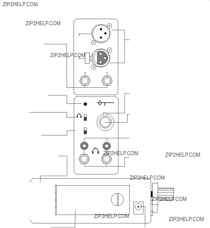
Connectors

Loopthrough

Two 3-pin balanced XLR-type connectors (one male, one fe- male)

Two 1/4-inch stereo phone jack (tip-left; ring-right; sleeve-

ground) Headphones

Two 1/4-inch stereo phone jack headphone outputs Two 3.5 mm stereo mini jacks

Power

6.5 mm coaxial power connector (tip +, sleeve ??)

Case

Die-cast zinc; matte black enamel finish

Overall Dimensions

80.9 mm H x 55.5 mm W x 153 mm D (3-3/16 x 2-3/16 x 6-1/16 in.)

Net Weight

450 grams (1 lb)

NOTE: The FP22 is lightweight and can be clipped to a belt or trousertop, or to D-rings on other equipment. The FP22 belt clip is attached to the case with two easily removable screws. The FP22 will stand on a flat surface, and several units can be stacked together with their belt clips removed.

SETUP

Battery Replacement

1.Use a coin or screwdriver to turn the 1/4-turn lockscrew fasten- er in either direction to open the battery compartment door.

2.Insert a fresh 9??volt alkaline battery (NEDA 1604A, Duracell MN1604A, Eveready 522, or equivalent) in the compartment. The battery compartment is designed so that the polarized bat- tery terminals cannot be inserted incorrectly. Plated spring ter- minals ensure solid electrical contacts.

External Power

The coaxial dc power jack accepts a dc voltage from 12 to 24 volts. External dc power feeds a regulator to power the FP22 cir- cuitry. The dc input jack is directly compatible with Shure Model PS20 or PS20E Power Supplies. The tip of the coaxial jack is positive (+), the sleeve is negative (??). A coaxial power plug in- serted into the external power jack disables the internal battery power.

Signal Connections

Mono XLR??Microphone?? or line??level signals

1.Set the Mono XLR Mic-Line switch to the appropriate signal level.

2.Connect a balanced microphone or line level signal to either Mono XLR jack.

3.If loopthrough is desired, use the unused XLR connector as an output.

NOTE: No damage will result if the Mic-Line switch is set incorrectly. However, objectionable distortion may result if line level signals are monitored with the switch in the Mic position.

Stereo Line??Line?? or Aux??level signals only

1.Connect a 1/4-inch stereo connector to either Stereo Line jack.

2.If loopthrough is desired, use the unused 1/4-in. stereo con- nector as an output.

3.Set the front panel Stereo Line Pad to the 0 dBm line??level signal position. The ??30 dB position is used when the FP22 line??level input signals are +4 dBm or greater.

NOTE: As explained in the Internal Switches description, the FP22 can accept left and right input signals on separate con- nectors. Stereo Line jack (1) is left, Stereo Line jack (2) is right.

Headphones

1. Connect headphones to the Headphones A and B jacks. NOTE: Each pair of Headphones jacks consists of one 1/4-inch

and one 3.5 mm stereo connector. Only one connector of each pair can be used at one time. Plugging into the 1/4-inch connector disconnects its associated 3.5 mm connector.

OPERATION

NOTE: A simplified block diagram on the side of the FP22 pro- vides a quick reference to its functional circuitry.

1. Rotate the overall Volume control clockwise to power the FP22. The Power LED indicator lights to show that the unit is on. Turn the level control carefully to avoid excessive head- phone levels. The Volume control adjusts both the Mono XLR signal and Stereo Line signal.

WARNING

The FP22 can produce ear??damaging headphone levels. Turn the headphones Volume control up slowly when making adjustments.

2.Pull out the Volume control knob and rotate clockwise to in- crease the volume level of the Mono XLR signal only. This ad- justment will not affect the overall volume. A center detent posi- tion provides a starting volume level for the Mono XLR signal.

3.Rotate the Balance control left or right to control the overall left/ right signal balance.

4.If mono monitoring is desirable, set the Stereo/Mono switch to Mono.

INTERNAL SWITCHES

Two switches are located inside the FP22. These control the signal path through the unit. The switches are located on the ver- tically mounted printed circuit board inside the unit adjacent to the Loopthrough phone jacks. To access the switches, remove the three Phillips-head screws on the side panel of the unit.

Internal Switch S-104 consists of two independent single- pole, single??throw switches controlling the path of the Mono XLR input signal:

1.When S104-1 and -2 are in the On position, the Mono XLR sig- nal is routed to both left and right earphones.

2.When S104-1 is in the On position and S104-2 is in the Off position, the Mono XLR signal goes to the left channel.

3.When S104-1 is in the Off position and S104-2 is in the On position, the Mono XLR signal goes only to the right channel.

4.If both S104-1 and -2 are in the Off position, NO signal from the Mono XLR input appears at the headphone outputs.

Internal Switch S105 is a two??position slide switch that

changes the Stereo Line jacks from Loopthrough TRS stereo in- puts to separate left and right mono inputs.

1. When internal switch S105 is set for stereo, the Stereo Line jacks accept a stereo signal on a single 1/4-inch stereo connector (tip- left; ring-right; sleeve-ground). This allows for a loopthrough of a

2

stereo signal since both 1/4-inch Stereo Line jacks are connected in parallel.

2. When internal switch S105 is set for Mono, the FP22 accepts individual left and right 1/4-inch mono connectors to provide a stereo signal. Stereo Line jack (1) is the left input; Stereo Line jack (2) is the right input. No loopthrough capability is available with S105 set for Mono.

TYPICAL MONITORING CONNECTIONS

1.One Mono Input. A mono signal connected to an XLR or phone jack will be monitored as a mono headphone signal. (When using the Mono XLR connectors, the Line/Mic switch should be set to match the input.)

2.One Stereo Input. A stereo signal connected to the Stereo Line jacks can be monitored as a stereo output on stereo head- phones or as a mono output.

3.One Stereo Input Plus One Mono Input. A mono signal input through the Mono XLR connector and a stereo signal input through the Stereo Line jacks can be monitored as a mixed out- put, with both signals appearing in the stereo headphones.

4.Three Mono Inputs - Stereo Headphone Signal Output.

Three mono signals can be accepted through the mono-XLR jacks and the stereo line jacks, and mixed and monitored as a stereo signal in the stereo headphones.

NOTE: The FP22 can be modified so that all input jacks are in parallel. This duplicates the Shure FP12 in functionality. This modification allows monitoring in mono only. Please contact Shure's Product Applications Group for details on this modifi- cation.

INTERCOM CAPABILITY

The FP22 can interface to commercially available intercom systems, such as RTS, Telex and ClearCom. The diagrams be- low show how to interface the FP22 to these systems and what can be monitored. More information about intercom systems can be obtained from the intercom manufacturers.

Telex Intercom Systems (Figure 1)

Telex uses a standard balanced audio line. No modification is required to interface the FP22 with Telex intercoms.

1.Use the Mono XLR Loopthrough connections.

2.Mono XLR level switch should be set to the Line position.

3.24 volts phantom power on the intercom line is passed through the FP22.

REF

FIGURE 1

RTS and ClearCom Systems (Figure 2)

These two systems use an unbalanced audio line which re- quires use of the 1/4-inch line connectors of the FP22 for opera- tion. The Y??cable depicted in Figure 2 is required for RTS and ClearCom intercom systems.

1.The above Y??cable is placed in-line into the intercom system.

2.Set internal switch S105 to Stereo (factory setting).

Wiring for RTS and ClearCom Systems

FIGURE 2

SPECIAL APPLICATIONS

Troubleshooting stage sound systems. The FP22 can be used to trace a signal line when one or more microphones are not working on stage. To locate the malfunction, loop the signal through the FP22 wherever an XLR or phone connector is lo- cated and monitor the signal.

Field monitoring applications can be set up by inserting FP22 units ??in line?? without affecting the signals.

On stage monitoring. With the FP22, an effective on??stage in-ear monitor system can be created. From a mixing console a stereo signal can be looped through to multiple FP22's, while the Mono XLR jack can be used for an individual's microphone or musical instrument. Each performer has control of overall head- phone volume as well as a mix control of their individual voice or instrument with the stereo signal.

Boosting headphone output. The FP22 can be used to boost the headphone output of existing devices. The stereo headphone output of an audio device can be connected to the Stereo Line connectors of the FP22. The FP22 will provide a high??quality headphone output with the ability to loop through to another FP22.

Using the FP22 as a two-stage intercom system. A two- stage intercom system can be created by connecting two FP22 units with a single standard microphone cable. Each person con- nects a Shure SM12A or other headset microphone's XLR output and earphone input connector to their individual FP22. Both mi- crophone signals appear at each FP22 headphone output.

Practice headphone amplifier for microphones or other sources, such as electric instruments, synthesizers, etc. Con- nect the output from any instrument into the FP22 and monitor the headphones.

3

Stereo Line Jacks

(Unbalanced) Dual function jacks. Factory supplied so that tip, ring, sleeve stereo signal applied to one jack can be looped through to other jack (tip-left, ring-right, sleeve-ground). Jacks can be in- ternally switched so that two mono phone jacks can be input and monitored in stereo without loopthrough (see Internal switches).

Mono XLR Connectors

(Balanced) Loopthrough connec- tors accept both mic and line level signals. Volume adjusts with pull out triple??function Volume control (center detent is nominal volume).

LED Power Indicator

Lights when FP22 is turned on.

Stereo/Mono Headphone Mode

Switch

Changes headphones from stereo to mono. Especially useful when monitoring monaural signal con- nected to stereo line jacks.

Stereo Line Pad

Reduces gain on Stereo Line sig- nals by 30 dB. Especially useful with signal levels of +4 dBm or greater.

Mono XLR Mic/Line Switch

Selects between microphone and line level signals coming into XLR connector (50 dB pad inserted be- fore mic preamp when switch is in Line position).

Battery Compartment

Requires one 9 V alkaline battery.

12??24 Vdc

IN

?? +

External Power Jack

Accepts external supply voltage from 12 to 24 Vdc (such as Shure PS20 or PS20E Power Supplies). Tip is positive, sleeve is negative.

4

REPLACEMENT PARTS LIST

*Commercial alternates are acceptable equivalents; for optimum performance, only direct replacement parts should be used.

5