Model 514B User Guide

GENERAL

The Shure 514B is a low impedance, dynamic, hand-held microphone designed for paging and public address sys- tems. It provides clear, natural voice response and high in- telligibility.

The 514B connects to microphone inputs rated at 19 to 300 ??? . It can be used in applications that require long cable lengths, or where severe hum conditions are present. For connection to high impedance inputs, use Shure A95 Series Line Matching Transformers.

The microphone is provided with a four-conductor (two shielded) coiled cable and a ???Million-Cycle??? leaf-type switch designed for constant use under the most rigorous condi- tions. The 514B fits naturally and comfortably in the hand and is not affected by heat or humidity. The exclusive ARMO-DURR case resists mechanical shocks and vibra- tion, and is impervious to oil, fumes, salt spray, ultraviolet radiation, and corrosion.

Features

???Smooth, extended frequency response from 100 to 6,000 Hz???provides highly intelligible voice response

??????Million-Cycle??? leaf-type switch???provides outstanding reliability, even under extreme conditions

???Tough ARMO-DURR case

???Long-life, neoprene-jacketed, coiled cable

???Supplied mounting bracket fits hang-up button on back of microphone

CONNECTIONS

Refer to Figure 1 and Table 1 below. The GREEN wire is connected to the positive audio input, the WHITE wire is con- nected to the negative audio input, and the SHIELD is con- nected to chassis ground. The RED and BLACK leads con- trol the external relay or switching circuit.

INTERNAL CONNECTIONS

FIGURE 1

Table 1. Typical Cable-to-Connector Wiring

NOTE: The RED and BLACK leads are not part of the audio circuit. These wires provide a contact closure when the press-to-talk switch is depressed. This closure may be used to control an external relay or a transmit/receive circuit.

OPERATION

To operate the microphone, simply hold down the press
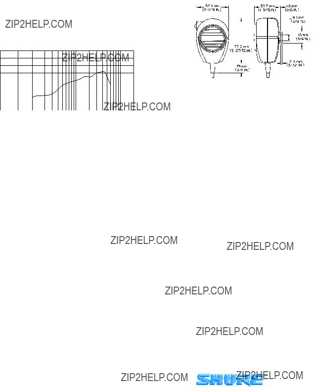
- to-talk switch and begin speaking. Release the switch when you are finished speaking.

MOUNTING

The 514B is supplied with a mounting bracket to provide a snap-in hang-up for the microphone when it is not in use. The bracket has mounting holes with clearance for No. 8 screws. See Figure 2 below.

MOUNTING BRACKET

FIGURE 2

??? 2002, Shure Incorporated

27B1387 (BJ)

Printed in U.S.A.

SPECIFICATIONS

Type

Dynamic

Frequency Response

100 to 6,000 Hz (see Figure 3)

+10

Hz

TYPICAL FREQUENCY RESPONSE

FIGURE 3

Impedance

Microphone rating impedance is 150 ??? (200 ??? actual) for connection to microphone inputs rated at 19 to 300 ??? .

Output Level

Open Circuit Voltage . . . . . . . . . . . . ???36.5 dB (15 mV)* ???56.5 dBV/Pa (1.5 mV)**

*0 dB = 1 volt per 100 microbars

**1Pascal = 94 dB SPL

Switch

Push-to-talk, leaf-type switch to actuate microphone circuit and relay or switching circuit. Microphone circuit normally open.

Cable

1.5 m (5 ft) extended, four-conductor, two-conductors shielded, neoprene-jacketed, coiled cable

Case

Matte black ARMO-DURR

Dimensions

See Figure 4

OVERALL DIMENSIONS

FIGURE 4

Net Weight

200 grams (7 oz)

Packaged Weight

372 grams (13 oz)

CERTIFICATION

Conforms to European Union directives, eligible to bear CE marking; meets European Union EMC Immunity Re- quirements (EN 50082???1, 1992).

FURNISHED ACCESSORY

Mounting Bracket (3 in kit) . . . . . . . . . . . . . . . . . . . RK6MB

OPTIONAL ACCESSORY

Line Matching Transformer . . . . . . . . . . . . . . . A95 Series

REPLACEMENT PARTS

Dynamic Cartridge . . . . . . . . . . . . . . . . . . . . . . . . . . . R103

Switch . . . . . . . . . . . . . . . . . . . . . . . . . . . . . . . . . . . . . RK15S

Cable Assembly . . . . . . . . . . . . . . . . . . . . . . . . . . . . . . C25C

SHURE Incorporated Web Address: http://www.shure.com 5800 W. Touhy Avenue, Niles, IL 60714-4608, U.S.A. Phone: 800-257-4873 Fax: 847-866-2279

In Europe, Phone: 49-7131-72140 Fax: 49-7131-721414

In Asia, Phone: 852-2893-4290 Fax: 852-2893-4055

Elsewhere, Phone: 847-866-2200 Fax: 847-866-2585