Ver. 6.0U _ Sep 6, 2012
INSTALLATION AND USER MANUAL
FOR SHARP PHOTOVOLTAIC MODULES
ND-255QCS / ND-250QCS / ND-245QCS
ND-250QCJ / ND-245QCJ / ND-240QCJ
ND-Q250F7 / ND-Q245F7
IMPORTANT SAFETY INSTRUCTIONS
PLEASE READ THIS MANUAL CAREFULLY BEFORE INSTALLING OR USING THE MODULES.
PLEASE PASS ALONG THIS MANUAL TO YOUR CUSTOMER.
A) GENERAL MANUAL
A-1. INTRODUCTION
Thank you for choosing SHARP photovoltaic (PV) module. This Installation Manual contains essential information for electrical and mechanical installation that you must know before installing SHARP photovoltaic modules. These modules are listed to standard UL 1703. This Manual also contains safety information you need to be familiar with. All the information described in this Manual is the intellectual property of SHARP and is based on the technologies and experience that have been acquired and accumulated over the long history of SHARP. This Manual does not constitute a warranty, expressed or implied. SHARP does not assume responsibility and expressly disclaims liability for loss, damage, or expense arising out of or in any way connected with installation, operation, use or maintenance of PV modules. No responsibility is assumed by SHARP for any infringement of patents or other rights of third parties that may result from use of PV modules. SHARP reserves the right to make changes to the product, speci???cations or Installation Manual without prior notice.
A-2. GENERAL INFORMATION
(INCLUDING WARNING AND SAFETY)
The installation of PV modules requires a great degree of skill and should only be performed by quali???ed licensed professionals, including licensed contractors and licensed electricians. Please be aware that there is a serious risk of various types of injury occurring during the installation including the risk of electric shock. These SHARP PV modules are equipped with a permanently attached special cable assembly for ease of installation which does not require special assembly.
<GENERAL WARNING >
1.PV modules are heavy. Handle with care.
2.Before you attempt to install, wire, operate and maintain the PV module, please make sure that you completely understand the information described in this Installation Manual.
3.Contact with electrically active parts of a PV module such as terminals can result in burns, sparks and lethal shock whether the PV modules are connected or not.
4.PV modules produce electricity when suf???cient sunlight or other light source illuminates the module. When modules are connected in series, voltage is cumulative. When modules are connected in parallel, current is cumulative. PV systems can produce high voltage and current which could present an increased hazard and may cause serious injury or death.
5.Do not connect PV modules directly to motor loads. Variation in PV module output power as a function of solar irradiance may damage directly-connected loads. For example,
1:In the case of a brushless motor, the lock function may become active and the motor may be damaged;
2:In the case of a brush type motor, the coil may be damaged.
6.Always use gloves when handling the module, never touch the glass surface with bare hands.
<GENERAL SAFETY >
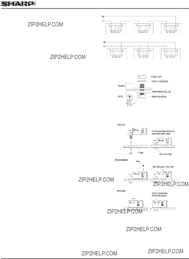
1.Wiring and grounding method of the frame of arrays shall comply with national, regional and local codes, laws and standards.
2.PV modules should be installed and maintained by quali???ed personnel. Only installation/service personnel should have access to the PV module installation site.
3.Keep children away from PV modules.
4.Prior to installation, do not store modules outdoors or in a damp environment to prevent glass from damage due to white ef???orescence.
5.When PV modules are installed on roofs or any other structures
above ground, appropriate safety practices should be followed and appropriate safety equipment should be used in order to avoid possible safety hazards. Note that the installation of PV modules on some roof types may require the addition of ???reproo???ng, as required by local building/???re codes.
6.Roof mounted PV modules are to be mounted over a ???re resistant roof.
7.Only PV modules with the same cell size should be connected in series.
8.Follow all safety precautions of other components used in the system.
9.In order to avoid risk of injury or electrical shock, do not allow anyone to handle damaged PV modules if the person is unquali???ed or has limited knowledge of PV modules. Place defective PV modules in cartons so PV cells are completely shaded, because a defective PV module or module with broken glass may generate power even if it is removed from the system.
10.Avoid uneven shade on the PV module surface. Shaded cells may become hot (???hot spot??? phenomenon) which may result in permanent damage to the module (e.g., solder joints may peel off).
11.Do not clean the glass surface with chemicals. Do not let water stay on the glass surfaces of PV modules for a long time. This creates a risk of permanent damage to the glass, such as white ef???orescence, otherwise known as ???glass disease,??? which may cause reduced power output.
12.To avoid dirt accumulation or white ef???orescence due to water accumulation, do not install PV modules horizontally (???at).
13.In case of snow build up, snow would be slide down easier on the module than other parts of the roof. When snow suddenly slide and fall off the module???s surface, it may fall to under the roof and reach nearby areas. Ensure that the installment of the modules would not cause any damage to objects (carport, bicycle, entrance) nearby. Apply appropriate safety measures and/or safety equipments (e.g. snow stopper) when necessary.
14.Do not expose PV modules to sunlight concentrated with mirrors, lenses or other means.
15.Turn off inverters and circuit breakers immediately, should a problem occur.
16.The maximum open circuit voltage must not be greater than the speci???ed maximum system voltage. Voltage is proportional to the number of PV modules in series and is affected by weather conditions. For strings connected in parallel take proper measures to block reverse current ???ow.
Ver. 6.0U _ Sep 6, 2012
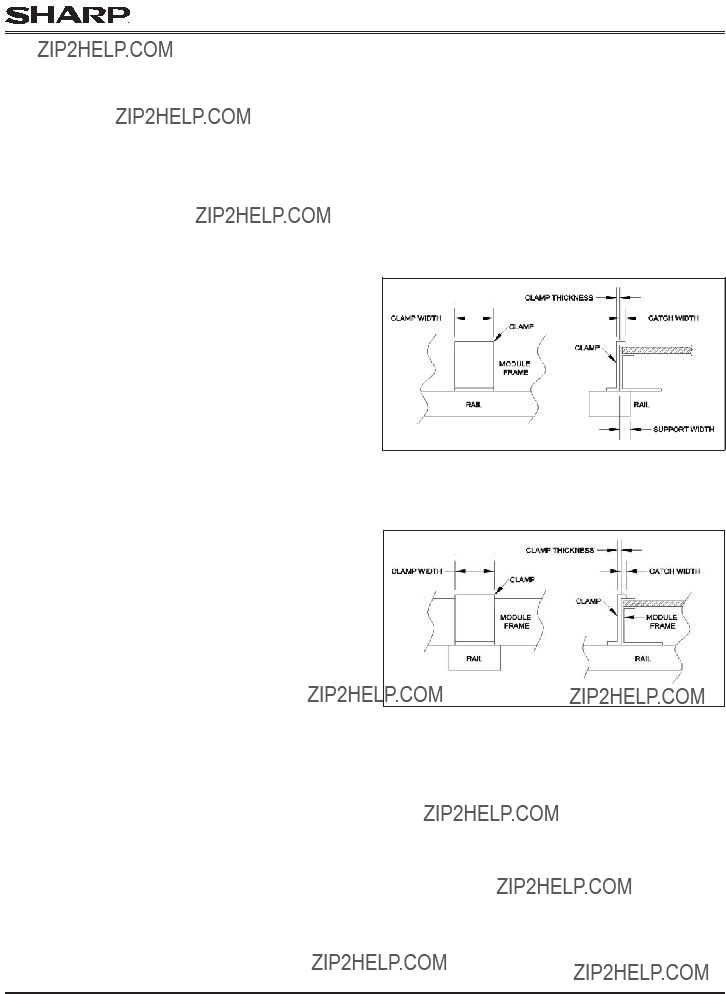
Mounting using Clamps on Long Edge of Module (Figure 7) ??? 2 Clamp Method
The modules may be mounted using clamps designed for solar modules as shown in Figure 7. Note the clamp position is important. The 22??? length clamp should be positioned so that it supports the center of each long frame of the solar module. The clamp should be af???xed to the modules and mounting structure with 4 bolts on each long frame. For the 2 clamp mount method, the minimum clamp length dimension is 22???. The modules should be inserted fully into the module clamps so that the outside edge of the module frame is ???ush with the inside surface of the clamp. The clamp is designed to overhang the top module edge by 12mm. This mounting method is designed to allow module loading of 1,440 Pa.
C) ELECTRICAL INFORMATION
ELECTRICAL RATINGS
Rated electrical characteristics are within ??10 percent of the indicated values of Isc, Voc and within +5/-0 percent of Pmax under Standard Test Conditions (irradiance of 100 mW/cm2, AM 1.5 spectrum, and a cell temperature of 25??C (77??F)). The warranty conditions are speci???ed elsewhere in this manual.
Under normal conditions, a PV module may produce more current and/or voltage than reported at Standard Test Conditions. Accordingly, the values of Isc and Voc marked on UL 1703 listed modules should be multiplied by a factor of 1.25 when determining component voltage ratings, conductor ampacities, fuse sizes and size of controls connected to the module output. Refer to Sec. 690-8 of the National Electrical Code for an additional multiplying factor of 125 percent (80 percent de-rating) which may be applicable. Where Canadian UL listing applies, installation shall be in accordance with CSA C22.1, Safety Standard for Electrical Installations, Canadian Electrical Code, Part 1.
Ver. 6.0U _ Sep 6, 2012
USER MANUAL
IMPORTANT SAFETY INSTRUCTIONS
This manual contains important safety instructions for the PV module that must be followed during the maintenance of PV modules.
1)To reduce the risk of electric shock, do not perform any servicing unless you are quali???ed to do so.
2)The installation should only be performed by quali???ed licensed, professionals, including licensed electricians and lisensed contractors. To ensure system integrity and safety
3)Do not pull the PV cables.
4)Do not touch any surface of module.
5)Do not place/drop objects onto the PV modules.
6)Do not disassemble or attempt to repair the PV module by yourself.
7)Do not drop the PV module.
8)Do not damage, pull, bend, or place heavy material on cables.
9)Upon completion of any service or repairs, ask the installer/servicer to perform routine checks to determine that the PV modules are in safe and proper operating condition.
10)When replacement parts are required, be sure the installer/servicer uses parts speci???ed by the manufacturer with same characteristics as the original parts. Unauthorized substitutions may result in ???re, electric shock, or other hazard.
11)Consult your local building and safety department for required permits and applicable regulations.
12)Sharp modules use special materials to enhance energy harvest. Do not touch the module surface with bare hands. If ???nger prints are left on the module glass surface, do not attempt to clean them, ???nger prints will disappear over time.
SHARP ELECTRONICS CORPORATION
PHOTOVOLTAIC MODULE LIMITED WARRANTY
This Limited Warranty applies to photovoltaic modules manufactured by SHARP shown in this manual.
Limited Warranty For Materials or Workmanship: Sharp Electronics Corporation warrants to the ???rst consumer purchaser that this Sharp brand product (the ???Product???), when shipped in its original container, will be free from defective workmanship and materials, and Sharp agrees that for a period of ten (10) year from the date of purchase by the consumer, that Sharp will, at its option, either repair the defect or replace the defective Product or part thereof with a new or remanufactured equivalent at no charge to the purchaser for parts or labor for the period(s) set forth below.
Limited Warranty For Power: The warranty period with respect to power output continues for a total of 25 years from date of purchase by the consumer, the ???rst 10 years at 90% minimum rated power output and the balance of 15 years at 80% minimum rated power output. This warranty is transferable when product remains installed in original location at the time of product warranty registration.
This warranty does not apply to any alteration of the appearance of the Product that does not affect the performance or functionality of the Product, nor to the additional excluded item(s) set forth below nor to any Product, in Sharp???s sole discretion, the exterior of which has been damaged or defaced, which has been subjected to misuse, abnormal service or handling, or which has been altered or modi???ed in design or construction.
In order to enforce the rights under this limited warranty, the purchaser should follow the steps set forth below and provide proof of purchase to the servicer.
The limited warranty described herein is in addition to whatever implied warranties may be granted to purchasers by law. ALL IMPLIED WARRANTIES
INCLUDING THE WARRANTIES OF MERCHANTABILITY AND FITNESS FOR USE ARE LIMITED TO THE PERIOD(S) FROM THE DATE OF THE PURCHASE SET FORTH BELOW. Some states do not allow limitations on how long an implied warranty lasts, so the above limitation may not apply to you.
Neither the sales personnel of the seller nor any other person is authorized to make any warranties other than those described herein, or to extend the duration of any warranties beyond the time period described above on behalf of Sharp.
The warranties described herein shall be the sole and exclusive warranties granted by Sharp and shall be the sole and exclusive remedy available to the purchaser. Correction of defects, in the manner and for the period of time described herein, shall constitute complete ful???llment of all liabilities and responsibilities of Sharp to the purchaser with respect to the Product and shall constitute full satisfaction of all claims, whether based on contract, negligence, strict liability or otherwise. In no event shall Sharp be liable, or in any way responsible, for any damages or defects in the Product which were caused by repairs or attempted repairs performed by anyone other than an authorized servicer. Nor shall Sharp be liable or in any way responsible for any incidental or consequential economic, property or special damage. Some states do not allow the exclusion of incidental or consequential damages, so the above exclusion may not apply to you.
THIS WARRANTY GIVES YOU SPECIFIC LEGAL RIGHTS. YOU MAY ALSO HAVE OTHER RIGHTS, WHICH VARY FROM STATE TO STATE.
Ver. 6.0U _ Sep 6, 2012
Additional Item(s) Excluded from Warranty Coverage
Warranty coverage does not apply when:
a)The product is installed or repaired or serviced in a manner that is contrary to Sharp???s Installation Manual;
b)The product is installed in a mobile or marine environment,
c)The product is subjected to improper voltage or power surges or abnormal environmental conditions (such as acid rain or other pollution);
d)The components in the construction base on which the module is mounted are defective;
e)External corrosion, mold discoloration or the like occurs;
f)The product has been moved from its original installation;
g)The model number or serial number of the product is altered, removed or rendered illegible.
Sharp???s aggregate liability in connection with the Product, if any, shall not exceed the purchase price paid to Sharp for the Product or service which gave rise to the claim under the Limited Warranty.
The repair, replacement of the Product, or the supply of additional Product does not cause the beginning of new warranty terms, nor shall the original warranty terms of this Limited Warranty be extended. Any replaced product shall become Sharp???s property
Where to Obtain Service: Warranty service is available at a Sharp Authorized Service Center Dealer located in the United States. To ???nd the location of the nearest Sharp Authorized Service Center Dealer, call Sharp toll free at 1-800 SOLAR06 (800-765-2706).
Call toll free at 1-800-765-2706 to obtain a Return Authorization Number and shipping instructions. Proof of
Purchase will be required.
What to do to Obtain Service: Ship prepaid your Product to a Sharp Authorized Service Center Dealer. Be sure to have Proof of Purchase available. If you ship the Product, be sure it is insured and packaged securely. Sharp will not be responsible for damage incurred during transport.
SHARP ELECTRONICS CORPORATION
Sharp Plaza, Mahwah, New Jersey 07495-1163
TINSEA120MNZZ


 e
e  16.1??? (410 mm)