Quadpack QP 3041
Bedienungsanleitung
Instruction Manual
Notice d???emploi
1
Quadpack QP 3041
Bedienungsanleitung
Instruction Manual
Notice d???emploi
1
2

BEDIENUNGSANLEITUNG
Quadpack QP 3041
3
Sie haben die richtige Wahl getroffen!
Dieses
Nehmen Sie sich nun ein paar Minuten Zeit, um diese Anleitung zu lesen. Wir m??chten, dass Sie einfach und schnell in den Genuss dieser Technik kommen.
4
Verwendungszweck
Sie k??nnen bis zu vier Empf??nger EK 3041 in das Quadpack QP 3041 ein- setzen. Zusammen mit den dazugeh??renden Sendern erhalten Sie eine kom- pakte und mobile
Die empfangenen Audiosignale stehen an den
Sie k??nnen zwei Quadpacks kaskadieren und mit einem einzigen Antennen- paar betreiben.
Damit eignet sich das Quadpack f??r eine hochwertige kabellose
Sicherheitshinweise
??ffnen Sie niemals das Ger??t. Arbeiten an stromf??hrenden Teilen m??ssen immer vom Fachmann ausgef??hrt werden. Die Gew??hrleistung erlischt f??r Ger??te, die eigenm??chtig vom Kunden ge??ffnet wurden.
Halten Sie Abstand zu Heizungen und Heizstrahlern. Stellen Sie das Ger??t nie direkt in die Sonne.
Zum Reinigen gen??gt es v??llig, das Quadpack hin und wieder mit einem leicht feuchten Tuch abzuwischen. Verwenden Sie bitte auf keinen Fall L??se- oder Reinigungsmittel.
Lieferumfang
1 Quadpack
4 Teleskopantennen
4 F????e zum Ankleben
1
4 Schachtabdeckungen
1 Bedienungsanleitung
5
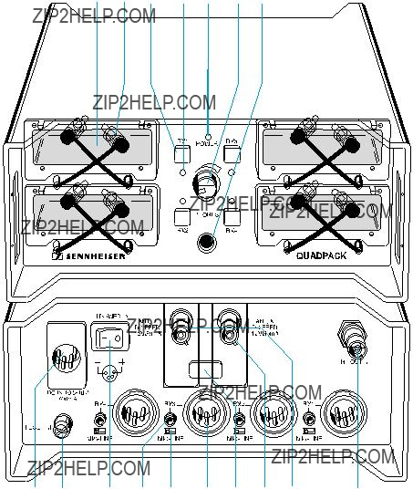
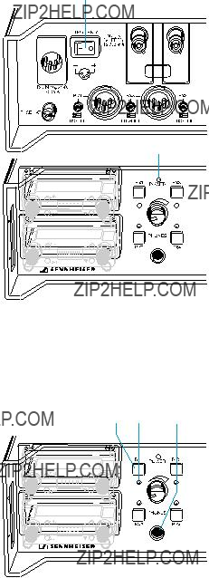
Bedienelemente
A B C D E F G
H I J K L M N O P Q
A Schacht f??r Empf??nger EK 3041 (4 x)
B
C
D
E Betriebsanzeige, rote LED
F Lautst??rkesteller f??r den Kopfh??rer
G Kopfh??reranschluss
H
J
K Steller f??r Ausgangspegel (4 x)
L Umschalter f??r Ausgangspegel (MIC/LINE, 4 x) M
O Eingangsmodul mit
6
Inbetriebnahme
Ger??tef????e unterkleben
Damit das Ger??t rutschfest auf einer Unterlage steht, liegen vier selbstkleben- de Ger??tef????e aus Kunststoff bei.
automatisch eingeschaltet. Die
7
P O
H
K L M
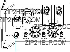
Teleskopantennen an der Ger??ter??ckseite anschlie??en
An das Quadpack m??ssen entweder die mitgelieferten Teleskopantennen oder abgesetzte Antennen angeschlossen werden. Diese bedienen die beiden Empfangszweige
ESchlie??en Sie die beiden Teleskopantennen an die
EZiehen Sie die Teleskopantennen ganz heraus und richten Sie sie
Hinweis:
Wenn der Empf??ngerstandort keinen optimalen Empfang bietet, k??nnen Sie abgesetzte Antennen verwenden. Aktive und passive abgesetzte An- tennen erhalten Sie als Zubeh??r (siehe ???Zubeh??r??? auf Seite 15). ??ber die Antennenbuchsen des Quadpacks k??nnen aktive Antennen gespeist wer- den.
Externes Netzteil anschlie??en (Zubeh??r)
Das externe Netzteil, das als Zubeh??r erh??ltlich ist, versorgt das Quadpack und die eingesteckten Empf??nger mit Strom.
EStecken Sie den
ESchlie??en Sie das Netzteil an das Stromnetz an.
Mischpult bzw. Verst??rker anschlie??en
Die Audiosignale der eingesteckten Empf??nger k??nnen Sie f??r jeden Empf??n- ger separat an 4
ESchlie??en Sie das Mischpult bzw. den Verst??rker an die
EPassen Sie die Ausgangspegel der
EMit den Stellern f??r den Ausgangspegel K k??nnen Sie die Ausgangs- pegel feineinstellen.
Hinweis:
Sie k??nnen die
8
Kopfh??rer anschlie??en
Zum Abh??ren der Audiosignale schlie??en Sie einen Kopfh??rer an den Kopf- h??reranschluss G an. Sie k??nnen die Audiosignale jeweils einzeln oder meh- rere gleichzeitig abh??ren.
E Drehen Sie den Lautst??rkesteller f??r den Kopfh??rerausgang F vorsich- tig nach rechts, bis die Lautst??rke ausreicht.
Laut h??ren? ??? NEIN!
Mit einem Kopfh??rer wird gern lauter geh??rt als mit Lautsprechern. Hohe Lautst??rke, die ??ber l??ngere Zeit auf Ihre Ohren einwirkt, kann zu dauerhaften H??rsch??den f??hren. Sch??tzen Sie Ihr Geh??r! Sennheiser- Kopfh??rer klingen auch bei niedriger Lautst??rke besonders gut.
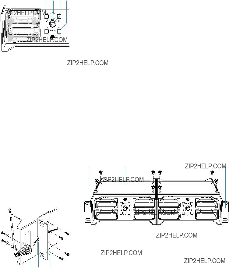
Rackmontage
Sie k??nnen zwei Quadpacks nebeneinander in ein
ELegen Sie die beiden Quadpacks nebeneinander mit der Unterseite nach oben auf einen Tisch.
ELegen Sie die Montageplatte A auf die Unterseiten der beiden Quad- packs und schrauben Sie sie mit den beiliegenden 8 Schrauben an den vorbereiteten Bohrungen fest.
B AB
E Schrauben Sie die beiden Montagewinkel B links und rechts an die bei-
C B
den verbundenen Quadpacks.
Wenn Sie beide Quadpacks mit einem auf der Frontseite montierten Antennenpaar betreiben wollen (siehe unten), fixieren Sie die beiden Kabel C vom Set f??r die
E Setzen Sie die Anlage in ein
9

Wenn Sie Ihre Quadpacks in ein Rack oder einen Turm einbauen, k??nnen Sie die Antennen alternativ auf der Frontseite montieren. Dazu ist als Zube- h??r das Set f??r die
E Schrauben Sie die Antennenhalter D an die beiden ??u??eren Griffe der beiden Quadpacks, wie nebenstehend gezeigt. Verwenden Sie dazu die vorbereiteten Bohrungen und die mitgelieferten 4 Schrauben und 4 Unterlegscheiben.
E F??hren Sie die beiden Kabel seitlich um die Quadpacks auf die R??ck- seite.
Wenn Sie die beiden Quadpacks in ein Rack einbauen wollen, fixieren Sie die beiden Kabel C vom Set f??r die
Zusammenschaltung von zwei Quadpacks
Wenn Sie zwei Quadpacks miteinander verbinden und nebeneinander in ein Rack einbauen, gen??gt ein einziges Antennenpaar. Sie k??nnen dieses Anten- nenpaar auch auf der Frontseite montieren, wie oben beschrieben.
ESchlie??en Sie je eine Antenne bzw. ein Kabel C des Sets f??r die Anten-
P O Q P O Q
* = zu den frontmontierten Antennen.
EVerbinden Sie die
10
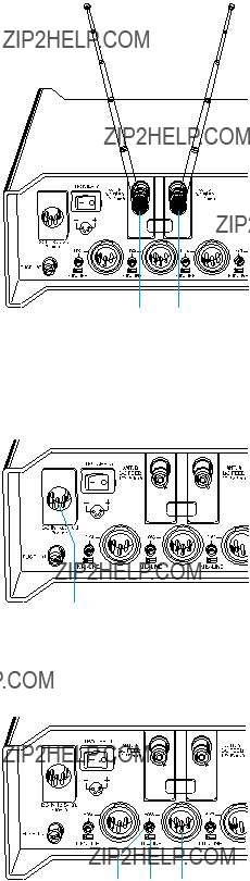
Eingangsmodule austauschen
Ihr Quadpack ist serienm????ig mit zwei breitbandigen Eingangsmodulen aus- gestattet, die f??r die meisten Empfangssituationen ausreichen. Wenn Sie mit dem Quadpack in Bereichen arbeiten, wo sehr viel
Die
Wichtiger Hinweis!
Beachten Sie beim Kauf der
Wenn Sie die
N
E Ziehen Sie die Antennenstecker bzw. die Teleskopantennen ab.
E Entriegeln Sie die Eingangsmodule, indem Sie die Verriegelung N in eine senkrechte Position drehen.
E Ziehen Sie die
E Setzen Sie die
E Verriegeln Sie die Eingangsmodule wieder.
E Schlie??en Sie die Antennen wieder an.
O
11
EEinzelne Empf??nger k??nnen nach Bedarf mit der Taste ???ON??? am Emp-
f??nger aus- und eingeschaltet werden.
Monitoring
Zum Abh??ren der eingesteckten Empf??nger m??ssen Sie einen Kopfh??rer an den Kopfh??reranschluss G anschlie??en.
E Sie k??nnen auch mehrere
Hinweis:
Der Monitorausgang besitzt eine hohe Verst??rkungsreserve, um auch bei geringer Modulationsaussteuerung tief in die ??bertragungsstrecke hin- einh??ren zu k??nnen. Stellen Sie daher die Lautst??rke des Monitoraus- gangs vorsichtig ein!
12
St??rungen beheben
Kein Empfang oder gest??rter Empfang
Die Betriebsanzeige leuchtet nicht ??? das Quadpack hat keinen Strom:
E??berpr??fen Sie, ob das Netzteil an das Stromnetz angeschlossen ist und der
EStecken Sie den Netzstecker in eine Steckdose, schlie??en Sie das Netzteil an das Quadpack an und schalten Sie den
Die Spannungsversorgung ist in Ordnung, aber trotzdem leuchtet die Be- triebsanzeige POWER nicht ??? die Sicherung des Quadpack hat ausgel??st und muss ersetzt werden:
EPr??fen Sie jeden nicht benutzten Schacht und entfernen Sie etwa hinein- gelangte Gegenst??nde.
EPr??fen Sie die
EStellen Sie den
E Schrauben Sie den Sicherungshalter I heraus.
E
E
E Schrauben Sie den Sicherungshalter I wieder ein.
E Stellen Sie den
Die Betriebsanzeige leuchtet rot.
I
Auf dem Display des Empf??ngers wird nichts angezeigt ??? der Empf??nger ist nicht eingeschaltet:
EDr??cken Sie die Taste ???ON??? am Empf??nger. Auf dem Display des Emp- f??ngers erscheint die gew??hlte Frequenz oder die
EStellen Sie alle mit dem Quadpack betriebenen
Das Frequenzfenster der
13
Antennen sind nicht richtig angeschlossen:
EPr??fen Sie alle Antennenanschl??sse. Wenn Sie zwei Quadpacks mitein- ander verbunden haben und an nur einem Antennenpaar betreiben, pr??- fen Sie bitte die Antennenverkabelung (siehe ???Zusammenschaltung von zwei Quadpacks??? auf Seite 10).
Die Sender sind ausgeschaltet oder die Sender befinden sich nicht im Emp- fangsbereich:
ESchalten Sie die Sender ein und stellen Sie sicher, dass zwischen Sender und Antenne ???Sichtverbindung??? besteht. Wenn Sie die Antennen nicht im optimalen Empfangsbereich aufstellen k??nnen, verwenden Sie abge- setzte Antennen (siehe ???Zubeh??r??? auf Seite 15).
Kein Monitorsignal im Kopfh??rer
Alle vier LEDs f??r Empf??nger leuchten rot ??? Sie haben keinen Empf??nger gew??hlt:
EDr??cken Sie einen oder mehrere
Der Lautst??rkesteller ist auf Linksanschlag eingestellt:
E Drehen Sie den Lautst??rkesteller vorsichtig nach rechts.
Zu leises, verrauschtes oder verzerrtes Audiosignal
Das Audiosignal klingt zu leise oder verzerrt ??? der Ausgangspegel des Quad- packs ist nicht an den Eingang des Mischpults bzw. Verst??rkers angepasst:
EPassen Sie die Ausgangspegel mit den
Beachten Sie auch die Hinweise in der Bedienungsanleitung Ihrer Emp- f??nger!
Das Monitorsignal klingt verzerrt ??? der
EReduzieren Sie die Lautst??rke des
Hinweis:
Der Monitorausgang besitzt eine hohe Verst??rkungsreserve, um auch bei geringer Modulationsaussteuerung tief in die ??bertragungsstrecke hin- einh??ren zu k??nnen.
14
Zubeh??r
F??r Ihr Quadpack erhalten Sie bei Sennheiser folgendes Zubeh??r:
15

Technische Daten
Gesamtger??t
16

17

INSTRUCTION MANUAL
Quadpack QP 3041
19
Thank you for choosing Sennheiser!
We have designed this product to give you reliable operation over many years. Over half a century of accumulated expertise in the design and manufacture of
Please take a few moments to read these instructions carefully, as we want you to enjoy your new Sennheiser product quickly and to the fullest.
20
Areas of application
The QP 3041 Quadpack is a mini rack for housing up to four EK 3041 receivers. Together with the suitable transmitters, the Quadpack makes a compact and mobile
The received audio signals are available at the AF outputs. Via the monitor output, the transmission links can be monitored either separately or simultaneously.
Two Quadpacks can be
The Quadpack has been specially designed for applications in the professional audio field, e.g. outdoor film applications.
Important notes
Never open electronic units! This must only be done by authorized personnel and is all the more important for units connected to AC outlets. If units are opened by customers in breach of this instruction, the warranty becomes null and void.
Keep the Quadpack away from central heating radiators and electric heaters. Never expose it to direct sunlight.
Use a damp cloth for cleaning the Quadpack. Do not use any cleansing agents or solvents.
Delivery includes
1 Quadpack
4 Telescopic antennas
4
1
4 Covers for receiver slots
1 Instruction manual
21
Operating elements
A B C D E F G
H I J K L M N O P Q
A Slot for EK 3041 receiver (4 x)
B Antenna connecting cable with
DControl LED for receiver (4 x) (red: in operation, green: audio signal also available at the headphone output)
E Operation indicator, red LED
F Headphone volume control
G Headphone output, 1/4" (6.3 mm) jack socket
H
I Fuse
J POWER (ON/OFF) switch
K AF output level control (4 x)
L Selector switch for output level (MIC/LINE, 4 x)
M
N Catch for input modules
O Input module with BNC socket for antenna input A
P Input module with BNC socket for antenna input B
Q BNC socket for antenna output
22

Putting the Quadpack into operation
D
Q R R Q
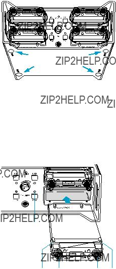
Mounting the plastic feet
To ensure that the Quadpack cannot slip on the surface on which it is placed, four
Note:
Do not use these feet if
EEnsure that the base of the Quadpack is clean and free from grease before mounting the plastic feet.
EFix the plastic feet to the base of the Quadpack by peeling off the safety paper and fitting them as shown in the diagram on the left.
Attention!
Some furniture surfaces have been treated with varnish, polish or synthetics which might cause stains when they come into contact with other synthetics. Despite a thorough testing of the synthetics used by us, we cannot rule out the possibility of discoloration, since we don???t know your furniture.
Mounting the EK 3041 receivers into the Quadpack
The EK 3041 receivers are inserted into the receiver slots and fixed by means of four screws.
EUnscrew the two antennas of the receiver.
EIf necessary, remove the
EInsert the receiver completely into the receiver slot as shown in the dia- gram on the left.
EFix the receiver to the receiver slot by fastening the screws to the four holes Q.
EScrew the
Note:
The mounted receivers are automatically turned on if the Quadpack is turned on. The control LEDs D next to the mounted receivers light up. Unused receivers can be turned off via their respective ON buttons.
23
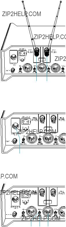
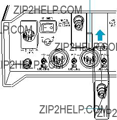
Connecting the telescopic antennas
The Quadpack can be used with either telescopic antennas (supplied) or remote antennas (available as accessories). The telescopic antennas can be mounted quickly and easily and are suitable for all applications where ??? good reception conditions provided ??? a wireless transmission system is to be used without a large amount of installation work.
E Connect the telescopic antennas to BNC sockets O and P.
E Pull the antennas out and align them upwards in a
Note:
If the receiver position is not the best antenna position for optimum reception, you can use remote antennas. Active and passive remote antennas are available as accessories (see ???Accessories??? on page 31). Active antennas can be supplied via the antenna sockets of the Quadpack.
PO
Connecting the external mains unit (accessory)
The external mains unit (available as an accessory) powers both the Quadpack and the mounted receivers.
E Insert the
E Connect the mains unit to the mains.
H
Connecting a mixing console or amplifier
The audio signals of the receivers are available ??? for each receiver separately ??? at the four
E Connect the mixing console or amplifier to the
E Use the
E Use the AF output level controls K to adjust the output levels.
K L M
Note:
The AF outputs of the Quadpack can also be connected to an AF input that has been designed for condenser microphones with phantom powering (P 48 ). The AF outputs of the Quadpack are protected against phantom powering.
24
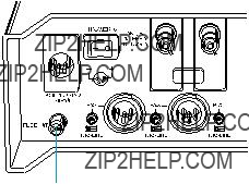
Connecting headphones
For monitoring the audio signals of the mounted receivers, connect a pair of headphones to the headphone output G. The audio signals can be monitored either separately or simultaneously.
C D F G E Turn the headphone volume control F
E Connect the headphones to the headphone output G.
E Press the monitor keys (RX 1 to RX 4) C next to the receivers that you
wish to monitor. The color of the control LEDs D below the pressed
monitor keys changes from red to green.
E Slowly turn the headphone volume control F clockwise until you have reached the desired volume.
Volume up? ??? NO!
When people use headphones, they tend to choose a higher volume than with loudspeakers. Listening at high volume levels for long periods can lead to permanent hearing defects. Please protect your hearing, Sennheiser headphones have an excellent sound quality even at low volumes.
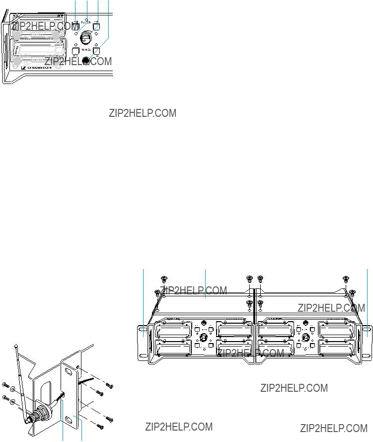
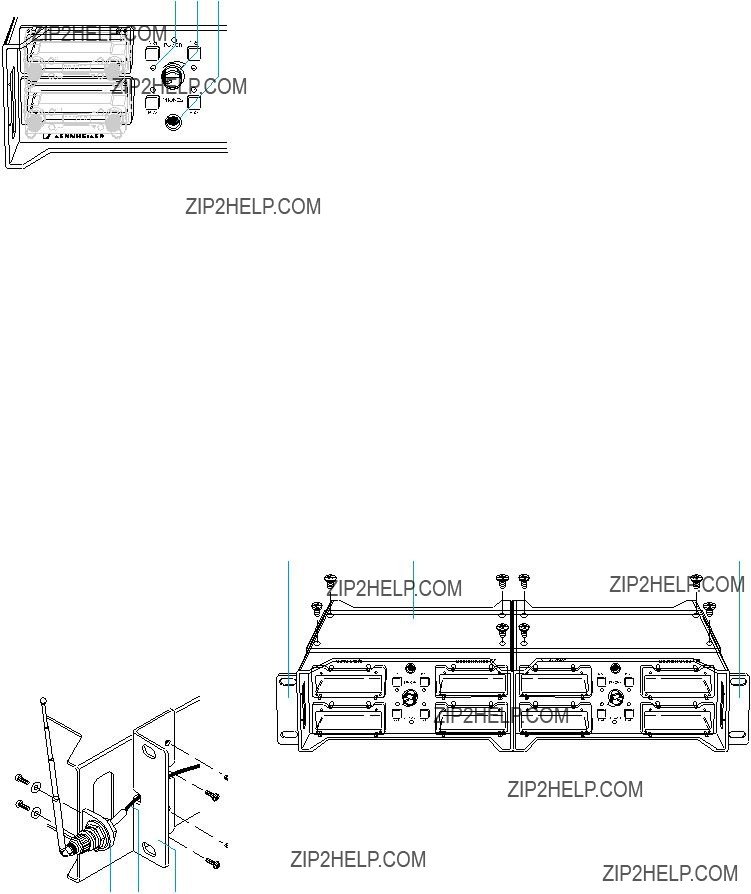
Mounting two Quadpacks into a rack
With the
EPlace the two Quadpacks side by side onto a table, their bottom sides facing upwards.
EPut the mounting plate A onto the bottom sides of the Quadpacks and fix it to the Quadpacks by means of the eight supplied screws.
B AB
25

Mounting the antennas to the front of the Quadpack
If your Quadpacks are to be mounted into a rack or a tower, the antennas can be connected to the front side by using the GA 3030 AM antenna mount (see ???Accessories??? on page 31).
E Mount the antenna holders D to the two outer handles of the two Quad- packs as shown in the diagram on the left. Fasten the antenna holders by means of the supplied four screws and plain washers to the prepared holes.
E Guide the two cables sideways to the rear of the Quadpacks.
If you wish to mount the two Quadpacks into a rack, fix the two cables C of the GA 3030 AM antenna mount to the rack mount ???ears??? B as shown in the diagram on the left.
E Connect the two telescopic antennas to the antenna holders D and align the antennas upwards.
D C B
If you
EConnect one antenna or one cable C of the GA 3030 AM antenna mount to the BNC socket ???ANT. A??? O of each Quadpack.
P O Q P O Q
* = to the antennas mounted to the front of the rack.
EConnect the BNC socket ???RF OUT A??? Q of each Quadpack to the BNC socket ???ANT. B??? P of the other Quadpack as shown in the diagram above.
26
Exchanging the input modules
Your Quadpack is fitted with two wideband input modules which are suitable for most applications. If the Quadpack is to be used mainly for high frequency transmission applications (e.g. electronic news gathering), we recommend using two selective input modules (see ???Accessories??? on page 31) to ensure optimum reception reliability.
The wideband input modules have a frequency range from 470 to 870 MHz. The selective input modules limit the bandwidth of the receiving frequencies to a
Important note!
When purchasing the selective input modules, make sure that their fre- quency window is compatible with the frequency range within which your transmitters and receivers can be operated!
When using the selective input modules, make sure that all transmitters and receivers of your transmission system operate within the frequency window of the selective input modules!
NE Remove the antenna cables or telescopic antennas.
E Unlock the input modules by turning the catch N into a vertical posi- tion.
E Pull the wideband input modules out.
E Insert the selective input modules O.
E Lock the input modules by turning the catch again.
E Reconnect the antennas.
O
27

J
E
C D G
Operation
Operating the receivers
The EK 3041 receivers mounted into the Quadpack are operated as ususal.
Turning the Quadpack on and off
ETo turn the Quadpack on, set the POWER (ON/OFF) switch J to posi- tion ???I???. The operation indicator E lights up red.
ETo turn the Quadpack off, set the POWER (ON/OFF) switch J to position ???0???. The operation indicator E goes off.
Note:
All receivers mounted into the Quadpack are turned on and off via the Quadpack???s POWER (ON/OFF) switch. If required, the individual receivers can be turned on and off via their respective ON buttons.
Monitoring
For monitoring the audio signals of the mounted receivers, connect a pair of headphones to the headphone output G.
EPress the monitor key C of the receiver whose audio signal you wish to monitor. The color of the control LED D of the selected receiver chan- ges from red to green.
EYou can also press several monitor keys if you wish to monitor the audio signals of several receivers simultaneously. The control LEDs of all selected receivers light up green.
Note:
The monitor output has enough amplification headroom in order to enable monitoring even at low modulation levels. The volume at the monitor output should therefore only be turned up gradually!
28
Trouble shooting
No reception or disturbed reception
The operation indicator doesn???t light up ??? the Quadpack is not powered:
ECheck if the mains unit is connected to the mains and if the POWER (ON/OFF) switch is set to position ???I???.
EPlug the mains connector to a wall socket, connect the mains unit to the Quadpack and set the POWER (ON/OFF) switch to position ???I???. The operation indicator lights up red.
The Quadpack???s power supply has already been checked, but the operation indicator still doesn???t light up ??? the fuse of the Quadpack has been triggered:
ECheck every unused receiver slot for objects that might have triggered the fuse and remove these objects.
ECheck the DC polarity of the power supply. The correct polarity is shown in the diagram next to the socket!
ESet the POWER (ON/OFF) switch to position ???0???.
E Unscrew and remove the fuse holder I.
E
E
E Replace the fuse holder I and screw it tight.
E Set the POWER (ON/OFF) switch to position ???I???.
The operation indicator E lights up red.
I
The receiver display remains dark ??? the receiver has not been turned on:
EPress the ON button on the receiver. The receiver display indicates the selected frequency or the channel number.
Selective input modules are used but the selected transmission and receiving frequencies are not within the frequency window of the selective input modules:
ESet all transmitters and receivers operated with the Quadpack to frequencies that are within the frequency window of the selective input module.
The frequency window of the selective input modules is printed onto the modules.
The antennas are not connected correctly:
ECheck all antenna connections. If two
29
The transmitters are turned off or the transmitters are not within the reception area:
ETurn the transmitters on and make sure that there is a ???free line of sight??? between the transmitters and the receiving antennas. If the receiver position is not the best antenna position for optimum reception, use remote antennas (see ???Accessories??? on page 31).
No monitoring signal available
All control LEDs for the receivers light up red ??? no receiver has been selected:
EPress one or several monitor keys. The control LEDs of the selected receivers light up green.
The headphone volume control is turned fully
E Slowly turn the headphone volume control clockwise.
Audio signal is too low or slightly noisy or distorted
The audio signal is too low or distorted ??? the output level of the Quadpack has not been adapted to the input of the mixing console or amplifier:
EUse the
Please also observe the notes given in the receiver???s instruction manual!
The monitoring signal is distorted ??? the volume at the monitor output is adjusted too high so that the headphone amplifier is overmodulated:
EUse the headphone volume control to reduce the volume at the monitor output.
Note:
The monitor output has enough amplification headroom in order to enable monitoring even at low modulation levels.
30
Accessories
The following accessories are available from Sennheiser:
31
Specifications
Overall unit
32

RF characteristics
33
34

NOTICE D???EMPLOI
Quadpack QP 3041
35
Merci d???avoir choisi Sennheiser!
Nous avons con??u ce produit pour une fiabilit?? maximale pendant de nombreuses ann??es. Plus d???un
Prenez le temps de lire ces instructions avec soin : elles vous permettront d???exploiter rapidement votre nouvel appareil Sennheiser, ?? son maximum.
36
Domaines d???application
Le Quadpack QP 3041 est un
Le Quadpack fournit la tension d???alimentation et les branchements d???antenne ?? tous les r??cepteurs mont??s.
Les signaux audio re??us sont disponibles sur les sorties audio (AF). La sortie Monitor permet de v??rifier la qualit?? de la liaison de transmission, soit s??par??ment, soit simultan??ment. Il est possible de ???cascader??? deux Quadpacks : ils fonctionnent alors avec une seule paire d???antennes.
Le Quadpack a ??t?? sp??cialement con??u pour des applications dans le domaine audio professionnel ??? par exemple, des tournages film en ext??rieur.
Pr??cautions importantes
N???ouvrez jamais un appareil ??lectronique, surtout s???il est reli?? au secteur ! Toute inspection ou r??paration doit ??tre effectu??e par des techniciens autoris??s. Toute ouverture par le client d???un appareil annule la garantie.
Eloignez le Quadpack de toute source de chaleur : radiateur de chauffage central ou radiateur ??lectrique, par exemple. Ne jamais exposer directement l???appareil aux rayons du soleil.
Pour nettoyer le Quadpack, utilisez un chiffon humide. N???employez jamais de d??tergents ou de solvants.
Contenu de la livraison
1 Quadpack
4 antennes t??lescopiques
4 pieds plastiques autocollants
1 connecteur
4 cachse pour les slots r??cepteur
1 Notice d???emploi
37

Les diff??rentes parties du Quadpack
A B C D E F G
H I J K L M N O P Q
A Slot pour r??cepteur EK 3041 (4 x)
B C??ble de branchement antenne, avec connecteur coud?? (8 x) C Touche Monitor (4 x)
DLED de contr??le pour r??cepteur (4 x) (rouge: en fonctionnement, vert: signal audio ??galement disponible sur la sortie casque)
E Indicateur de fonctionnement, LED rouge F R??glage de volume du casque
G Sortie casque, sur embase jack 6,35 mm
H Embase
J Interrupteur POWER (ON/OFF)
K Potentiom??tre de r??glage du niveau de sortie (4 x) L S??lecteur de niveau de sortie (MIC/LINE, 4 x)
M Embase
O Module d???entr??e avec embase BNC pour entr??e antenne A P Module d???entr??e avec embase BNC pour entr??e antenne B Q Embase BNC pour sortie antenne
38

Pr??paratifs pour la mise en fonction
Montage des pieds plastique
Pour s???assurer que le Quadpack ne peut pas glisser sur la surface sur laquelle il est plac??, quatre pieds plastiques autocollants sont fournis.
Note :
Ne pas utiliser ces pieds si vous montez le Quadpack dans un rack !
E V??rifiez que la base du Quadpack est propre, sans d??p??t gras, avant de mettre en place les pieds plastiques.
E Fixez les pieds en plastique ?? la base du Quadpack, en ??tant le papier de s??curit?? puis en les mettant en place comme indiqu?? sur le sch??ma ci- contre.
Attention !
Certaines surfaces de meubles, trait??es avec un vernis, du polish ou autres produits synth??tiques peuvent ??tre tach??es au contact d???autres mati??res synth??tiques. En d??pit des tests minutieux men??s sur les mati??res plastiques que nous utilisons, comme nous ne connaissons pas la composition de vos meubles, nous ne pouvons ??carter toute possibilit?? de d??coloration.
Mise en place des r??cepteurs EK 3041 dans le Quadpack
Les r??cepteurs EK 3041 s???ins??rent dans les slots pr??vus ?? cet effet, et fix??s par l???interm??diaire de quatre vis.
Quadpack est mis sous tension. Les LED de contr??le D, situ??es pr??s des r??cepteurs en place, s???allument alors. Les r??cepteurs inutilis??s peuvent ??tre d??sactiv??s via leurs touches ON respectives.
39

P O
H
K L M
Branchement des antennes t??lescopiques
Le Quadpack peut ??tre utilis?? soit avec des antennes t??lescopiques (fournies) ou des antennes d??port??es (disponibles en accessoire). Les antennes t??lescopiques se montent rapidement et facilement, et conviennent ?? toutes les applications pour lesquelles on doit pouvoir utiliser un syst??me d?????mission HF sans devoir passer beaucoup de temps en installation ??? en supposant de bonnes conditions de r??ception.
EReliez les antennes t??lescopiques aux embases BNC O et P.
ED??ployez les antennes et
Note :
Si l???emplacement du r??cepteur ne correspond pas ?? une position optimale des antennes, vous pouvez utiliser des antennes d??port??es. De telles an- tennes, actives ou passives, sont disponibles en accessoire (voir ???Acces- soires??? ; page 47). Les antennes actives peuvent ??tre aliment??es via les embases d???antenne du Quadpack.
Branchement du bloc secteur externe (accessoire)
Le bloc secteur externe (disponible en accessoire) permet d???alimenter ?? la fois le Quadpack et les r??cepteurs qui y sont install??s.
EIns??rez le connecteur
EBranchez le bloc secteur sur une prise.
Branchement ?? une console de mixage ou ?? un amplificateur
Les signaux audio des r??cepteurs sont disponibles ??? s??par??ment pour chaque r??cepteur ??? sur les quatre embases
EReliez la console de mixage ou l???amplificateur aux embases
EPour adapter les niveaux de sortie aux entr??es de la console ou de l???amplificateur, utilisez les s??lecteurs
EPour r??gler les niveaux de sortie audio, utilisez les potentiom??tres de niveau de sortie K.
Note :
Les sorties audio du Quadpack peuvent aussi ??tre reli??es ?? une entr??e audio con??ue pour alimenter des microphones ??lectrostatiques (pourvue d???une alimentation fant??me 48 Volts). Les sorties audio du Quadpack sont prot??g??es contre la pr??sence d???une alimentation fant??me.
40
Le volume ?? fond ? ??? NON !!
Lorsqu???on travaille au casque, on a souvent tendance ?? ??couter plus fort qu???on ne le ferait avec des enceintes. Attention : les niveaux d?????coute ??lev??s, lorsqu???ils sont maintenus pendant de longues p??riodes, peuvent occasionner des l??sions auditives permanentes. Prot??gez votre audition : les casques Sennheiser offrent une excellente qualit?? d?????coute m??me ?? bas niveau.
Montage en rack de deux Quadpacks
Le kit de montage en rack (voir ???Accessoires??? ; page 47) permet de monter c??te ?? c??te deux Quadpacks dans un rack 19 pouces.
EDisposez les deux Quadpacks c??te ?? c??te retourn??s sur une table.
EMettez en place la plaque de montage A sur le fond des Quadpacks, puis
B AB
41
Montage des antennes ?? l???avant du Quadpack
Si vos Quadpacks doivent ??tre mont??s dans un rack ou une tour, les antennes peuvent ??tre plac??es en face avant, les antennes peuvent ??tre report??es en face avant, en utilisant un kit de d??port d???antenne GA 3030 AM (voir ???Accessoires??? ; page 47).
E Montez les supports d???antenne D sur les deux poign??es ext??rieures des deux Quadpacks, comme indiqu?? dans le sch??ma
E Guidez les deux c??bles sur le c??t??, jusqu????? l???arri??re des Quadpacks.
Si vous d??sirez monter les deux Quadpacks dans un rack, fixez les deux c??bles C du kit de d??port d???antenne GA 3030 AM aux oreilles de mon- tage en rack B, comme indiqu?? sur le sch??ma
E Reliez les deux antennes t??lescopiques aux supports d???antenne D puis d??ployez les antennes vers le haut.
D C B
Branchement de deux Quadpacks en cascade
Si vous d??cidez de monter en cascade deux Quadpacks, c??te ?? c??te dans un rack, ils peuvent utiliser la m??me paire d???antennes.
EConnectez une antenne ou un c??ble C du kit de d??port d???antenne GA 3030 AM ?? l???embase BNC rep??r??e ???ANT. A??? O de chaque Quadpack.
P O Q P O Q
* = vers les antennes mont??es ?? l???avant du rack
.
EReliez l???embase BNC rep??r??e ???RF OUT A??? Q de chacun des Quadpacks ?? l???embase BNC ???ANT. B??? P de l???autre Quadpack, comme indiqu?? dans le sch??ma
42

Echange des modules d???entr??e
Votre Quadpack est fourni avec deux modules d???entr??e large bande, qui conviennent ?? la plupart des applications. Si le Quadpack est utilis?? dans des applications en longue port??e en ext??rieur (par exemple, en reportage sur le terrain), nous recommandons d???utiliser des modules d???entr??e s??lectifs (voir ???Accessoires??? ; page 47) afin d???assurer une fiabilit?? optimale en r??ception.
Les modules d???entr??e ???large bande??? poss??dent une gamme de fr??quences allant de 470 ?? 870 MHz. Les modules d???entr??e s??lectifs limitent la largeur de bande des fr??quences de r??ception ?? une fen??tre de 40 MHz ?? l???int??rieur de cette gamme. La fen??tre de fr??quence des modules d???entr??e s??lectifs est imprim??e sur les modules
Note importante !
Si vous achetez des modules d???entr??e s??lectifs,
Lorsque vous utilisez les modules d???entr??e s??lectifs, v??rifiez que tous les ??metteurs et r??cepteurs de votre syst??me de transmission travaillent dans la fen??tre de fr??quences des modules d???entr??e s??lectifs.
N
E D??montez les c??bles d???antenne ou les antennes t??lescopiques.
E D??verrouillez les modules d???entr??e en faisant pivoter la barrette N en position verticale.
E Retirez les modules d???entr??e large bande.
E Ins??rez ?? la place les modules d???entr??e s??lectifs O.
E Verrouillez les modules d???entr??e en faisant pivoter ?? nouveau la barrette.
E Rebranchez les antennes.
O
43

Etension via l???interrupteur POWER (ON/OFF) du Quadpack. Si n??cessaire,
les r??cepteurs peuvent ??tre allum??s ou ??teints s??par??ment, via leurs touches ON respectives.
Ecoute de contr??le
Pour ??couter les signaux audio des r??cepteurs mont??s, reliez un casque ?? la prise casque ?? la sortie casque G.
E Rien ne vous emp??che d???appuyer sur plusieurs touches Monitor si vous d??sirez ??couter simultan??ment les signaux audio provenant de plusieurs r??cepteurs. Les LED de contr??le de tous les r??cepteurs s??lectionn??s s???allument alors en vert.
Note :
L???amplificateur ??quipant la sortie Monitor poss??de une gamme dynamique suffisamment ??tendue pour permettre l?????coute de signaux de niveau faible. Attention ?? ne pas monter trop ??nergiquement le niveau sur la sortie casque !
44

En cas de probl??me...
Pas de r??ception, ou r??ception perturb??e
Le t??moin de fonctionnement ne s???allume pas ??? le Quadpack n???est pas aliment?? :
EV??rifiez si le bloc secteur est bien branch?? ?? une prise, et que l???interrup- teur POWER (ON/OFF) se trouve en position ???I???.
EBranchez le bloc secteur dans une prise murale, puis
L???alimentation du Quadpack a d??j?? ??t?? v??rifi??e, mais l???indicateur ne s???allume toujours pas ??? le fusible du Quadpack a fondu :
EV??rifiez la pr??sence ??ventuelle d???un objet pouvant faire
EV??rifiez la polarit?? de l???alimentation. La polarit?? correcte est indiqu??e dans le diagramme se trouvant pr??s de l???embase.
EPlacez l???interrupteur POWER (ON/OFF) en position ???0???.
E D??vissez le
E
E
E Remettez en place le
E Placez l???interrupteur POWER (ON/OFF) en position ???I???.
L???indicateur de fonctionnement E doit s???allumer en rouge.
I
L???affichage du r??cepteur reste ??teint ??? le r??cepteur n???est pas sous tension :
EAppuyez sur la touche ON du r??cepteur. Son affichage indique alors la fr??quence s??lectionn??e ou le num??ro de canal.
Des modules d???entr??e s??lectifs sont utilis??s, mais les fr??quences d?????mission et de r??ception s??lectionn??es ne se trouvent pas dans la fen??tre de fr??quences des modules d???entr??e s??lectifs :
ER??glez tous les ??metteurs et r??cepteurs se trouvant dans le Quadpack sur des fr??quences se trouvant dans la fen??tre de fr??quences du module d???entr??e s??lectif.
Les valeurs concernant la fen??tre de fr??quences du module d???entr??e s??lectif sont imprim??es sur les modules
45
Les antennes ne sont pas correctement branch??es :
EV??rifiez tous les branchements d???antennes. Si deux Quadpacks sont configur??s en cascade et se partagent une m??me paire d???antennes, v??rifiez les c??blages d???antennes (voir ???Branchement de deux Quadpacks en cascade
Les ??metteurs sont ??teints ou ne se trouvent pas dans la zone de r??ception :
EMettez les ??metteurs sous tension, et v??rifiez qu???une ???ligne de communication visuelle??? est m??nag??e entre les ??metteurs et les antennes de r??ception. Si l???emplacement o?? se trouve le r??cepteur n???est pas optimal au niveau de l???antenne, utilisez des antennes d??port??es (voir ???Accessoires??? ; page 47).
Aucun signal disponible en ??coute de contr??le
Toutes les LED de contr??le des r??cepteurs sont rouges ??? aucun r??cepteur n???a ??t?? s??lectionn?? :
EAppuyez sur une ou plusieurs touches Monitor. Les LED de contr??le des r??cepteurs s??lectionn??s s???allument en vert.
Le r??glage de niveau d?????coute casque est tourn?? ?? fond ?? gauche :
ETournez progressivement le potentiom??tre de niveau casque dans le sens des aiguilles d???une montre.
Signal audio trop faible, l??g??rement bruyant ou affect?? de distorsion
Le signal audio est trop faible ou affect?? de distorsion ??? c???est que le niveau de sortie du Quadpack n???est pas adapt?? ?? l???entr??e de la console de mixage ou de l???amplificateur :
EAvec le s??lecteur
Le signal de contr??le audio est distordu ??? le niveau de la sortie Monitor est trop ??lev??, ce qui surcharge l???amplificateur casque :
EAvec le potentiom??tre de r??glage de niveau de casque, r??duisez le volume de la sortie Monitor.
Note :
L???amplificateur ??quipant la sortie Monitor poss??de une gamme dynamique suffisamment ??tendue pour permettre l?????coute de signaux de niveau faible.
46
Accessoires
Les accessoires suivants sont disponibles aupr??s de votre revendeur Sennheiser :
47

Caract??ristiques
G??n??ralit??s
48

Caract??ristiques HF
49
50

Konformit??tserkl??rung
Sennheiser electronic GmbH & Co. KG erkl??ren, dass dieses Ger??t die an- wendbaren
Approval
Sennheiser electronic GmbH & Co. KG declare that this device is in com- pliance with the applicable CE standards and regulations.
Certification
Sennheiser electronic GmbH & Co. d??clarons que cet appareil est en confor- mit?? avec les normes CE.