www.seuservice.com
2nd PRINTING AUG
Deluxe Version
OWNER???S MANUAL
SEGA ENTERPRISES, INC. USA
MANUAL NO.
www.seuservice.com
2nd PRINTING AUG
Deluxe Version
OWNER???S MANUAL
SEGA ENTERPRISES, INC. USA
MANUAL NO.

VISIT OUR WEBSITE!

BEFORE USING THE PRODUCT, BE SURE TO READ THE FOLLOWING:
To maintain the safety:
To ensure the safe usage of the product, be sure to read the following before using the product. The following instructions are intended for the users, operators and the personnel in charge of the operation of the product. After carefully reading and sufficiently understanding the warning displays and cautions, handle the product appropriately. Be sure to keep this manual nearby the product or elsewhere convenient for referring to it when necessary.
Herein, explanations which require special attention are enclosed with dual lines. Depending on the poten- tially hazardous degrees, the terms of WARNING, CAUTION, etc. are used. Be sure to understand the contents of the displays before reading the text.
Indicates that mishandling the product by disregarding this warning will cause a potentially hazardous situation which can result in death or serious injury.
Indicates that mishandling the product by disregarding this caution will cause a slight hazardous situation which can result in personal injury and or material damage.
For the sage usage of the product, the following pictographs are used:
Indicates ???HANDLE WITH CARE.??? In order to protect the human body an equipment, this display is attached to places where the Owner???s Manual and or Service Manual should be referred to.
 Perform work in accordance with the instructions herein stated.
Instructions for work are explained by paying attention to the aspect of accident prevention. Failing to perform work as per the instructions can cause accidents. In the case where only those who have techni- cal expertise should perform the work to avoid hazardous situation, the instructions herein state that the serviceman should perform such work.
Be sure to turn off power before working on the machine.
To prevent electric shock, be sure to turn off power before starting the work in which the worker touches the interior of the product. If the work is to be performed in the
Be sure to ground the Earth Terminal (this, however, is not required in the case where a power cord with earth is used).
This product is equipped with the Earth Terminal. When installing the product, Connect the Earth Termi- nal to the ???accurately grounded indoor earth terminal??? by using an earth wire. Unless the product is grounded appropriately, the user can be subject to electric shock. After performing repair, etc. for the Control equipment, ensure that the Earth Wire is firmly connected to the Control equipment.
Ensure that the Power Supply used is equipped with an Earth Leakage Breaker.
This product does not incorporate the Earth Leakage Breaker. Using a power supply which is not equipped with the Earth Leakage Breaker can cause a fire when earth leakage occurs.
Be sure to use fuses which meet the specified rating. (only for the machines which use fuses). Using fuses exceeding the specified rating can cause a fire and electric shock.

Specification changes (removal of equipment, conversion and addition) not designated by SEGA are not allowed.
The parts of the product include warning labels for safety, covers for personal protection, etc. It is very hazardous to operate the product by removing parts and or modifying the circuits. Should doors, lids and protective parts be damaged or lost, refrain from operating the product, and contact where the product was purchased from or the office herein stated. SEGA shall not be held responsible for any accidents, compensation for damage to a third party, resulting from the specifications not designated by SEGA.
Ensure that the product meets the requirements of appropriate Electrical Specifications.
Before installing the product, check for Electrical Specifications. SEGA products have a nameplate on which Electrical Specifications are described. Ensure that the product is compatible with the power supply voltage and frequency requirements of the location. Using any Electrical Specifications different from the designated Specifications can cause a fire and electric shock.
Install and operate the product in places where appropriate lighting is available, allowing warning labels to be clearly read.
To ensure safety for the customers, labels and printed instructions describing potentially hazardous situation are applied to places where accidents can be caused. Ensure that where the product is operated has sufficient lighting allowing the warnings to be read. If any label is peeled off, apply it again imme- diately. Please place an order with where the product was purchased from or the office herein stated.
When handling the Monitor, be very careful. (Applies only to the product w/monitor.)
Some of the monitor (TV) parts are subject to high tension voltage. Even after running off power, some portions are still subject to high tension voltage sometimes. Monitor repair and replacement should be performed only be those technical personnel who have knowledge of electricity and technical expertise.
Be sure to adjust the monitor (projector) properly. (Applies only to the product w/monitor.)
Do not operate the product leaving
When transporting or reselling this product, be sure to attach this manual to the product.
In the case where commercially available monitors and printers are used in this product, only the contents relating to this product are explained herein. Some commercially available equipment has functions and reactions not stated in this manual. Read this manual together with the specific Instruc- tion Manual of such equipment.
???Descriptions herein contained may be subject to improvement changes without notice.
???The contents described herein are fully prepared with due care. However, should any question arise or errors be found, please contact SEGA.
INSPECTIONS IMMEDIATELY AFTER TRANSPORTING THE PRODUCT TO THE LOCATION.
Normally, at the time of shipment, SEGA products are in a status allowing for usage immediately after transporting to the location. Nevertheless, an irregular situation may occur during transportation. Before turning on power, check the following points to ensure that the product has been transported in a satisfac- tory status.
Are there any dented portions or defects (cuts, etc.) on the external surfaces of the cabinet?
Are Casters and Adjusters, damaged?
Do the power supply voltage and frequency requirements meet with those of the location?
Are all wiring connectors correctly and securely connected? Unless connected in the correct direction, connector connections can not be made accurately. Do not insert connectors forcibly.

 Do power cords have cuts and dents?

 Do the fuses used meet specified rating? Is the Circuit Protector in an energized status? Are all accessories available?

 Can all Doors and Lids be opened with the Accessory keys? Can Doors and Lids be firmly closed?

TABLE OF CONTENTS

INTRODUCTION OF THE OWNERS MANUAL
This Owner's Manual is intended to provide detailed descriptions together with all the necessary information covering the general operation of electronic assemblies, electromechanicals, servicing control, spare parts, etc. as regards the product,
F355 CHALLENGE DX TYPE.
This manual is intended for the owners, personnel and managers in charge of operation of the product. Operate the product after carefully reading and sufficiently understanding the instructions. If the product fails to function satisfactorily, non- technical personnel should under no circumstances touch the internal system. Please contact where the product was purchased from.
Use of this product is unlikely to cause physical injuries or damages to property. However, where special attention is required this is indicated by a thick line, the word "IMPORTANT" and its sign in this manual.
IMPORTANT
SEGA ENTERPRISES, INC. (U.S.A.)/CUSTOMER SERVICE
45133 Industrial Drive, Fremont, California 94538, U.S.A.
Phone : (415)
Fax : (415)

DEFINITION OF LOCATION MAINTENANCE MAN AND SERVICEMAN
Ensure that parts replacement, servicing & inspections, and troubleshooting are performed by the location's maintenance man or the serviceman. It is instructed herein that particularly hazardous work should be performed by the serviceman who has technical expertise and knowledge.
The location's maintenance man and serviceman are herein defined as follows:
"Location's Maintenance Man" :
Those who have experience in the maintenance of amusement equipment and vending machines, etc., and also participate in the servicing and control of the equipment through such routine work as equipment assembly and installation, servicing and inspections, replacement of units and consumables, etc. within the Amusement Facilities and or locations under the management of the Owner and Owner's Operators of the product.
Activities of Location's Maintenance Man :
Assembly & installation, servicing & inspections, and replacement of units & consumables as regards amusement equipment, vending machines, etc.
Serviceman :
Those who participate in the designing, manufacturing, inspections and maintenance service of the equipment at an amusement equipment manufacturer.
Those who have technical expertise equivalent to that of technical high school graduates as re- gards electricity, electronics and or mechanical engineering, and daily take part in the servicing & control and repair of amusement equipment.
Serviceman's Activities :
Assembly & installation and repair & adjustments of electrical, electronic and mechanical parts of amusement equipment and vending machines.
LISTED
U?? L 5K92
AMUSEMENT MACHINE

1. HANDLING PRECAUTIONS
When installing or inspecting the machine, be very careful of the following points and pay attention to ensure that the player can enjoy the game safely.
STOP
IMPORTANT!
???Before performing work, be sure to turn power off. Performing the work without turning power off can cause an electric shock or short circuit. In the case work should be performed in the status of power on, this manual always states to that effect.
???To avoid electric shock or short circuit, do not plug in or unplug quickly.
???To avoid electric shock, do not plug in or unplug with a wet hand.
???Do not expose Power Cords and Earth Wires on the surface, (floor, passage, etc.). If exposed, the Power Cords and Earth Wires are susceptible to damage. Damaged cords and wires can cause electric shock or short circuit.
???To avoid causing a fire or electric shock, do not put things on or damage Power Cords.
???When or after installing the product, do not unnecessarily pull the power cord. If damaged, the power cord can cause a fire or electric shock.
???In case the power cord is damaged, ask for replacement through where the product was purchased from or the office herein stated. Using the cord as is damaged can cause fire, electric shock or leakage.
???Be sure to perform grounding appropriately. Inappropriate grounding can cause an electric shock.
???Be sure to use fuses meeting specified rating. Using fuses exceeding the specified rating can cause a fire or electric shock.
???Completely make connector connections for IC BD and others. Insufficient insertion can cause an electric shock.
???To avoid causing a fire or electric shock, do not make Specification changes by removing, converting and making additions unless otherwise designated by SEGA.
???Be sure to perform periodic maintenance inspections herein stated.
???For the IC board circuit inspections, only the logic tester is allowed. The use
of a
???When cleaning the CRT surfaces, use a soft, dry cloth. Do not apply chemicals such as thinner, benzine, etc.
???The electronic parts on the IC Board could be damaged due to human body's static electricity. Before performing IC Board related work, be sure to discharge physically accumulated statics by touching grounded metallic surfaces, etc.

2. PRECAUTIONS CONCERNING INSTALLATION
LOCATION
This product is an indoor game machine. Do not install it outside. Even indoors, avoid installing in places mentioned below so as not to cause a fire, electric shock, injury and or malfunctioning.
???Places subject to rain or water leakage, or places subject to high humidity in the proximity of an indoor swimming pool and or shower, etc.
???Places subject to direct sunlight, or places subject to high temperatures in the proximity of heating units, etc.
???Places filled with inflammable gas or vicinity of highly inflammable/volatile chemicals or hazardous matter.
???Dusty places.
???Sloped surfaces.
???Places subject to any type of violent impact.
???Vicinity of
???The operating (ambient) temperature range is from 5??C to 40??C.
Only in the case a projector is employed, the temperature range is from 5??C to 30??C.
LIMITATIONS OF USAGE REQUIREMENTS
???Be sure to check the Electrical Specifications.
Ensure that this product is compatible with the location's power supply, voltage and frequency requirements.
A plate describing Electrical Specifications is attached to the product.
???This product requires the Breaker and Earth Mechanisms as part of the location facilities. Using them in a manner not independent can cause a fire and electric shock.
???Ensure that the indoor wiring for the power supply is rated at 15A or higher (AC single phase 100 ~ 120V area), and 7A or higher (AC 220 ~ 240V area).
???Be sure to independently use the power supply equipped with the Earth Leakage Breaker. Using a power supply without the Earth Leakage Breaker can cause an outbreak of fire when earth leakage occurs.
???Putting many loads on one electrical outlet can cause generation of heat and a fire resulting from overload.
???When using an extension cord, ensure that the cord is rated at 15A or higher (AC 100 ~ 120V area) and 7A or higher (AC 220 ~ 240V area). Using a cord rated lower than the specified rating can cause a fire and electric shock.

STOP
IMPORTANT!
Electric current consumption
MAX. 8.70 A (AC 110V 50 Hz)
MAX. 8.30 A (AC 110V 60 Hz)
MAX. 7.70 A (AC 120V 60 Hz)
MAX. 4.50 A (AC 220V 50 Hz)
MAX. 4.30 A (AC 220V 60 Hz)
MAX. 4.20 A (AC 230V 50 Hz)
MAX. 4.00 A (AC 230V 60 Hz)
MAX. 4.10 A (AC 240V 50 Hz)
MAX. 3.90 A (AC 240V 60 Hz)
MAX. 8.30 A (For TAIWAN)
???For transporting the machine into the location's building, the minimum necessary dimensions of the opening (of doors, etc.) are 1.2m(W) and 1.7m(H).
???For the operation of this machine, secure a minimum area of 2.49m (W) X 3.16m (D). For ventilation, provide an approximately 20cm. space between the rear part of the cabinet and the wall.
FIG. 2
3. OPERATION
PRECAUTIONS TO BE HEEDED BEFORE STARTING THE OPERATION
To avoid injury and trouble, be sure to constantly give careful attention to the behavior and manner of the visitors and players.
In order to avoid accidents, check the following before starting the operation:
???Check if all of the adjusters are in contact with the surface. If they are not, the Cabinet can move and cause an accident.
234567890123456789012345678901212345678901234567890123456789012123456789012345678901234567890121 2
234567890123456789012345678901212345678901234567890123456789012123456789012345678901234567890121 2
234567890123456789012345678901212345678901234567890123456789012123456789012345678901234567890121 2
234567890123456789012345678901212345678901234567890123456789012123456789012345678901234567890121 2
234567890123456789012345678901212345678901234567890123456789012123456789012345678901234567890121 2
2345678901234567890123456789012123456789012345678901234567890121234567890123456789012345678901212
Ensure that all of the Adjusters are in contact with the floor.
???Do not put any heavy item on this product. Placing any heavy item on the product can cause a falling down accident or parts damage.
???Do not climb on the product. Climbing on the product can cause falling down accidents. To check the top portion of the product, use a step.
???To avoid electric shock, check to see if door & cover parts are damaged or omitted.
???To avoid electric shock, short circuit and or parts damage, do not put the following items on or in the periphery of the product.
Flower vases, flowerpots, cups, water tanks, cosmetics, and receptacles/ containers/vessels containing chemicals and water.
To avoid injury, be sure to provide sufficient space by considering the potentially crowded situation at the installation location. Insufficient installation space can cause the customers to come into contact with or hit the others and result in injury or trouble.

PRECAUTIONS TO BE HEEDED DURING OPERATION (PAYING ATTENTION TO CUSTOMERS)
To avoid injury and trouble, be sure to constantly give careful attention to the behavior and manner of the visitors and players.
???To avoid injury and accidents, those who fall under the following categories are not allowed to play the game.
???Those who need assistance such as the use of an apparatus when walking.
???Those who have high blood pressure or a heart problem.
???Those who have experienced muscle convulsion or loss of consciousness when playing video game, etc.
???Those who have a trouble in the neck and or spinal cord.
???Intoxicated persons.
???Pregnant women or those who are in the likelihood of pregnancy.
???Persons susceptible to motion sickness.
???Persons whose act runs counter to the product's warning displays.
???To avoid injury resulting from falling down, and electric shock due to spilled drinks, instruct the player not to place heavy items or drinks on the product.
???To avoid electric shock and short circuit, do not allow customers to put hands and fingers or extraneous matter in the openings of the product or small openings in or around the doors.
???To avoid falling down and injury resulting from falling down, immediately stop the customer's leaning against or climbing on the product, etc.
???To avoid electric shock and short circuit, do not allow the customers to unplug the power plug without a justifiable reason.
???To avoid a fire due to a cigarette stub, caution the customers so as not to put dust on the Seat rear.
???Caution the customers so as not to put dust on the outlet for driving records. Failure to observe this may cause a fire due to cigarette stubs.
???This product is intended for 1 Player only. Playing the game by 2 or more Players riding on the seat together can cause falling down and collision accidents by striking head, hand, or elbow.
???Immediately stop such violent acts as hitting and kicking the product. Such violent acts can cause parts damage or falling down, resulting in injury due to fragments and falling down.
???To avoid collision or falling down accident, caution the customers so as not to come in to the Seat rear.
???Instruct the Player to take firm hold of the Steering Wheel when in play. The Steering Wheel is equipped with reaction mechanism. Holding the Steering Wheel lightly while playing the game can cause a contingent accident.
???Instruct the customer, other than the Player, not to touch the operation device when in play. Touching the operation device during play can cause accidents and trouble between customers.
???Instruct the Player to adjust the seat before playing the game. Playing the game in a forcible posture can cause a contingent accident.
???This product is designed for players taller than 130cm and shorter than 210cm. To avoid accidents, instruct the customers who do not meet the height requirements to refrain from playing the game.
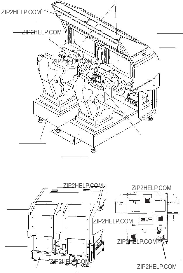
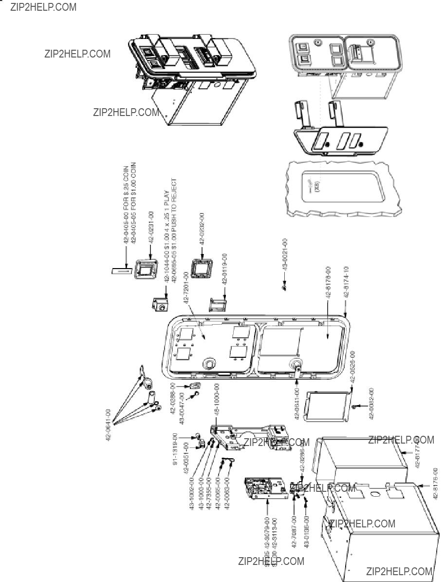
4. NAME OF PARTS
Coin chute door
Cashbox door
REAR CABINET
FIG. 4 a OVERVIEW
Effect switch
AC unit
FIG. 4 c REAR VIEW
FIG. 4 b
TABLE 4

5. ACCESSORIES
When transporting the machine, make sure that the following parts are supplied.
The printer is available in this product as an optional. The printer prints Player's game results on the paper exclusively used for this product. Contact where you purchased the product from and mention the following Kit No. for an order. Detailed installation method is explained in the Kit Manual contained in the Kit.
KIT NO. :
TABLE 5 ACCESSORIES
Figures
If Part No. has no description, the Number has not been registered or can not be registered. Such a part may not be obtainable even if the customer desires to purchase it. Therefore, ensure that the part is in safekeeping with you.
AC Cable (Power Cord)
Used for installation, see 4 of Section 6.
SERVICE MANUAL 420-6508-01( 1 )
TAMPERPROOF???WRENCH
M8
TOOL
CORD CLAMP
Used for securing the power cord.
see 4 of Section 6.

VOL CONT
see Section 9, 11, 12.
TAMPERPROOF???SCREW
Used for installing
BILLBOARD.
see 2 of Section 6.
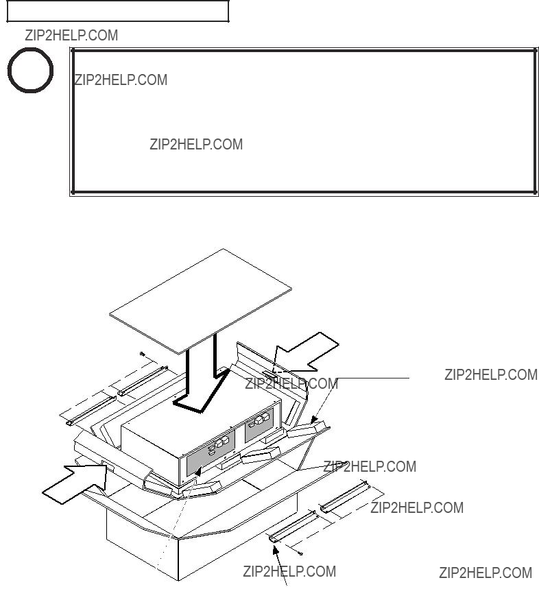
HOW TO USE THE CARTON BOX
STOP
IMPORTANT!
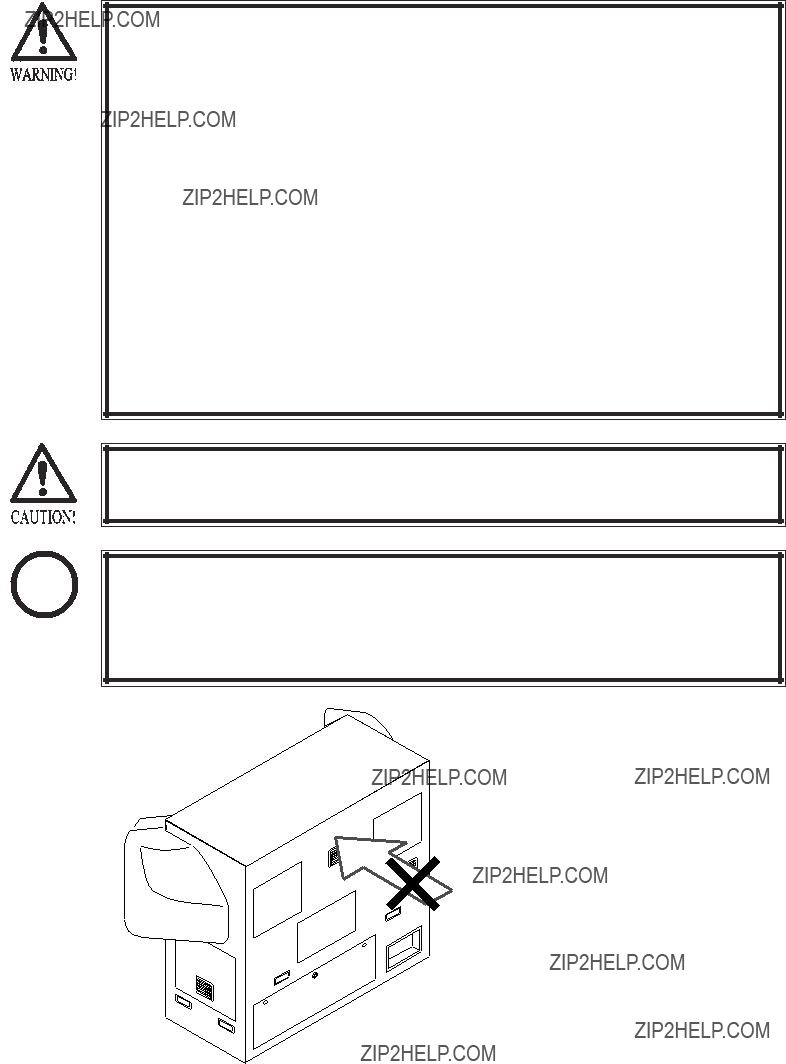
When requesting for the replacement/repair of this product's Game Board (NAOMI BOARD), follow the instructions below. Transporting the Game Board in an undesignated status is unacceptable. An erroneous handling can cause parts damage.
???Put the Game Board in the Carton Box together with the Shield Case. Do not unnecessarily disassemble nor remove parts.
???By paying careful attention to the direction shown by the following Figure, put the Shield Case in the Carton Box.
GRIP
FILTER BD side.
Ensure that the direction in which the Shield Case is packed is correct.
GRIP
Enfold the Shield Case with the packing material shown, and put it in the carton box. Positioning the Shield Case upside down or packing in the manner different from what is shown in this Figure can cause the Game Board and other parts to be damaged.
6.ASSEMBLING AND INSTALLATION
???Perform assembly work by following the procedure herein stated. Failing to comply with the instructions can cause electric shock hazard.
???Perform assembling as per this manual. Since this is a complex machine, erroneous assembling can cause an electric shock, machine damage and or not functioning as per specified performance.
???When assembling, be sure to use plural persons. Depending on the assembly work, there are some cases in which working by one person alone can cause personal injury or parts damage.
???Ensure that connectors are accurately connected. Incomplete connections can cause electric shock hazard.
???Be careful so as not to damage wirings. Damaged wiring can cause electric shock and short circuit hazards.
???In the case the cabinet is separated into the front and rear portions, do not push the upper rear part of the front cabinet. Failure to observe this causes the front cabinet to fall down towards the monitor side and result in accidents and injury to persons. When moving the front cabinet in the above case, be sure to push it from side directions and move it by 2 or more persons for safety.
???This work should be performed by the Location's Maintenance Man or Serviceman. Performing work by
???Provide sufficient space so that assembling can be performed. Performing work in places with narrow space or low ceiling may cause an accident and assembly work to be difficult.
When handling plastic parts, use care. Do not give a shock or apply excessive load to the fluorescent lamps and plastic parts. Failure to observe this can cause parts damage, resulting in injury due to fragments, cracks and broken pieces.
When carrying out the assembling and installation, follow the following
1
2
3
4
5
6
ASSEMBLING THE CABINET
INSTALLING THE CENTER ROOF AND THE BILLBOARD
SECURING IN PLACE (ADJUSTER ADJUSTMENT)
POWER SUPPLY CONNECTION
TURNING POWER ON
ASSEMBLING CHECK
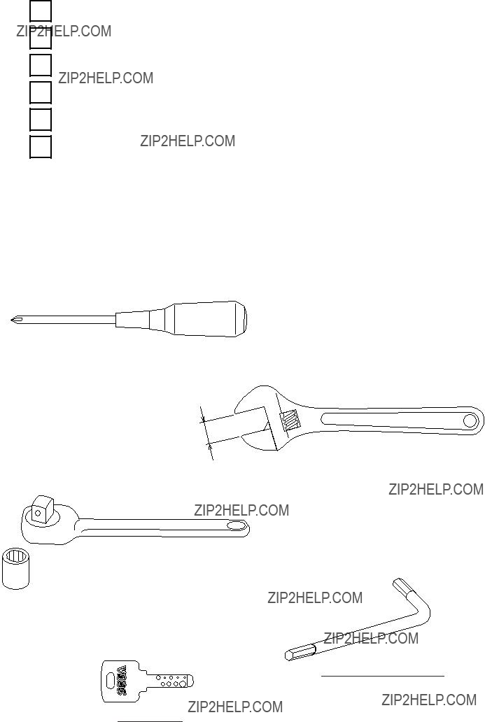
The master key (accessories) in addition to the tools such as a Phillips type screwdriver, wrench for M16 hexagon bolt, socket wrench, Ratchet Handle for M6, M8 hexagon bolt, Tamperproof???wrench (accessories) are required for the assembly work.
Phillips type screwdriver
24mm
WRENCH (for M16 hexagon bolt)
SOCKET WRENCH,(for M6,M8 hexagon bolt)
RATCHET HANDLE
TAMPERPROOF???WRENCH
KEY MASTER
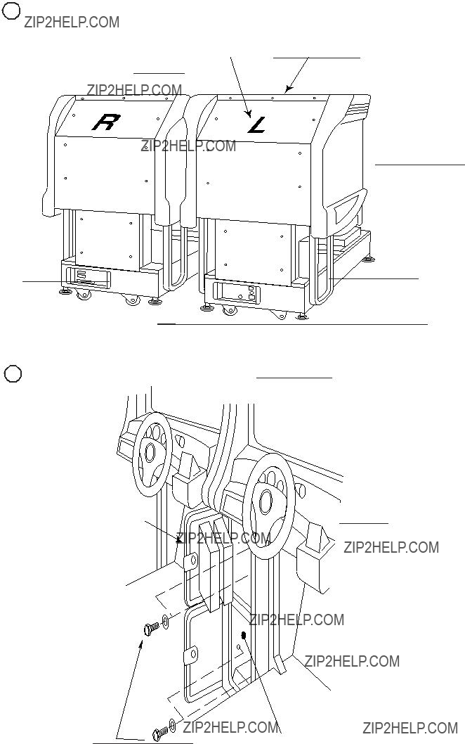
1Install the Joint Bracket L and 2 Joint Bracket R to the both sides of Front Cabinet, and 2 Joint Pipes to the inside. At this time, temporarily install the Joint Brackets L and R.
JOINT BRACKET R
JOINT PIPE
Hexagon Bolt(2 each)
M8 X 30,w/spring washer, flat washer used.
2Connect the wiring from the Front Cabinet to the Rear Cabinet.
Connect the Earth.
REAR CABINET side
SCREW (1)
M4 X 8,w/flat & spring washers
FRONT CABINET side

3Insert the Front Cabinet's Joint pipes into the Rear Cabinet's square holes to fit both cabinets tight. Be sure to perform this work by 2 or more workers. Also, be careful so as not to pinch the wiring.
4 Secure the joint portion of the Cabinets with 6 Hexagon Bolts. Firmly secure the Joint Brackets L&R, respectively.
5 By using Joint Plate Center, secure 


 the joint portion of the Cabinets
 with 4 Truss screws and Hexagon


 Bolts.
M8 X 20,w/spring washer, flat washer used.
TRUSS SCREW (4)
M4 X 16
FIG. 6. 1 c
2Put each of Roof Nut Plates F & R on to the fixed portion of the Center Roof front and rear and secure with 3 Truss screws for each.
3Remove the Shipping Bracket Rear from the Rear Cabinet's ceiling. Remove the 2 pairs of Tamperproof screws and Hexagon Bolts.
4Secure the Billboard with the 2 Tamperproof screws (separately packed) and the 2 flat washers which previously secured the Shipping Bracket Rear.
ROOF NUT PLATE F
CENTER ROOF
ROOF NUT PLATE R
BILLBOARD
TAMPERPROOF SCREW (2)
M8 X 30
S H I P P I N G
BRACKET REAR
TAMPERPROOF SCREW (2)
M8 X 30,flat washer used.
FIG. 6. 2
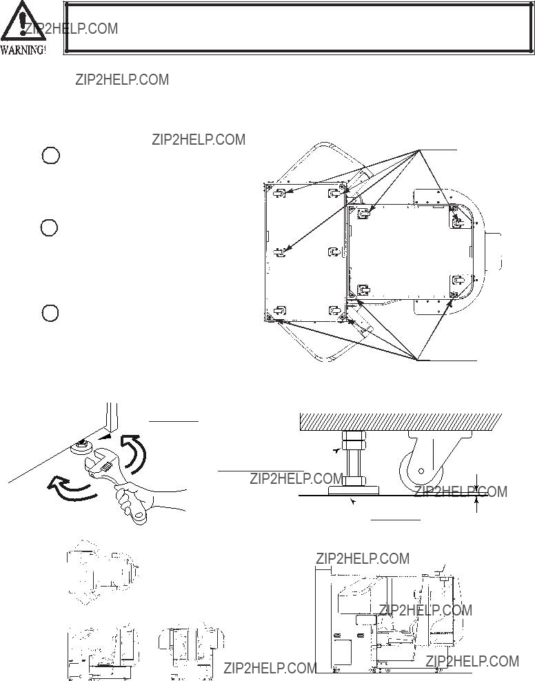
Make sure that all of the adjusters are in contact with the floor. If they are not, the cabinet can move and cause an accident.
This product has 8 casters (4 for Front Cabinet, 4 for Rear Cabinet) and 8 Adjusters (4 for Front Cabinet, 4 for Rear Cabinet). (FIG. 6. 3a) When the installation position is determined, cause the adjusters to come into contact with the floor directly, make adjustments in a manner so that the casters will be raised approximately 5mm. from the floor and make sure that the machine position is level.
1Transport the product to the installation position. Be sure to provide adequate space allowing the player to get on and off.
2Have all of the Adjusters make contact with the floor. Adjust the Adjuster's height by using a wrench so that the machine position is kept level.
3After making adjustment, fasten the Adjuster Nut upward and secure the height of Adjuster (FIG. 6. 3 b).
CASTER
ADJUSTER
FIG. 6. 3 a BOTTOM VIEW
ADJUSTER
CASTER
FASTEN UPWARD.
Approx.5mm
 ADJUSTER
FIG. 6. 3 b ADJUSTER
200mm
2345
1234 5
1234 5
1234 5
1234 5
1234 5
1234 5
1234 5
1234 5
1234 5
1234 5
1234 5
1234 5
1234 5
1234 5
1234 5
1234 5
1234 5
1234 5
1234 5
1234 5
1234 5
1234 5
1234 5
1234 5
1234 5
1234 5
1234 5
1234 52345678901234567890123456789012123456789012
1234 5234567890123456789012345678901212345678901
1234 5234567890123456789012345678901212345678901
1234 5234567890123456789012345678901212345678901
FIG. 6. 3 c
Refer to this Fig. (Scale:1/100) for the layout of the place of installation.
FIG. 6. 3 d
Be sure to provide space as shown between the Air Vent and the wall surface.

???Be sure to independently use the power supply socket outlet equipped with an Earth Leakage Breaker. Using a power supply without an Earth Leakage Breaker can cause a fire when electric leakage occurs.
???Ensure that the "accurately grounded indoor earth terminal" and the earth wire cable are available (except in the case where a power cord plug with earth is used). This product is equipped with the earth terminal. Connect the earth terminal and the indoor earth terminal with the prepared cable. If the grounding work is not performed appropriately, customers can be subjected to an electric shock, and the product's functioning may not be stable.
???Ensure that the power cord and earth wire are not exposed on the surface (passage, etc.). If exposed, they can be caught and are susceptible to damage. If damaged, the cord and wire can cause electric shock and short circuit accidents. Ensure that the wiring position is not in the customer's passage way or the wiring has protective covering.
???After wiring power cord on the floor, be sure to protect the power cord. Exposed power cord is susceptible to damage and causes an electric shock accident.
The AC Unit is mounted on the rear of the machine. The AC Unit has Main SW, Circuit Protector and the Inlet which connects the Power Cord.
1 Ensure that the Main SW is OFF.
MAIN SW
EARTH TERMINAL
Connect with the indoor earth terminal.
Main SW off
CIRCUIT PROTECTOR
AC Cable (Power Cord)

2Connect one end of the earth wire to the AC Unit earth terminal, and the other end to the indoor earth terminal. The AC Unit earth terminal has a Bolt and Nut combination. Take off the Nut, pass the end of earth wire through the Bolt, and fasten the Nut.
Note that the Earth Wire is incorporated in the Power Cord for the Areas of AC 120V (USA) and AC 220??`240V, and therefore, this procedure is not necessary.
Connect the Earth Wire to the Earth Terminal.
FIG. 6. 4 b Earth Wire Connection
3Firmly insert the power plug into the socket outlet. Insert the opposite side of Power Cord plug to the AC Unit's connector ("INLET").
4Perform wiring for the Power Cord and Earth Wire. Install protective covering for the Power Cord and Earth Wire.
Wiring Cover
FIG. 6. 4 c Connecting Power Cord and Earth Wire
In case the Power Plug is apt to come out of place, secure the
Power Cord to the periphery of the AC Unit with the Cord
Clamp (an accessory).
HOW TO USE THE CORD CLAMP

5 TURNING POWER ON
Turn the Main SW of AC Unit ON to turn power on. When the power is turned on, the fluorescent lamps of the left & right of Seat in the Rear cabinet, the back, and the inside the Billboard light up. The screen displays the starting of Naomi System and then proceeds to ADVERTISE mode. During this time, the machine automatically performs Power On check. Do not touch the machine until Power On check is finished and ADVERTISE mode is displayed on the screen. In the Power On check, the steering wheel turns left and right, then returns to the centering position and stops. In this check, the values of V.R. inside the control panel are corrected. Until the check is finished (the steering wheel stops automatically), do not touch the steering wheel or play the game. If you do, the steering wheel reaction during the game (reaction at the time of a
FIG. 6. 5

6 ASSEMBLING CHECK
In the TEST mode, ascertain that the assembly has been made correctly, IC BD. is satisfactory, and the screen adjustment is appropriate. For details, refer to the SERVICE MANUAL. In the test mode, perform the following test:
??? MEMORY TEST
The
??? CRT TEST
The screen on which the monitor is adjusted is displayed.
??? INPUT TEST
Each switch and V.R. are tested.
??? OUTPUT TEST
The lamp, motor, etc. are tested.
??? SOUND TEST
The sound related BD and wiring connections are tested. Be sure to check if the sound is satisfactorily emitted from each speaker and the sound volume is appropriate.
Perform the above inspections also at the time of monthly inspection.

7. PRINTER (OPTIONAL)
STOP
IMPORTANT!
Refer to this section only when the Printer (optional) is attached.
???Be sure to turn off power unless otherwise specified before performing work. Performing work on the energized machine can cause hands or fingers to be pinched in or in jured due to the machine's sudden move.
???Do not touch undesignated places. Failure to observe this may cause a burn due to the Head's high temperature when printing.
???When performing work that uses the cutter, be very careful so as not to cut hands or fingers.
???Be sure to use the exclusively used paper and a Cleaning Pen. Using unspecified parts can cause malfunctioning and/or a damage to parts.
???Be sure to use the new roll paper unwrapped immediately before the use. Using the roll paper previously unwrapped and left for a while can cause malfunctioning due to deterioration resulted from humidity.
???When setting the paper with the power on, if the paper volume is small, the Printer might not accept the set roll paper. In that case, follow the "SETTING THE PAPER WITH THE POWER OFF" procedures to set the paper.
When the Printer is malfunctioning, the 2 Error Lamps attached to the Rear Cabinet back side flash or light up. The Lamps flash when the paper is exhausted and light up when the trouble is other than the running out of paper.
When placing an order, contact where you purchased the product or the Printer Kit from in stating the following part number and the description.
The following set (Part Number:
PART NUMBER:
7 - 1 OPERATION WITH THE PRINTER ATTACHED
The Printer which prints Player's Driving Data and the GAME BOARD do not keep the data to be printed. When "PRINTING CAN NOT BE DONE" is displayed or the PRINTER is set to OFF in the Test mode, printing can not be done as the product does not have such system as printing out the data at a later operation. Therefore, as for the printing, instruct the Player to pay attention to the following.
???Although YES is selected to the "PRINT OUT?" question displayed on the monitor, printing can not be done if a credit worth coin is not inserted within the time limit. Such credit (coin) as inserted after the time limit is regarded as a game play credit.
???If the Printer malfunctions such as a paper jam occurred during printing, the printing for the Driving Data can not be done as neither the Printer nor the ROMs on the GAME BOARD keeps the data.
???When "PRINTING CAN NOT BE DONE" is displayed or the PRINTER is set to OFF in the Test mode, printing can not be done as the product does not have such system as printing out the data at a later execution.

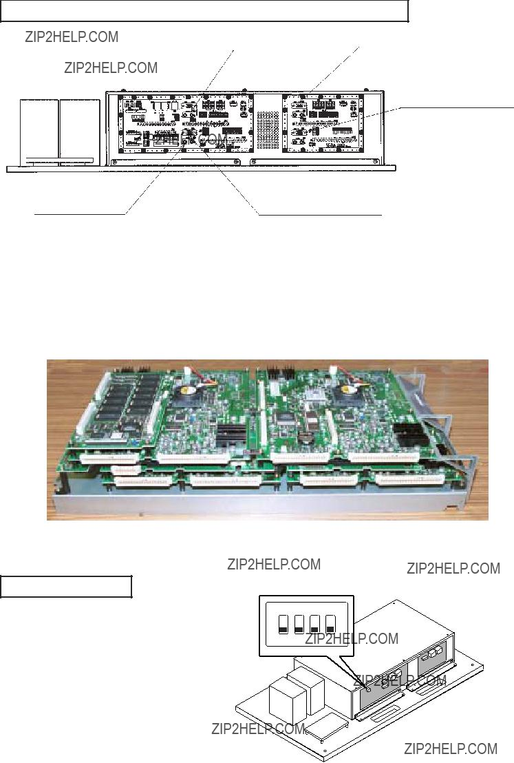
DIP SW SETTING
The Printer has 2 DIP Switches. To avoid malfunctioning, use the Switches as adjusted at the time of shipment.
Setting at the time of shipment
DIP SW
FIG. 7. 1
7
The 2 red Lamps at the Rear Cabinet back side flash indicating the PAPER END Error under normal operation. Prepare the new Roll Paper exclusively used for the product and the Master Key. To set the Roll Paper, perform Printer's initialization to remove the cause of the error.
Turn off power or enter into the Test Mode to perform the initialization. Explanations for setting the Roll Paper in cases of power on and off are given as follows. Further, when the Roll Paper is set after the Printer Kit is installed, performing work with the power off is necessary as the power is turned off when installing the Kit. The Roll Paper has Marks indicating position in order to print and cut properly. The Mark indicating the end of paper appears at the end of Roll Paper. The Printer's Sensor detects the Mark and interprets it as the end of Roll Paper. At the beginning of Cabinet's installation, the red Lamps light up as the Mark indicating the end of Paper is not detected.
1Enter into the TEST Mode and have PRINTER TEST screen displayed on the monitor. "ERROR!!" next to the MESSAGE and "PAPER END" next to the WARNING are displayed on the monitor.

 PRINTER TEST
MESSAGE : ERROR !!
ERROR :
WARNING : PAPER END
STATUS :
COUNTER :
INIT
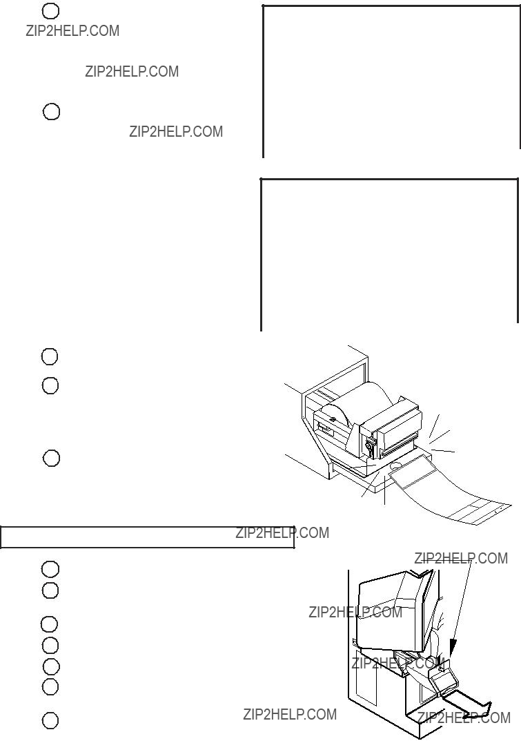
2Unlock with the Master Key and remove the Printer Door.
3 Draw the ASSY Printer toward you.
FIG. 7. 2 a
ASSY Printer
FIG. 7. 2 b

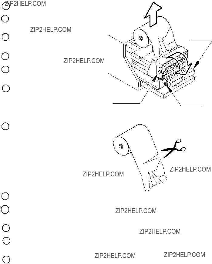
4 Pull up the Head Up Lever.
5 Take out the roll shaft from the Printer.
6 Pass the shaft through the core of the new Roll Paper.
7Install the roll shaft in which the paper is inserted into the unit. Make sure to put the Roll Paper on to the correct position.
Roll shaft
New Roll Paper
Head Up Lever
FIG. 7. 2 c
8 Insert the paper tip in to the roll paper insertion slot. Feed the Roll Paper tip through the exit slot straight by hand. At this time, if the Paper tip comes out in excess of the exit slot, Printer performs automatic feeding and cuts the Paper after feeding about one page long.
9 Push down the Head Up Lever.
FIG. 7. 2 d
Push down the Head Up Lever.
The feeding point of the Roll Paper tip.
FIG. 7. 2 e
10Select and execute the INIT in the PRINTER TEST. The "PRINTER INIT!!" message flashes next to "MESSAGE" on the monitor and then goes off. The Printer's initialization is finished.
11Select and execute the "POSITION SET." "NOW PRINTING" message is displayed next to the "MESSAGE" on the monitor and then goes off. The Printer starts automatic feeding of the paper (AUTO LOADING) and then cuts the paper automatically. If the Paper tip position is appropriate, the automatic feeding's movement is slight and the paper cutting may not be done. Before executing the POSITION SET, the paper position can be adjusted by executing
12
13Push the ASSY PRINTER up to the point the PRINTER reaches the Securing Part in the innermost of the unit.
14 Lock the Printer Door to secure.
 PRINTER TEST
MESSAGE : PRINTER INIT!
ERROR :
WARNING :
STATUS :
COUNTER :
POSITION SET
 PRINTER TEST
MESSAGE : NOW PRINT-
ING
ERROR :
WARNING :
STATUS :
COUNTER :
INIT
In case that the paper tip comes out in excess of the exit slot, Paper is cut after Printer feeds Paper one page long.
FIG. 7. 2 f
SETTING THE PAPER WITH THE POWER OFF
Printer Door
1 Turn off power.
2 Unlock with the Master Key and remove the Printer Door.
3 Draw the ASSY Printer toward you.
4 Pull up the Head Up Lever.
5 Take out the roll shaft from the Printer.
6 Pass the shaft through the core of the new Roll Paper.
7Install the roll shaft in which the paper is inserted into the unit. Make sure to put the Roll Paper on to
Note that this Roll Paper holder will not be seen when setting the new Paper for the first time.
8Insert the paper tip in to the Roll Paper insertion slot. Feed the Roll Paper tip through the exit slot straight by hand. At this time, if the Paper tip is in excess of the feeding point, the automatic feeding of Paper is performed and the Paper is cut after feeding about one page long.
9 Push down the Head Up Lever.
The feeding point of the Roll
Paper tip.
FIG. 7. 2 i
Push down the Head Up Lever.
10Turn on power. The Printer starts automatic feeding of the paper (AUTO LOADING) and then cuts the paper automatically. If the Paper tip position is appropriate as per previous procedure, the automatic feeding's movement is slight and the paper cutting may not be done.
11Push the ASSY PRINTER into the point the PRINTER reaches the securing part in the innermost of the unit.
12Lock the Printer Door to secure.

7 - 3 CLEANING OF THE PRINTER HEAD
Each time the Roll Paper is supplied, clean the Printer Head. Prepare the cleaning pen which is included in the Print Paper Set exclusively used for this product and a Master Key.
1 Turn off power.
2Unlock with the Master Key and remove the Printer Door.
3 Draw the ASSY Printer toward you.
4 Push up the Head Up Lever.
5 Remove the Roll Paper.
6Push down the Cutter Lever and open the Auto Cutter.
Roll Paper
Auto Cutter
Head Up Lever
Cutter Lever
FIG. 7. 3 a
7 By using the cleaning pen, clean the printer head.
Use the exclusively used
Cleaning Pen.
FIG.7. 3 b
FIG. 7. 3 c
8 Lift the Auto Cutter and lock.
9 Set the Roll Paper.
10Push down the Head Up Lever and turn on power. The Printer performs automatic feeding and cutting of the paper.
11 Put the ASSY Printer and lock the printer door to secure.
4 Pull up the Head Up Lever.
5 Push down the Cutter Lever and open the Auto Cutter.
6 Remove the jammed paper.
Head Up Lever
Auto Cutter
Cutter Lever
FIG. 7. 4 a
7 Eliminate the warped, wrinkled paper due to the paper jam. At this time, after eliminating the paper, any portion can come to the tip as the Printer automatically adjusts the Paper position by feeding and cutting the Paper.
FIG. 7. 4 b
8 Lift the Auto Cutter and lock.
9Insert the paper tip in to the roll paper insertion slot. Feed the Roll Paper tip through the exit slot straight by hand until the paper tip can be seen from the exit slot.
10 Pull up the Head Up Lever.
11 Turn on power. The Printer performs automatic feeding (AUTO LOADING) and cutting of the paper.
12 Put the ASSY Printer and lock the printer door to secure.
8.PRECAUTIONS TO BE HEEDED WHEN MOVING THE MACHINE
???When moving the machine, be sure to unplug the power plug. Moving the machine with the plug as is inserted can damage the power cord and cause fire and electric shock hazards.
???When moving the machine on the floor, retract the Adjusters and ensure that Casters make contact with the floor. During transportation, pay careful attention so that Casters do not tread power cords and earth wires. Damaging the power cords can cause electric shock and short circuit hazards.
???When lifting the cabinet, be sure to hold the grip portions or bottom part. Lifting the cabinet by holding other portions can damage parts and installation portions due to the empty weight of the cabinet, and cause personal injury.
???In the case the cabinet is separated into the front and rear portions, do not push the upper rear part of the front cabinet. Failure to observe this causes the front cabinet to fall down towards the monitor side and result in accidents and injury to persons. When moving the front cabinet in the above case, be sure to push it from side directions and move it by 2 or more persons for safety.
???Do not insert the fork to places other than designated when using a Forklift to transport the machine.
Failure to observe this could cause falling down and injury resulting from falling down.
STOP
IMPORTANT!
Do not push
???When transporting the product in places with steps, disassemble into each unit before transporting. Inclining the product in an as is assembled condition or placing the cabinet in places with steps can damage the unit's joining portions.
???To protect surface, do not directly apply a rope to the surfaces of product. Use protective materials to the places the rope is applied to.
In the case the cabinet is separated into the front and rear portions, do not push the upper rear part of the front cabinet.
FIG. 8 a

When transporting the product in places with steps or
GRIP
23456789012345678901234567890121234567890123456789012345678901212345678901234567890123456789012123456789012345
2345678901234567890123456789012123456789012345678901234567890121234567890123456789012345678901212345678901234
2345678901234567890123456789012123456789012345678901234567890121234567890123456789012345678901212345678901234
2345678901234567890123456789012123456789012345678901234567890121234567890123456789012345678901212345678901234
2345678901234567890123456789012123456789012345678901234567890121234567890123456789012345678901212345678901234
23456789012345678901234567890121234567890123456789012345678901212345678901234567890123456789012123456789012345
Have casters make contact with the floor.
FIG. 8 b
Do not push
FIG. 8 c

Precautions concerning applying a rope.
SHIPPING BRACKET REAR
FIG. 8 d
???Do not apply a rope to Handle or Lever.
???Use protective materials to the places the rope is applied to.
Caution when transporting the machine
FIG. 8 e

9.HANDLE MECHA
???Before starting to work, ensure that the Power SW is OFF. Failure to observe this can cause electric shock or short circuit.
???Use care so as not to damage wirings. Damaged wiring can cause electric shock or short circuit.
???Do not touch undesignated places. Touching places not designated can cause electric shock or short circuit.
???This work should be performed by the Location's Maintenance Man or Serviceman. Performing work by
???Do not insert hand into the mechanism so as not to cause hand and fingers pinched in. Failure to observe this can cause a serious injury such as a fracture.
???When performing work such as parts replacement other than those specified in this manual, be sure to contact where you purchased the product from and confirm the work procedures and obtain precautions prior to performing work. Inappropriate parts replacement and/or installing with erroneous adjustment can cause an overload or the parts to come into contact, resulting in an electric shock, a short circuit, and a fire.
IMPORTANT!
9 - 1 ADJUSTING OR REPLACING THE V.R.
In cases the Steering operability is poor and the adjustment of VOLUME SETTING in the TEST mode is ineffective, the causes may be the Volume Gear's mesh failure and or Volume malfunctioning. By using the following procedure, adjust Volume gear mesh, or replace the Volume. In this product, when the Steering Wheel is moved fully left/right, if the Volume shaft is rotating within the movable range, the Volume is not feared to be damaged. Secure the Volume in the manner the Volume shaft is oriented as shown and the gears are appropriately engaged when the steering wheel is in the centering position allowing the car to go straight forward.
ADJUSTING THE VOLUME
Be sure to use 2 workers in adjust- ing the Volume, one is for operat- ing the Steering Wheel and the other one for performing the adjustment.
1 Turn off power.
2Take out 4 Truss screws to remove the Rear Lid from the back of Front Cabinet. At this time, carefully support the Rear Lid as taking out the 4 Truss screws can cause the Rear Lid to drop.
REAR LID
PHOTO 9. 1 a
TRUSS SCREW (4)
M4 X 16

3Perform the adjustment while another person is securing the Steering Wheel in the centering position.
4The V.R. is on the VR BASE (a white, plastic made part). Loosen the 2 screws which secure the VR BASE and adjust the angle and appropriateness of gear mesh by moving the VR BASE.
5Adjust to an appropriate mesh by securing the Steering Wheel in the direction allowing the car to advance straight forward and ensuring the "D" CUT FACE of the Volume shaft is oriented as shown.
6 Tighten the 2 screws to secure the VR BASE.
VR BASE
SCREW (2)
M4 X 12,w/flat & spring washers
"D" CUT FACE
FIG. 9. 1 a
7 Turn on power.
8 Set the Center Value of the Volume in the TEST mode.
9In the TEST mode, check to see if the Volume Value varies smoothly in accordance with the steering wheel operation.

REPLACING THE VOLUME
1Disconnect the connector from the Volume.
2Take out 2 screws to remove the Volume together with VR BASE from the HANDLE MECHA.
SCREW (2)
M4 X 12,w/flat & spring washers
VR BASE
PHOTO 9. 1 b
3Take out 2 screws from the VR BASE reverse side to remove the Volume together with VR Bracket from the VR BASE.
4Remove the Volume from VR Bracket and replace.
TRUSS SCREW (2)
M4 X 12
PHOTO 9. 1 c

5After replacing the Volume, engage the gears at the angular position shown and fix the VR Bracket.
VR BASE
SCREW(2)
M4 X 12,w/flat & spring washers
FIG. 9. 1 b
7 Set the Center Value of the Volume in the TEST mode.
8In the TEST mode, check to see if the Volume Value varies smoothly in accordance with the steering wheel operation.
9 - 2 GREASING
VOLUME GEAR MESH PORTION
Apply greasing to gear mesh portions once every 3 months.
Use GREASE MATE
(SEGA PART NO.
PHOTO 9. 2
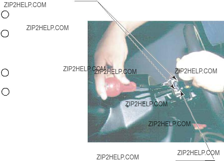
9 - 3 REPLACING PADDLE (WING) SHIFT SWITCH
In case the Paddle Shift operability is poor, malfunctioning of or a damage to the Microswitch inside the Paddle Shift can be considered.
1 Turn off power.
2Take out 2 Truss screws for each to remove Boss Cover Upper and Lower.
3Disconnect the wiring connected to the Microswitch.
PADDLE SHIFT
BOSS COVER
TRUSS SCREW (2 each)
M4 X 8
BOSS COVER
PHOTO 9. 3 a
SCREW (2)
M3 X 16
4Take out 2 screws to replace the Microswitch.
5Adjust Microswitch's actuator to an angular position so as not to touch the Switch when operating the Shift Lever.
6 Fasten 2 screws to secure the Microswitch.
7 Check to ensure that the Switch goes ON and OFF in consistency with the operation.
MICROSWITCH
PHOTO 9. 3 b

10.
???Before starting to work, ensure that the Power SW is OFF. Failure to observe this can cause electric shock or short circuit.
???Use care so as not to damage wirings. Damaged wiring can cause electric shock or short circuit.
???Do not touch undesignated places. Touching places not designated can cause electric shock or short circuit.
???This work should be performed by the Location's Maintenance Man or Serviceman. Performing work by
???When performing work such as parts replacement other than those specified in this manual, be sure to contact where you purchased the product from. Confirm the work procedures and obtain precautions from where you purchased the product from prior to performing work. Inappropriate parts replacement and/or installation with erroneous adjustment can cause an overload or the parts to come into contact, resulting in an electric shock, a short circuit, and a fire.
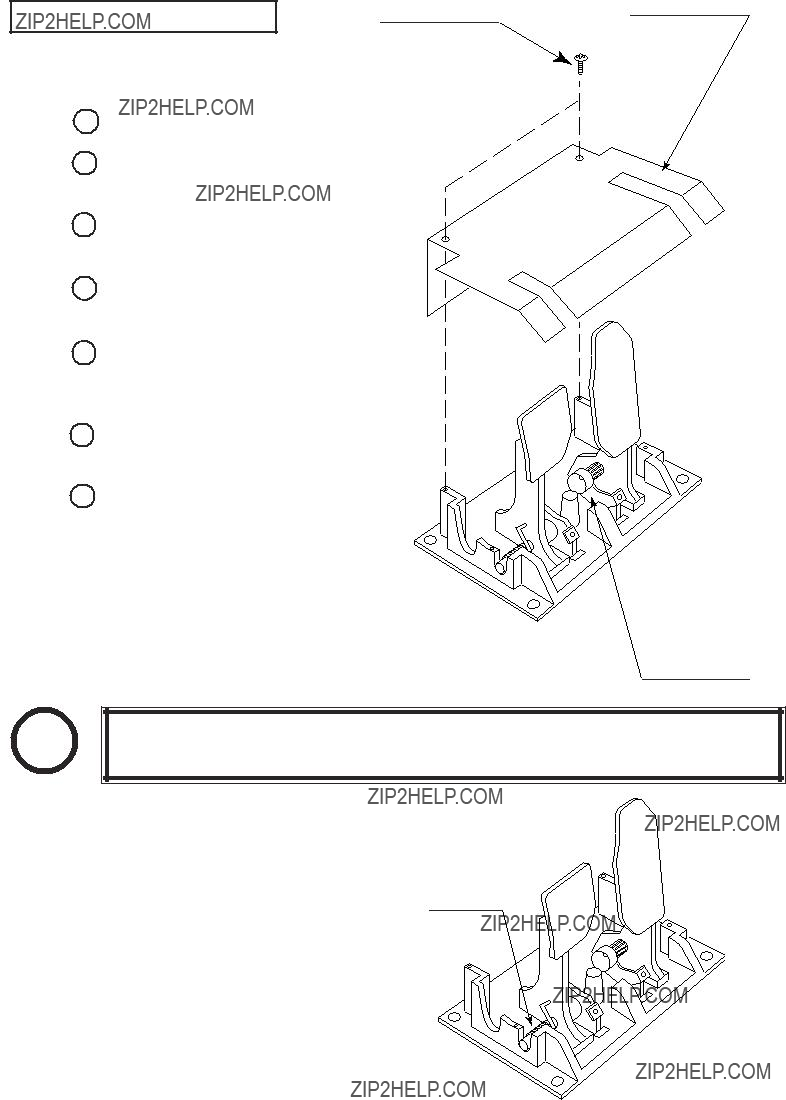
10 - 1 REMOVING THE SHIFT LEVER
1 Turn off power.
2 Take out 4 screws securing the EFFECT Switch.
3 Take out 5 Truss screws which secure the Console Cover.
TRUSS SCREW (4)
M4 X 12
CONSOLE COVER
EFFECT SWITCH

4 Disconnect a connector.
5 Take out 4 Hexagon Bolts.
HEXAGON BOLT (4)
M8 X 40,w/flat & spring washers
Disconnect the connector
PHOTO 10. 1 b
PHOTO 10. 1 c
6Lift the
7Disconnect 2 connectors to remove the
PHOTO 10. 1 d
Disconnect the connector

10 - 2 REPLACING THE SWITCH
In case
1Remove
2Disconnect the wiring connected to the Microswitch.
3Take out 2 screws to replace the Microswitch.
4Adjust Microswitch's actuator to an angular position so as not to touch the Switch when operating the Shift Lever.
5Fasten 2 screws to secure the Microswitch.
SCREW (2)
M2.3 X 10,w/flat & spring washers
MICROSWITCH
PHOTO 10. 2 a
6Check to ensure that the Switch goes ON and OFF in consistency with the operation.
SCREW (2)
M2.3 X 10,w/flat & spring washers
MICROSWITCH
PHOTO 10. 2 b

11.ACCELERATOR & BRAKE
???Before starting to work, ensure that the Power SW is OFF. Failure to observe this can cause electric shock or short circuit.
???Use care so as not to damage wirings. Damaged wiring can cause electric shock or short circuit.
???Do not touch undesignated places. Touching places not designated can cause electric shock or short circuit.
???This work should be performed by the Location's Maintenance Man or Serviceman. Performing work by
???When performing work such as parts replacement other than those specified in this manual, be sure to contact where you purchased the product from. Confirm the work procedures and obtain precautions from where you purchased the product from prior to performing work. Inappropriate parts replacement and/or installation with erroneous adjustment can cause an overload or the parts to come into contact, resulting in an electric shock, a short circuit, and a fire.
If Accel. and Brake operation is not satisfactory, adjustment of Volume installation position or Volume replacement is needed. Also, be sure to apply greasing to the gear mesh portion once every 3 months.
11 - 1 ADJUSTING AND REPLACING THE V.R.
The appropriate value for both ACCEL. Volume and Brake Volume is under 30H when released and over C0H when stepped on. Check Volume values in the TEST mode. Since work is performed inside the energized cabinet, be very careful so as not to touch undesignated places. Touching places not specified can cause electric shock or short circuit.
1Take out the 2 truss screws and remove the Front Cover from the Accel. & Brake Unit
(FIG. 11. 1 a).
2Loosen the screw which secure the Potentiobase, and adjust the Volume value by moving the Base. (FIG. 11. 1 b)
3
4Perform Volume setting in the Volume setting mode.
TRUSS SCREW (2)
M4 X 8, chrome
REPLACING THE VOLUME
1 Turn the power off.
2Take out the 2 screws and remove the Potentiocover (FIG. 11. 1 c).
3Disconnect the connector of the Volume to be replaced.
4Remove the screw which secures the Potentiobase (FIG. 11. 1 b).
5Remove the Potentiobase together with the Volume as is attached. (FIG. 11. 1 c)
6Remove the Base and Gear to replace the Volume.
7Adjust the Volume as per the previous page after replacing.
TRUSS SCREW (2)
M4 X 8
POTENTIOCOVER
11 - 2 GREASING
FIG. 11. 1 c
POTENTIOBASE
STOP
IMPORTANT!
Be sure to use the designated grease. Using undesignated grease can cause parts damage.
Once every 3 months, apply greasing to the Spring and Gear mesh portion. For spray greasing, use GREASE MATE (PART No.
GREASING
FIG. 11. 2
12.CLUTCH PEDAL
???Before starting to work, ensure that the Power SW is OFF. Failure to observe this can cause electric shock or short circuit.
???Use care so as not to damage wirings. Damaged wiring can cause electric shock or short circuit.
???Do not touch undesignated places. Touching places not designated can cause electric shock or short circuit.
???This work should be performed by the Location's Maintenance Man or Serviceman. Performing work by
???When performing work such as parts replacement other than those specified in this manual, be sure to contact where you purchased the product from. Confirm the work procedures and obtain precautions from where you purchased the product from prior to performing work. Inappropriate parts replacement and/or installation with erroneous adjustment can cause an overload or the parts to come into contact, resulting in an electric shock, a short circuit, and a fire.
If the Clutch Pedal's operation is not satisfactory, the V.R. installation position adjustments or V.R. replacement is needed. Also, be sure to apply greasing to the V.R. Gear mesh portion and the 2 Springs once every 3 months.
12 - 1 REMOVING THE CRUTCH PEDAL
1 Turn off power.
2Take out 4 Hexagon Bolts. At this time, support the Clutch Pedal as taking out the bolts can cause the Clutch Pedal to fall.
PHOTO 12. 1 a
HEXAGON BOLT (4)
M8 X 30,w/spring washer

3Take out a screw to remove the earth wire which is connected to the Clutch Pedal Mechanism side.
SCREW (1)
M4 X 8,w/flat & spring washers
EARTH
PHOTO 12. 1 b
4Disconnect the connector to remove the Clutch Pedal.
Disconnect the connector
PHOTO 12. 1 c

12 - 2 VOLUME ADJUSTMENT/REPLACEMENT
The appropriate value of Crutch Volume is under 30H when released and over C0H when stepped on. Check Volume values in the TEST mode. Since work is performed inside the energized cabinet, be very careful so as not to touch undesignated places. Touching places not specified can cause electric shock or short circuit.
ADJUSTING THE VOLUME
1 Loosen 2 screws which secure the Volume Bracket to adjust the gear mesh.
2 Tighten the 2 screws.
3In the TEST mode, check to ensure that the Volume Values are within the appropriate range and vary smoothly in consistency with the Pedal operation.
VR BRACKET
SCREW (2)
M4 X 8,w/flat & spring washers
PHOTO 12. 2
REPLACING THE VOLUME
1 Disconnect the connector from the Volume.
2Take out 2 screws to remove the Volume together with the VR Bracket from the Crutch Pedal Mechanism.
3 Remove the Volume from the VR Bracket to replace.
4 After replacing the Volume, engage the gears and fix the VR Bracket.
5In the TEST mode, check to ensure that the Volume Values are within the appropriate range and vary smoothly in consistency with the Pedal operation.
12 - 3 GREASING
STOP
IMPORTANT!
Be sure to use the designated grease. Using undesignated grease can cause parts damage.
Once every 3 months, apply greasing to the Spring and Gear mesh portion. For spray greasing, use GREASE MATE (PART No.
VOLUME GEAR MESH PORTION
SPRING
SPRING
PHOTO 12. 3

13. COIN SELECTOR
HANDLING THE COIN JAM
If the coin is not rejected when the REJECT button is pressed, open the coin chute door and open the selector gate. After removing the jammed coin, put a normal coin in and check to see that the selector correctly functions.
CLEANING THE COIN SELECTOR
???Never apply machine oil, etc. to the Coin Selector.
???After cleaning the Coin Selector, insert a regular coin in the normal working status and ensure that the Selector correctly functions.
1 The coin selector should be cleaned once every
3 months. When cleaning, follow the procedure below:
2Turn the power for the machine OFF. Open the coin chute door.
Open the gate and dust off by using a soft brush
(made of wool, etc.).
3Remove and clean smears by using a soft cloth dipped in water or diluted chemical detergent
and then squeezed dry.
4Remove the CRADLE.
When removing the retaining ring
(E ring), be very careful so as not to bend the rotary shaft.
5 Remove stain from the rotary shaft and shaft receiving portions by wiping off with a soft cloth, etc.
6 After wiping off as per 5 above, further apply a dry cloth, etc. to cause the coin selector to dry completely.
GATE
FIG. 13 a
CRADLE
FIG. 13 b
COIN INSERTION TEST
Once every month, when performing the Coin SW Test, simultaneously check the following:
Does the Coin Meter count satisfactorily? Does the coin drop into the Cashbox correctly? Is the coin rejected when inserted while keeping the Reject Button pressed down?
Insert a coin while keeping the Reject Button pressed down and check if it is rejected.
COIN METER
FIG. 13 c

com.seuservice.www
46
ELECTRONICS CORPORATION
2701 N. KILDARE CHICAGO, IL 60639
14
1 2
29
9
10
8
E
C
A
5
G
H
M
OVER/UNDER MINI DOOR
2 ENTRIES WITH BILL
VALIDATOR BOTTOM DOOR
& SPECIAL ENCLOSURE
Guardian Hasp
Tom HappPh:

OPTIONAL DOLLAR BILL ACCEPTOR
 THE COIN DOOR ASSEMBLY USED ON F355 challenge DX TYPE COMES
EQUIPPED TO ACCEPT A DOLLAR BILL ACCEPTOR. ALL NEEDED
WIRING CONNECTIONS ARE CONVIENENTLY LOCATED INSIDE THE
GAME FOR THIS APPLICATION.
 THE COIN DOOR CAN ACCCOMMODATE THE FOLLOWING VALIDATOR(S):
The frame and cashbox enclosure on this coindoor has been modified to accomodate a Mars 2000 series upstacker. A 2000 series stacker can be added by simply remov- ing the
Note: Your game may have either Happ Controls Coin Door Assembly or the Wells Gardner Coin Door Assembly (not shown).
**Happ part number
Security Locking Bar/Bracket Set Part No.#
Modified Cash Box (For use when DBA installed) Part No. #
Plastic Cash Box - Full Size Part No. #

14. MONITOR
14 - 1 CAUTIONS AND WARNINGS CONCERNING THE SAFETY FOR HANDLING THE MONITORS Before handling the monitors, be sure to read the following explanations and comply with the caution/warning instructions given below. Note that the caution/warning symbol marks and letters are used in the instructions.
Indicates that handling the monitors erroneously by disregarding this warning may cause a potentially hazardous situation, which could result in death or serious injury.
Indicates that access to a specific part of the equipment is forbidden.
Indicates that handling the monitors by disregarding this caution may cause a potentially hazardous situation, which could result in personal injury and or material damage.
Indicates the instruction to disconnect a power connector or to unplug.
???When performing such work as installing and removing the monitor, inserting and disconnecting the external connectors to and from monitor interior and the monitor, be sure to disconnect the power connector (plug) before starting the work. Proceeding the work without following this instruction can cause electric shock or malfunctioning.
???Using the monitor by converting it without obtaining a prior permission is not allowed. SEGA shall not be liable for any malfunctioning and accident caused by said conversion.
???Primary side and Secondary side
The monitor's circuit which is divided into the Primary side and Secondary side, is electrically isolated. Do not touch the primary side, or do not touch both the primary side and the secondary side simultaneously. Failing to observe the instruction can cause electric shock and this is very dangerous. When making monitor adjustments, use a non- conductive driver and make adjustment without touching any part other than the Adjustment V. R. and knob. Also, be sure not to cause a
SECONDARY SIDE
(Chassis, CRT)
PRIMARY
SIDE
???
Some of the parts inside monitor are subject to
Approx. 10 kV
???Connecting the CRT and PCB
For combining the CRT and PCB, use the specified part No. to maintain the status of adjustments made at the factory. The anode of the CRT itself will be accumulatively charged as time elapses, generating
49www.seuservice.com

???Static Electricity
Touching the CRT surface sometimes causes you to slightly feel electricity. This is because the CRT surfaces are subject to static and will not adversely affect the human body.
???Installation and removal
Ensure that the Magnetizer Coil, FBT

For the purpose of static prevention, special coating is applied to the CRT face of this product. To protect the coating, pay attention to the following points. Damaging the coating film can cause electric shock to the customers.
???Do not apply or rub with a hard item (a rod with pointed edge, pen, etc.) to or on the CRT surfaces.
??? Avoid applying stickers, seals, etc. on the CRT face.
Aluminum Foil
???Do not remove aluminum foils from the CRT corners. Removing the aluminum foils can cause static prevention effects to be lowered.
14 - 2 CAUTIONS TO BE HEEDED WHEN CLEANING THE CRT SURFACES
Static preventive coating is applied to the CRT surfaces. When cleaning, pay attention to the following points. Peeling off of static preventive coat can cause electric shock.
???Remove smears by using a dry, soft cloth (flannels, etc.). Do not use a coarse gauze, etc.
???For smear removing solvent, alcohol (ethanol) is recommended. When using chemical detergent, be sure to follow instructions below:
???Dilute chemical detergent with water and dip a soft cloth in and then thoroughly wring it to wipe smears off.
???Do not use a chemical detergent containing an abradant, powder or bleaching agent.
???Do not use alkaline chemical detergents such as "glass cleaner" available on the market or solvents such as thinner, etc.
???Do not rub or scratch the CRT face with hard items such as brushes, scrub brush, etc.
Clean the CRT surfaces once a week. When cleaning, pay attention to the above caution so that the antistatic coating will not come off.

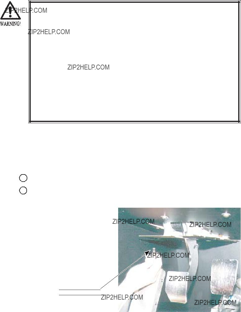
14 - 3 ADJUSTMENT METHOD
???Monitor adjustments have been made at the time of shipment. Therefore, do not make further adjustment without a justifiable reason. Adjusting the monitor which contains high tension parts is a dangerous work. Also, an erroneous adjustment can cause deviated synchronization and image fault, resulting in malfunctioning.
???When making adjustment, utilize a resinous Alignment Rod. Servicing with bare hand or using conductive tools can cause electric shock.
Remove the 2 screws from the Monitor Board Lid on top of the monitor, and the Adjustment Board appears.
TRUSS SCREW(2)
blackM4 X 10
Monitor Board Lid
PHOTO 14. 3
For adjustment, use the Resinous Adjustment Rod.
FIG. 14. 3

OPERATION
1Press the MODE button to display OSD. The
QUENCY.
051
OSD Display
IN/OUT/MODE
DOWN
UP
2Press the MODE button to select the adjustment item.
(Each time the MODE button is pressed, the OSD display shifts sequentially in order of
Press the DOWN button while pressing the MODE button to return the adjustment item to the preceding one.
3 Adjust with UP button and DOWN button.
4To exit from OSD, keep pressing the MODE button until the OSD display disappears.
???
The image' s vertical position is adjustable.
???
The horizontal image' s position is adjustable.
???
The vertical image size is adjustable.
???
The horizontal image size is adjustable.
???CONTRAST
Adjusts image contrast.
???BRIGHT
This adjusts the
???DEGAUSS
Degaussing is performed. Once degaussed, it takes approximately 4 minutes and 30 seconds to have degaussing function again. Wait until the lower OSD display indicates PLEASE.
???RESET
Reset the
14 - 4 CLEANING THE MONITOR GLASS
Removing the Monitor Glass requires complicated work. Clean the Front Glass only in the weekly cleaning. To clean the Reverse Glass of the Monitor and the CRT Surface, removing the Monitor Glass is required.
FRONT MONITOR GLASS
1 Take out 2 screws to remove the Boss Cover.
2Take out 10 screws to remove the Control Panel Upper. If it is hard to take out the screws due to the existence of the Steering Wheel, remove the emblem and the Steering Wheel ahead of time.
3 Take out 4 screws to remove the Control Panel Bracket Upper.
4Take out a total of 6 screws, and remove each of Glass Holder Upper Center, Glass Holder Upper Lower, and Glass Sash.
GLASS SASH
GLASS HOLDER LOWER CENTER
CONTROL PANEL BRACKET UPPER
CONTROL PANEL UPPER
BOSS COVER

TRUSS SCREW(2),black
M4 X 8
GLASS HOLDER UPPER CENTER
GLASS SASH
TRUSS SCREW(6 in total),black
M4 X 16,flat washer used
SCREW(4)
M4 X 16,w/flat & spring washers
TRUSS SCREW(10),black
 M4 X 12,flat washer used
FIG. 14. 4 a
5 Take out the Monitor Glass.
FIG 14. 4 b
MONITOR GLASS

BOTH SIDE MONITOR GLASS
1 Take out 9 screws and remove Monitor Cover.
TRUSS SCREW(9 in total),chrome
 M4 X 10,flat washer used
MONITOR COVER
PHOTO 14. 4 a
2 Take out 3 screws and remove Monitor Side Cover.
MONITOR SIDE COVER
TRUSS SCREW(3),black
M4 X 8
PHOTO 14. 4 b

3 Take out 2 screws to remove the Side Cover Bracket.
SIDE COVER BRACKET
PHOTO 14. 4 c
SCREW(2)
M4 X 8,w/flat & spring washers
4Take out 2 screw to remove the Monitor Board Lid.
5 Pull out the Monitor Glass.
MONITOR BOARD LID
PHOTO 14. 4 d
MONITOR GLASS

15. REPLACING THE FLUORESCENT LAMP, AND LAMPS
The Error Lamp is used when the Printer (optional) is incorporated. If the Printer (optional) is not incorporated, disregard the following explanation of replacing the ERROR LAMP.
Regarding the U.S. Specifications:
The parts employed for the U.S. Specifications machines are procured in the U.S.A. Therefore, the parts in the U.S. Specifications are different from those of described in this section or listed in the PARTS LIST. When replacing the Fluorescent Lamp, be sure to contact where you purchased the product from.
???When performing work, be sure to turn power off. Working with power on can cause electric shock and short circuit hazards.
???The Fluorescent Lamp, when it gets hot, can cause burn. Be very careful when replacing the Fluorescent Lamp.
???Be sure to use lamps of the designated rating. Using lamps of undesignated rating can cause a fire or malfunctioning.
???To perform work safely and securely, be sure to prepare a step which is in a secure and stable condition. Performing work without using the step can cause violent falling down accidents.
???When handling
This product employs the total of 4 fluorescent lamps and the total of 2 slim lamps

SEAT LEFT & RIGHT
1 Turn off power.
2Take out 5 Truss screws from the
3 Remove the Sash.
4 Remove the FL Cover Side.
5 Replace the Fluorescent Lamp.
SASH
TRUSS SCREW (4)
M4 X 12
TRUSS SCREW (5)
M4 X 12
RIGHT
LEFT
FIG.15 a

2 Take out 4 Truss screws in total.
3 Remove 2 Bushes and the Plate Holder.
TRUSS SCREW (2)
M4 X 16
TRUSS SCREW (2) M4 X 16
BUSHE
4Remove the FL Plate. At this time, be sure to keep the washers used underneath the Bushes.
5 Replace the Fluorescent Lamp.
FL PLATE
WASHER
M4
FIG. 15 b
PLATE HOLDER
FLUORESCENT LAMP 20W:
GLOW BULB:
When performing work, be sure to use a step.

THE REAR SIDE
1 Turn off power.
2 Take out 8 Truss screws.
TRUSS (8)M4 X 12,flat washer used.
PHOTO 15 a
FL COVER REAR
FLUORESCENT LAMP 30W:
GLOW BULB:
PHOTO 15 b

SLIM LAMP
SASH REAR
1Remove the FL Cover Rear as per procedures in THE REAR.
2Take out 4 screws of the FL Cover Rear installing portion where the Slim lamp to be replaced is attached.
SCREW (4)M4 X 16,w/flat & spring washers
3 Remove the Sash Rear.
4 Take out 2 screws.
5 Remove the Rear Window.
TRUSS SCREW (2)
M4 X 12
PHOTO 15 d
PHOTO 15 c
REAR WINDOW

6Remove the Corner Plate. When it is hard to remove the Corner Plate, loosen the 5 screws which secure the Corner Light Lid.
CORNER LIGHT LID
SLIM LAMP
PHOTO15 e
CORNER PLATE
7Take out 2 screws which secure the Bracket of connector side of the Slim lamp.
8Disconnect the connector and replace the Slim lamp.
9Insert the edge of the replacing Slim lamp in to the holder.
10Pass the plastic made bush and spacer through the 2 screws which
secure the Bracket of the connector side. Install in a manner to put the installation portion between the bush and the spacer.
SPACER
CONNECTOR

 TRUSS SCREW (2)
M4 X 12,flat washer used.
BUSH
FIG. 15 c

ERROR LAMP
To perform the following work, a Phillips type Screwdriver and a driver for M4 Hexagon Nut are required.
 ??Vmm
??Vmm
1 Turn off power.
2 Take out 2 screws.
3 Remove the Socket Cover.
SCREW (2)
M4 X 8
SOCKET COVER
PHOTO 15 f
4 Disconnect a connector.
Disconnect the connector
PHOTO 15 g
5 Take out 2 Flange Nuts.
6Remove the Lamp together with the Lamp Base.
FLANGE NUT (2)
M4
LAMP BASE
PHOTO 15 h
7 Replace the Lamp.
LAMP 110V 10W
PHOTO 15 i

REPLACING THE EFFECT SWITCH LAMP
1Remove the Shift Cover as per procedures
Unlock the lock
2A metallic part is ejected from the switch base of the EFFECT SWITCH reverse side. Turning the metallic part can unlock the lock. Take off the wiring connecting portion from the switch.
PHOTO 15 j
PHOTO 15 k
3The lamp is inside the wiring connecting portion. Push and then
turn the Lamp counterclockwise to remove.
LAMP 6.3V 1W
PHOTO 15 l

16. PERIODIC INSPECTION TABLE
The items listed below require periodic check and maintenance to retain the performance of this machine and to ensure safe business operation.
???Be sure to check once a year to see if Power Cords are damaged, the plug is securely inserted, dust is accumulated between the Socket Outlet and the Power Plug, etc. Using the product with dust as is accumulated can cause fire and electric shock hazards.
???Periodically once a year, request the place of contact herein stated or the Distributor, etc. where the product was purchased from, as regards the internal cleaning. Using the product with dust as is accumulated in the interior without cleaning can cause a fire or accident. Note that cleaning the interior parts can be performed on a
TABLE 16

REAR CABINET (Greasing to Seat Rail Portion)
Move the Seat to the rearmost portion and apply spray greasing to the portion shown at the right once every 3 months by using NOK KLUBER L60 or GREASE MATE SEGA PART No.
After greasing, move the Seat a few times forward and backward so as to allow the grease to be applied all over uniformly. Be sure to wipe grease which attaches to the surfaces of the PROTECT RUBBER on the Seat Rail, or any excess grease.
FIG. 16
CLEANING THE CABINET SURFACES
If the Cabinet is badly stained, use a cloth which is dipped in the chemical detergent liquid diluted with water and then squeezed dry. Do not use such solvents as alcohol, thinner, benzine, etc., or abrasives, bleaching agents and or chemical dustcloth as these can damage cabinet surface finish.

17. TROUBLESHOOTING
In case a problem occurs, first check wiring connector connections.
???After removing the cause of the functioning of the Circuit Protector, reinstate the Circuit Protector. Depending on the cause of the functioning, using the Circuit Protector as is without removing the cause can cause generation of heat and fire hazard.
TABLE 17 a
CIRCUIT PROTECTOR
CIRCUIT PROTECTOR
TABLE 17 b
TRUSS SCREW(2)
M4 X 30,flat washer used.
FIG. 17 b
REPLACMENT OF FUSE
???Fuse replacements other than those specified can cause accidents and are strictly forbidden. In case fuse replacements other than those stated in this manual are necessary, contact where you purchased the product from for inquiries regarding this matter.
???In order to prevent an electric shock, be sure to turn power off and unplug from the socket outlet before performing work by touching the internal parts of the product.
???Be careful so as not to damage wirings. Damaged wiring can cause electric shock and short circuit accidents.
???Be sure to use fuses meeting specified rating. Using fuses exceeding the specified rating can cause fire and electric shock accidents.
???After eliminating the cause of the blowing of fuse, replace the fuse. Depending on the cause of fuse blowing, continued use with the fuse as is blown can cause generation of heat and fire hazard.
Take out 2 screws to remove Side Door R, and the fuse appears as shown.
FUSE 6.3A 250W

 514-5086-6300
SPEAKER V.R.
Use the setting of Adjust Volumes shown as is the time of shipment.
TRUSS SCREW(2)black
M4 X 30,flat washer used.

18.GAME BOARD
???In order to prevent electric shock and short circuit hazards, be sure to turn power off before performing work.
???Be careful so as not to damage wirings. Damaged wiring can cause fire, electric shock and short circuit hazards.
???Do not expose the Game BD, etc. without a good reason. Failure to observe this can cause electric shock or malfunctioning.
STOP
IMPORTANT!
The electronic parts on the IC Board could be damaged due to human body's static electricity. Before performing IC Board related work, be sure to discharge physically accumulated statics by touching grounded metallic surfaces, etc.
Put the Game Board in the Carton Box (an accessory) together with the Shield Case when requesting for the replacement or repair. Transporting the Game Board in an undesignated status for replacement/repair is unacceptable.
18 - 1 TAKING OUT THE BOARD
WING BOLT(2)
M4 X 25,flat washer used.
TRUSS SCREW(2)
M4 X 30,flat washer used.
FIG. 18. 1 a
CONNECTING THE VIDEO SIGNAL LINE AND AUDIO SIGNAL LINE
MONITOR RIGHT (RGB4)
FIG. 18. 1 b
SPEAKER (AUDIO2)MONITOR CENTER (RGB2)
PHOTO 18. 2
DIP SW SETTING
FIG. 18. 2
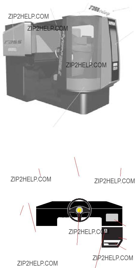
19. DESIGN RELATED PARTS
For the Warning Display stickers, refer to Section 1.
COVER
 CONT PANEL
20. PARTS LIST
www.seuservice.com74


1 TOP ASSY FRI DX
(
NOTE
AC 110V AREA
AC 220V AREA
AC 240V AREA
AC 120V AREA
3

NOTE) M8 BOLT FASTENING TORQUE TO BE:178kgf???cm
77www.seuservice.com


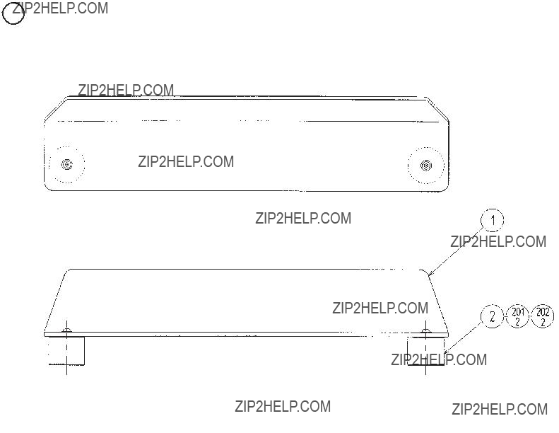
4 ASSY BILLBOARD
NOTE) M8 TAMPER FASTENING TORQUE TO BE: 30kgf???cm
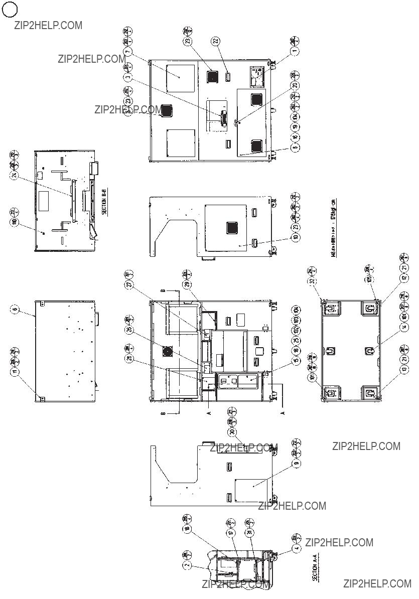
M8 BOLT FASTENING TORQUE TO BE:178kgf???cm


7 SW UNIT

8 FAN MOTOR UNIT
Connector

9 METER UNIT S

9 METER UNIT T
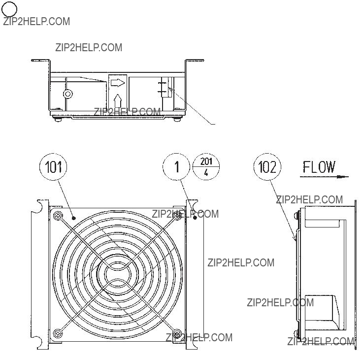
10 FAN UNIT
Connector
ITEM NO. PART NO. DESCRIPTIONNOTE
1

11 ASSY WIRE FRONT CABI AC
ASSY WIRE FRONT CABI AC is comprised of the following wire harnesses. An ASSY DRG. is unavailable.
12 ASSY WIRE FRONT CABI DC
ASSY WIRE FRONT CABI DC is comprised of the following wire harnesses. An ASSY DRG. is unavailable.
13 ASSY WIRE EARTH
ASSY WIRE EARTH is comprised of the following wire harnesses.
An ASSY DRG. is unavailable.
14 ASSY MONITOR CENTER

Details of PART A


Details of PART A


TORQUE


SCREW FASTENING TORQUE TO BE

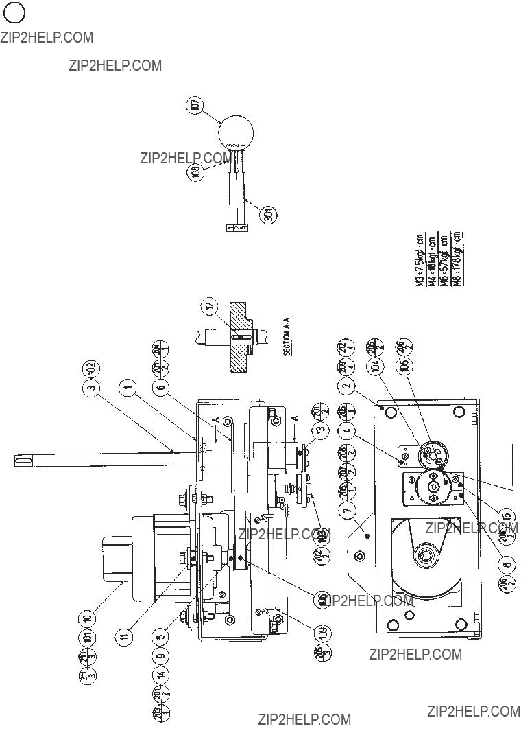
SCREW FASTENING TORQUE TO BE
Apply greasing

20 PEDAL UNIT
SCREW FASTENING TORQUE TO BE
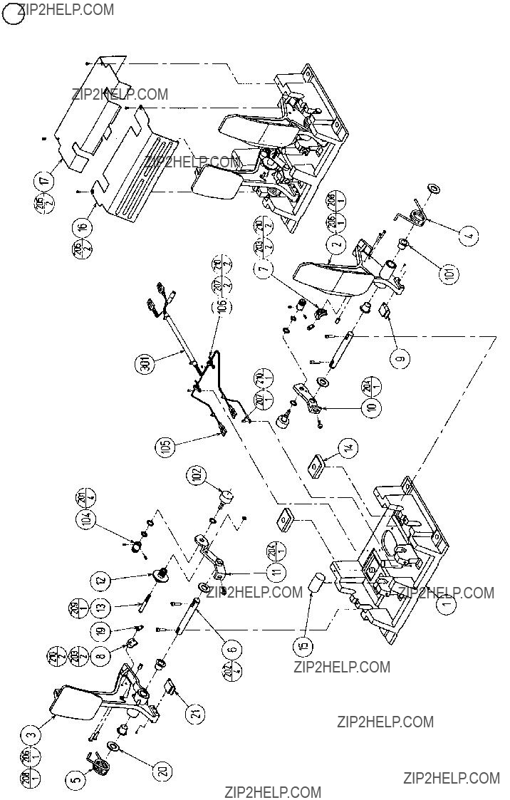

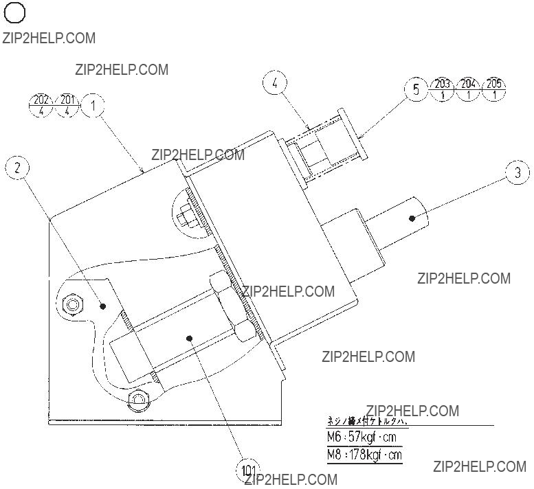
22 ABSORBER UNIT
SCREW FASTENING TORQUE TO BE

Apply greasing to gear mesh portions and spring portions.


25 ASSY WIRE REAR
ASSY WIRE REAR is comprised of the following wire harnesses.
An ASSY DRG. is unavailable.


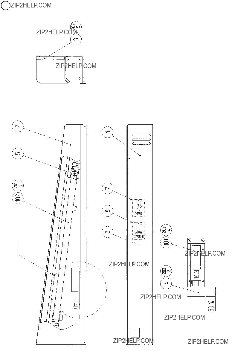
A portion
Details of PART A


A portion
Details of PART A

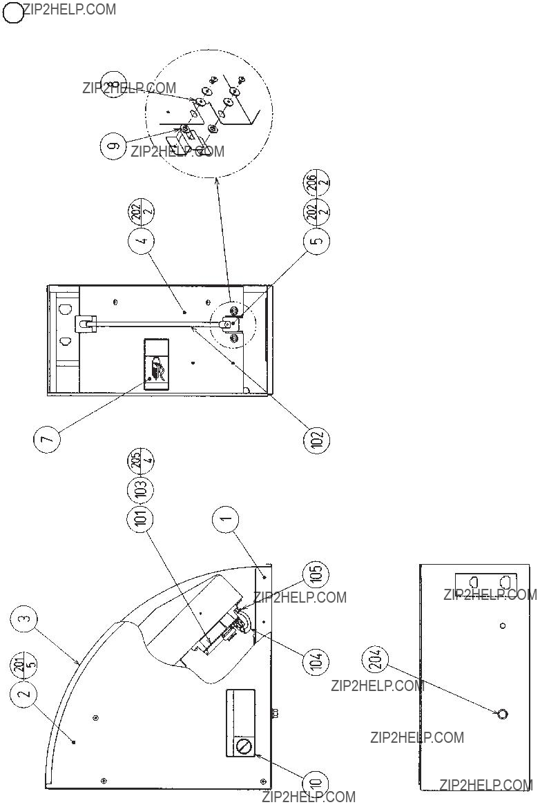


125www.seuservice.com

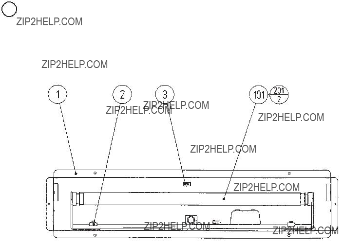
32 ASSY TOP LIGHT
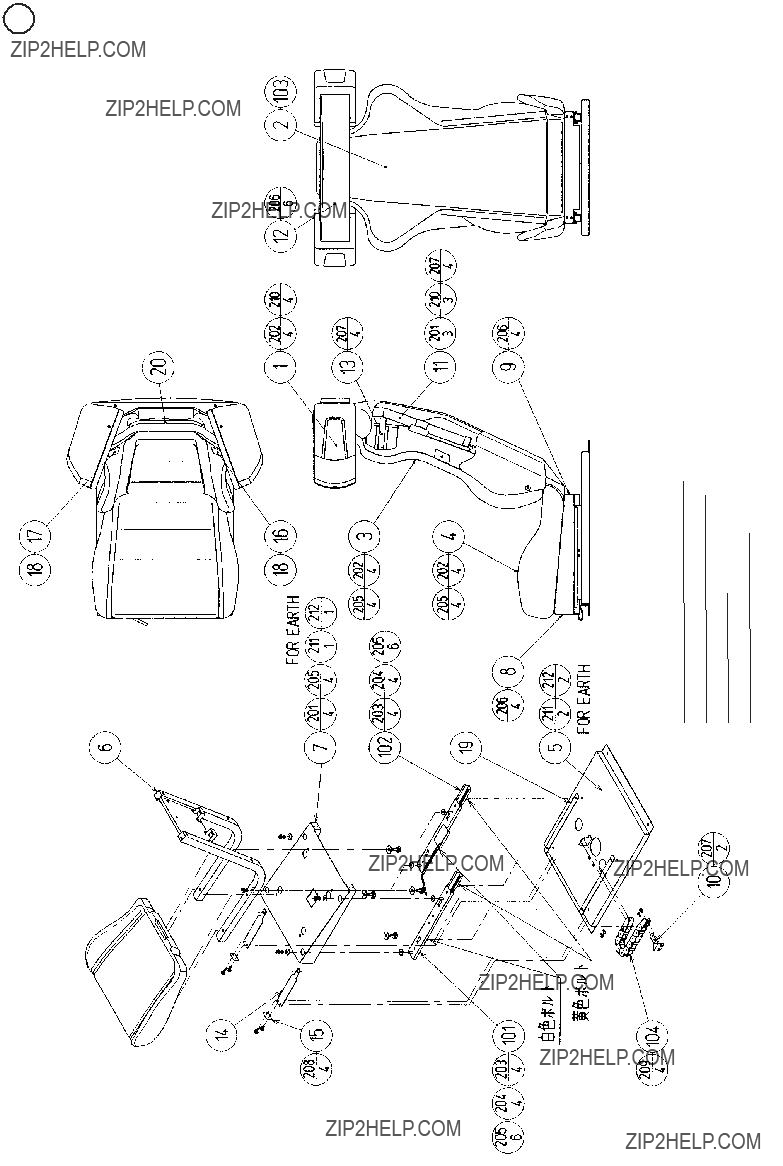


34 SOUND UNIT

SEE A (Where ??A is removed.)


36 ASSY EFECT SW


Note) 1.
2.Make sure that there is no wiring, etc. in the slash mark portions.


40 ASSY I/O BASE DX
NOTE) Make sure that there is no wiring, etc.
in the slash mark portions.
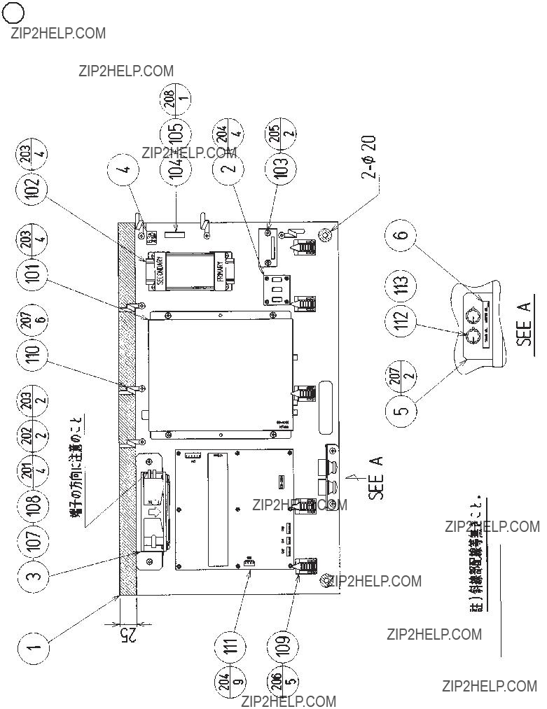


42 ASSY SERVO DRV BASE DX
21. WIRE COLOR CODE TABLE
THE WIRE COLOR CODE is as follow:
APINK
BSKY BLUE
CBROWN
DPURPLE
ELIGHT GREEN
Wires other than those of any of the above 5 single colors will be displayed by 2 alphanumeric characters.
1RED
2BLUE
3YELLOW
4GREEN
5WHITE
7ORANGE
8BLACK
9GRAY
If the
Note 1: If the
RED WHITE
Note 2: The character following the wire color code indicates the size of the wire.
U:AWG16, UL1015
K:AWG18, UL1015
L:AWG20, UL1007

Warranty
Your new Sega Product is covered for a period of 90 days from the date of shipment. This certifies that the Printed Circuit Boards, Power Supplies and Monitor are to be free of defects in workman- ship or materials under normal operating conditions. This also certifies that all Interactive Control Assemblies are to be free from defects in workmanship and materials under normal operating condi- tions. No other product in this machine is hereby covered.
Sellers sole liability in the event a warranted part described above fails shall be, at its option, to replace or repair the defective part during the warranty period. For Warranty claims, contact your Sega Distributor.
Should the Seller determine, by inspection that the product was caused by Accident, Misuse, Ne- glect, Alteration, Improper Repair, Installation or Testing, the warranty offered will be null and void.
Under no circumstances is the Seller responsible for any loss of profits, loss of use, or other dam- ages.
This shall be the exclusive written Warranty of the original purchaser expressed in lieu of all other warranties expressed or implied. Under no circumstance shall it extend beyond the period of time listed above.