Use & Care Guide
Model No.
153.332620 40 Gallon Tall
153.332640 50 Gallon Tall
Kenmore Elite??
Gas Water Heater
For potable water heating only.
Not suitable for space heating.
Not for use in mobile homes.
INSTALLER: Affix these instructions to or near the water heater.
OWNER: Retain these instructions for future reference.
FOR YOUR SAFETY: An odorant is added to the gas used by this water heater.
ADVERTENCIA
Si no puede leer o entender el ingl??s y necesita el manual de instrucciones en espa??ol, puede solicitarlo al 1-800-821-2017. NO
TRATE DE INSTALAR U OPERAR ESTE CALENTADOR DE AGUA SI NO ENTIENDE LAS INSTRUCCIONES. No hacer caso de esta advertencia podr??a originar lesiones graves o mortales.
P/N 317997-000 (0810)
Sears Brands Management Corporation,
Hoffman Estates, IL 60179 U.S.A.
www. kenmore.com
www.sears.com
SAFE INSTALLATION, USE AND SERVICE
Your safety and the safety of others is extremely important in the installation, use and servicing of this water heater.
Many safety-related messages and instructions have been provided in this manual and on your own water heater to warn you and others of a potential injury hazard. Read and obey all safety messages and instructions throughout this manual. It is very important that the meaning of each safety message is understood by you and others who install, use or service this water heater.
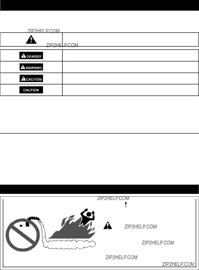
This is the safety alert symbol. It is used to alert you to potential personal injury hazards.
Obey all safety messages that follow this symbol to avoid possible injury or death.
DANGER indicates an imminently hazardous situation which, if not avoided, will result in death or injury.
WARNING indicates a potentially hazardous situation which, if not avoided, could result in death or injury.
CAUTION indicates a potentially hazardous situation which, if not avoided, may result in minor or moderate injury.
CAUTION used without the safety alert symbol indicates a potentially hazardous situation which, if not avoided, could result in property damage.
All safety messages will generally tell you about the type of hazard, what can happen if you do not follow the safety message and how to avoid the risk of injury.
The California Safe Drinking Water and Toxic Enforcement Act requires the Governor of California to publish a list of substances known to the State of California to cause cancer, birth defects, or other reproductive harm, and requires businesses to warn of potential exposure to such substances. WARNING: This product contains a chemical known to the State of California to cause cancer, birth defects, or other reproductive harm. This appliance can cause low-level exposure to some of the substances included in the Act.
IMPORTANT DEFINITIONS
???Quali???ed Technician: A quali???ed technician must have ability equivalent to a licensed tradesman in the ???elds of plumbing, air supply, venting, and gas supply, including a thorough understanding of the requirements of the National Fuel Gas Code as it relates to the installation of gas ???red water heaters. The quali???ed technician must also be familiar with the design features and use of ???ammable vapor ignition resistant water heaters, and have a thorough understanding of this instruction manual.
???Service Agency: A service agency also must have ability equivalent to a licensed tradesman in the ???elds of plumbing, air supply, venting and gas supply, including a thorough understanding of the requirements of the National Fuel Gas Code as it relates to the installation of gas ???red water heaters. The service agency must also have a thorough understanding of this instruction manual, and be able to perform repairs strictly in accordance with the service guidelines provided by the manufacturer.
???Gas Supplier: The natural gas or propane utility or service who supplies gas for utilization by the gas burning appliances within this application. The gas supplier typically has responsibility for the inspection and code approval of gas piping up to and including the natural gas meter or propane storage tank of a building. Many gas suppliers also offer service and inspection of appliances within the building.
SAFETY PRECAUTIONS
Read and follow water heater warnings and instructions.
?? Sears Brands Management Corporation
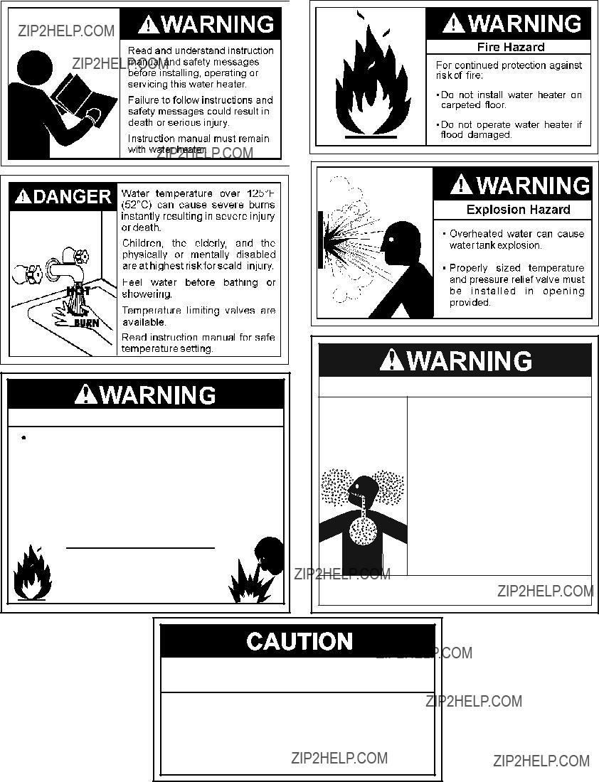
Fire or Explosion Hazard
Do not store or use gasoline or other flammable vapors and liquids in the vicinity of this or any other appliance.
 Avoid all ignition sources if you smell Natural or LP gas.
 Do not expose water heater control to excessive gas pressure.
 Use only gas shown on rating plate.
 Maintain required clearances to combustibles.
 Keep ignition sources away from faucets after extended period of non-use.
Read instruction manual before installing, using or servicing water heater.
Breathing Hazard - Carbon Monoxide Gas
 Install vent system in accordance with codes.
 Do not operate water heater if flood damaged
 Heater should not be installed for High Altitude operation above 10,100 feet (3,078 m).
 Do not operate if soot buildup.
 Do not obstruct water heater air intake with insulating jacket.
 Do not place chemical vapor emitting products near water heater.
 Gas and carbon monoxide detectors are available.
Breathing carbon monoxide can cause brain damage or death. Always read and understand instruction manual.
Improper installation and use may result in property damage.
 Do not operate water heater if flood damaged.
 Install in location with drainage.
 Fill tank with water before operation.
  Be alert for thermal expansion.
Refer to instruction manual for installation and service.
PRODUCT WARRANTY
12 - YEAR LIMITED WARRANTY ON WATER HEATER
For twelve years from the date of purchase, if this water heater is installed and operated in a single-family home in accordance with the owner???s manual instructions and all local applicable plumbing codes, Sears will:
1.Supply free water heater parts for those that are defective in material or workmanship.
2.Supply a free water heater for one that develops a leak.
For the second through twelfth year from the purchase date, you must pay the labor cost for installation of parts or water heater.
For commercial, institutional, industrial or residential use by two or more families, the above limited warranty is only for two years. During the second year you must pay the labor cost for parts or water heater installation.
If governmental regulations prohibit Sears from furnishing a comparable model replacement water heater under this warranty, Sears will furnish a new water heater of comparable output as permitted by such governmental regulations; however, the Owner will be charged for the additional cost associated with the changes made to comply with such governmental regulations.
Replacements furnished under this warranty do not carry a new warranty; and are only covered by the unexpired portion of the original warranty.
1 - YEAR EXCLUSIVE KENMORE LABOR WARRANTY
For the ???rst year from the date of purchase, Sears will, free of charge, supply and install new water heater parts for defective ones or a new water heater for one that develops a leak.
WARRANTY SERVICE
To obtain warranty service, call 1-800-4-MY-HOME?? (1-800-469-4663).
This warranty applies only while this product is in use in the United States.
This warranty gives you speci???c legal rights, and you may also have other rights which vary from state to state.
SEARS BRANDS MANAGEMENT CORPORATION, Hoffman Estates, IL 60179
The price of your water heater does not include a free checkup service call. On water heater installations arranged by Sears, Sears
warrants the installation.
A charge will be made on service calls due to poor or incomplete installation. These include:
Master Protection Agreements
Congratulations on making a smart purchase. Your new Kenmore?? product is designed and manufactured for years of dependable operation. But like all products, it may require preventive maintenance or repair from time to time. That???s when having a Master Protection Agreement can save you money and aggravation.
The Master Protection Agreement also helps extend the life of your new product. Here???s what the Agreement* includes:
???Parts and labor needed to help keep products operating properly under normal use, not just defects. Our coverage goes well beyond the product warranty. No deductibles, no functional failure excluded from coverage??? real protection.
???Expert service by a force of more than 10,000 authorized Sears service technicians, which means someone you can trust will be working on your product.
???Unlimited service calls and nationwide service, as often as you want us, whenever you want us.
??????No-lemon??? guarantee ??? replacement of your covered product if four or more product failures occur within twelve months.
???Product replacement if your covered product can???t be fixed.
???Annual Preventive Maintenance Check at your request ??? no extra charge.
???Fast help by phone ??? we call it Rapid Resolution ??? phone support from a Sears representative on all products. Think of us as a ???talking owner???s manual.???
???Power surge protection against electrical damage due to power fluctuations.
???$250 Food Loss Protection annually for any food spoilage
???Rental reimbursement if repair of your covered product takes longer than promised.
???10% discount off the regular price of any non-covered repair service and related installed parts.
Once you purchase the Agreement, a simple phone call is all that it takes for you to schedule service. You can call anytime day or night, or schedule a service appointment online.
The Master Protection Agreement is a risk free purchase. If you cancel for any reason during the product warranty period, we will provide a full refund. Or, a prorated refund anytime after the product warranty period expires. Purchase your Master Protection Agreement today!
Some limitations and exclusions apply. For prices and additional information in the U.S.A. call 1-800-827-6655.
* Coverage in Canada varies on some items. For full details, call Sears Canada at 1-800-361-6665.
Sears Installation Service
For Sears professional installation of home appliances, garage door openers, water heaters, and other major home items, in the U.S.A. or Canada call 1-800-4-MY-HOME??.
CUSTOMER RESPONSIBILITIES
Thank You for purchasing a Kenmore water heater. Properly installed and maintained, it should give you years of trouble free service. If you should decide that you want the new water heater professionally installed by Sears call 1-800-4-MY-HOME??. They will arrange for prompt, quality installation by Sears authorized contractors.
Abbreviations Found In This Instruction Manual:
???CSA - Canadian Standards Association
???ANSI - American National Standards Institute
???NFPA - National Fire Protection Association
???ASME - American Society of Mechanical Engineers
???GAMA - Gas Appliance Manufacturers Association
Important Information About This Water Heater:
This gas water heater was manufactured to voluntary safety standards to reduce the likelihood of a ???ammable vapor ignition incident. New technology used in meeting these standards makes this product more sensitive to installation errors or improper installation environments. Please review the Installation Checklist section and make any required installation upgrades or changes.
This manual contains instructions for the installation, operation, and maintenance of the gas-???red water heater. It also contains warnings through out the manual that you must read and be aware of. All warnings and all instructions are essential to the proper operation of the water heater and your safety. Since we cannot put everything on the ???rst few pages, READ THE ENTIRE MANUAL
BEFORE ATTEMPTING TO INSTALL OR OPERATE THE WATER
HEATER.
???The installation must conform with these instructions and the local code authority having jurisdiction. In the absence of local codes, installations shall comply with the following:
In the United States: The National Fuel Gas Code ANSI Z223.1/ NFPA 54. This publication is available from the Canadian Standards Association, 8501 East Pleasant Valley Rd, Cleveland Ohio 44131, or The National Fire Protection Association, 1 Batterymarch Park, Quincy, MA 02269.
???If after reading this manual you have any questions or do not understand any portion of the instructions, call the Sears Service Center.
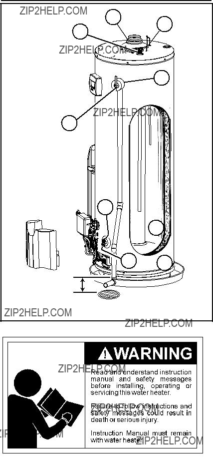
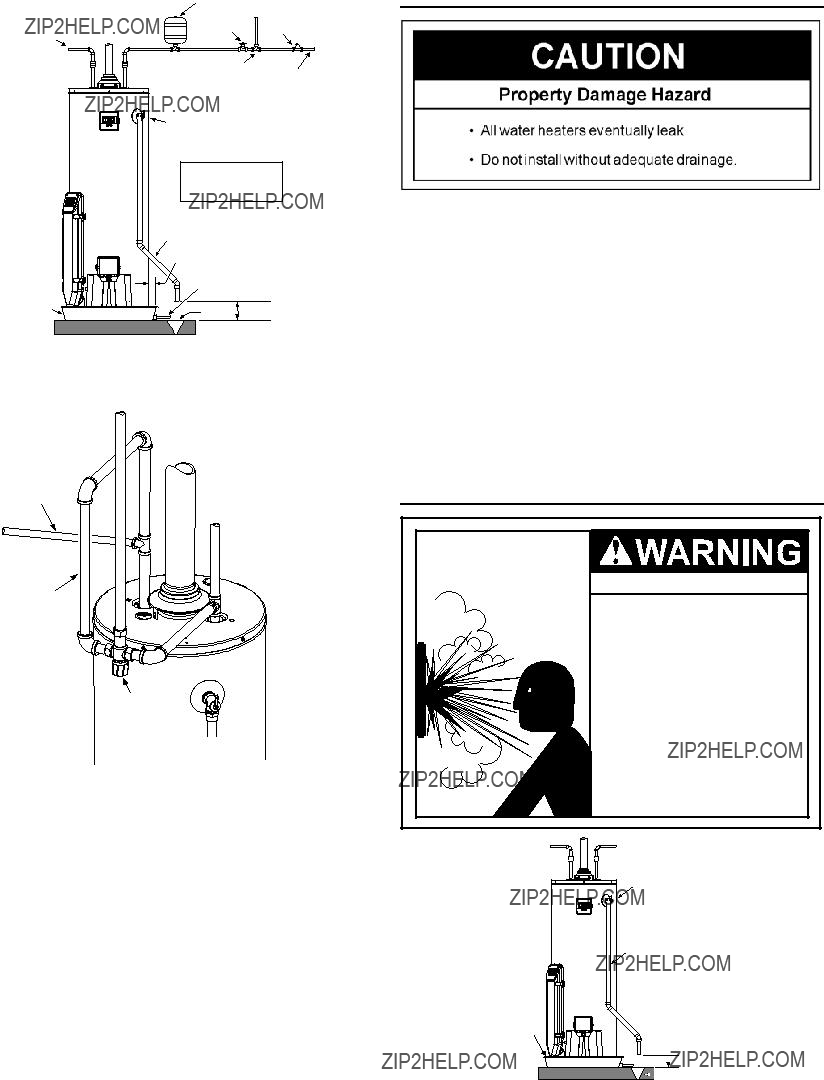
???Carefully plan the place where you are going to put the water heater. Correct combustion, vent action, and vent pipe installation are very important in preventing death from possible carbon monoxide poisoning and ???res. See Figure 1.
???Examine the location to ensure the water heater complies with the Installation Instructions section in this manual.
???For California installation, this water heater must be braced, anchored, or strapped to avoid falling or moving during an earthquake. See instructions for correct installation procedures. Instructions may be obtained from California???s Of???ce of the State Architect, 1102 Q Street, Suite 5100, Sacramento, CA 95811. Instructions can also be downloaded to your computer at www.dsa.dgs.ca.gov/Pubs.
???Massachusetts Code requires this water heater to be installed in accordance with Massachusetts 248-CMR 2.00: State Plumbing Code and 248-CMR 5.00.
???Complies with 40 Ng/J NOx requirements of Texas and most California AQM Districts.
 WARNING
Excessive Weight Hazard
Use two or more people to move and install the water heater. Failure to do so can result in injury (including back injury).
IMPORTANT: Do not remove any permanent instructions, labels, or the data label from either the outside of the water heater or on the inside of water heater panels.
???Remove exterior packaging and place installation components aside.
???Inspect all parts for damage prior to installation and start-up.
???Completely read all instructions before attempting to assemble and install this product.
???After installation, dispose of/recycle all packaging materials.
MATERIALS AND BASIC TOOLS NEEDED
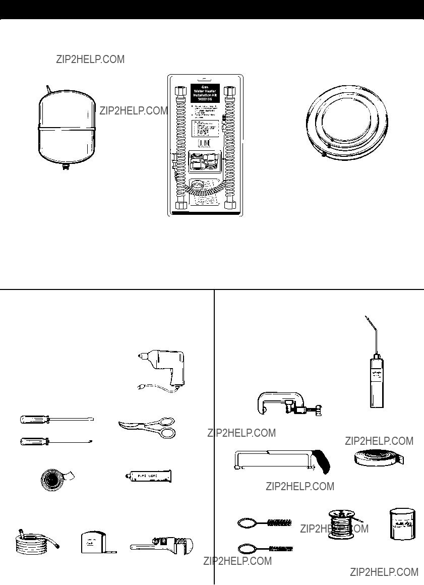
MATERIALS NEEDED
To simplify the installation Sears has available the installation parts shown below. You may or may not need all of these materials, depending on your type of installation.
EXPANSION TANKS FOR
THERMAL EXPANSION
CONDITIONS AVAILABLE
IN 2 GALLONS (7.6 LITERS) AND
5 GALLONS (18.9 LITERS)
CAPACITY THROUGH
LOCAL SEARS STORE
OR SERVICE CENTER.
WAT E R H E AT E R I N S TA L L AT I O N K I T
WITH FLEXIBLE CONNECTORS FOR 3/4??? (19.05 mm) COPPER PLUMBING AND FLEXIBLE
GAS CONNECTOR WITH FITTINGS.
METAL DRAIN PANS AVAILABLE IN 20??? (508 mm) DIAMETER
FOR WATER HEATERS HAVING A DIAMETER 18??? (457 mm) OR LESS, 24??? (610mm) DIAMETER
FOR WATER HEATERS HAVING A DIAMETER 22??? (559 mm) OR LESS AND AVAILABLE IN 28??? (711 mm)
DIAMETER FOR WATER HEATERS HAVING A DIAMETER 26??? (660 mm)
OR LESS.
BASIC TOOLS
You may or may not need all these tools, depending on your type of installation. These tools can be purchased at your local Sears Store.
ADDITIONAL TOOLS NEEDED
WHEN SWEAT SOLDERING
???Pipe Wrenches (2) 14??? (356 mm)
???Screwdriver
???Tin Snips
???6??? (1.82 m) Tape or Folding Ruler
???Garden Hose
???Drill
???Pipe Dope or Te???on Tape
SLOT-HEAD SCREWDRIVER
PHILLIPS SCREWDRIVER
ROLL OF TEFLON
TAPE (USE ONLY ON
WATER CONNECTIONS)
DRILL
TIN SNIPS
PIPE DOPE
(SQUEEZE TUBE)
USE FOR WATER AND GAS
CONNECTIONS
TYPICAL INSTALLATION
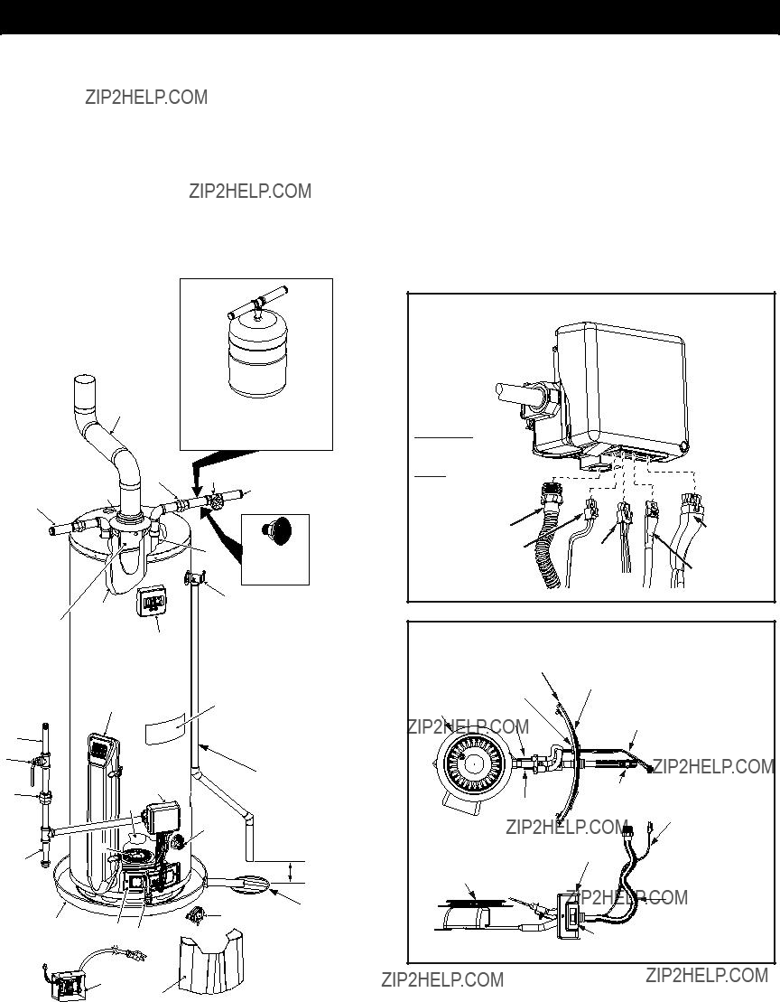
GET TO KNOW YOUR WATER HEATER - GAS MODELS
*INSTALL IN ACCORDANCE
WITH LOCAL CODES.
*DRIP LEG AS REQUIRED
BY LOCAL CODES.
* ALL PIPING MATERIALS
TO BE SUPPLIED BY
CUSTOMERS.
(S) GAS CONTROL VALVE/THERMOSTAT
TO VENT TERMINATION
ON ROOF
Y
K
IMPORTANT: DO NOT USE AN EXTENSION CORD TO CONNECT
THE WATER HEATER TO AN ELECTRICAL OUTLET.
FIGURE 1.
instructions (See Water Temperature Regulation section).
Gas Supply and Piping
??? Gas type is the same as that listed on the water heater rating plate.
??? Gas line equipped with shut-off valve, union, and drip leg.
??? Use pipe joint compound or teflon tape marked as being resistant to the action of petroleum gases.
??? Adequate pipe size and approved pipe material.
??? An approved noncorrosive leak detection solution used to check all connections and fittings for possible gas leaks.
Correct any leak found.
Electrical Supply
??? Water heater to be located as close as possible to a 120VAC outlet (extension cord is not allowed).
??? Electrical supply installed according to all local and state codes or, in the absence of local and state codes, the
???National Electrical Code???, ANSI/NFPS 70 current edition.
All piping properly installed and free of leaks. Heater completely filled with water.
Closed system pressure build-up devices installed.
Mixing valve (when applicable) installed per manufacturer???s
???
???
???
???
Temperature and pressure relief valve properly installed with a discharge line run to an open drain and protected from freezing.
???
Water System Piping
Recheck for sufficient combustion air supply.
???
codes or, in the absence of local and state codes, the ???National Fuel Gas Code???, ANSI Z223.1(NFPA 54)-current edition.
??? Flue baffle properly positioned in the flue tube.
??? Check the vent system for restrictions/obstructions and check the vent termination height. Refer to the ???Combustion Air and Ventilation??? section of this water heater manual for specific requirements.
Vent pipe system installed according to all local and state
???
Vent connector made of approved material and sized correctly.
???
Draft hood properly installed.
Vent connectors securely fastened with screws and supported properly to maintain six inch clearance.
???
???
Vent Pipe System
Check for proper drafting at the water heater draft hood. Refer to the ???Checking the Draft??? section of this manual for the test procedure. If the procedure shows insufficient draft is present, please check the following.
IMPORTANT INFORMATION ABOUT THIS WATER HEATER
This gas water heater was manufactured to voluntary safety standards to reduce the likelihood of a flammable vapor ignition incident. The new technology used in meeting these standards makes this product more sensitive to installation errors. Please review the following checklist and make any required installation upgrades or changes.
Questions? Contact Sears at (1-800-469-4663).
Installation Checklist
Water Heater Location
Water heater location is important and can affect system performance. Please check the following:
Installation area free of corrosive elements and flammable materials.
Centrally located with the water piping system (For new installations). Located as close to the gas piping, vent pipe system and 120VAC outlet as possible.
Located indoors and in a vertical position. Protected from freezing temperatures.
Proper clearances from combustible surfaces maintained and not installed directly on a carpeted floor.
Provisions made to protect the area from water damage. Metal drain pan installed and piped to an adequate drain.
Sufficient room to service the water heater. See Clearances and Accessibility section of this manual.
Water heater not located near an air moving device.
Is the installed environment dirty (excessive amounts of lint, dirt, dust, etc.)? If so, the air intake chamber louvers located on the side of the water heater will need to be cleaned periodically. Refer to the maintenance section of your water heater???s manual for information on cleaning the ???Air Intake Chamber Screen???.
Combustion Air Supply and Ventilation
Check for sufficient combustion air supply. Insufficient air for the combustion of gas will result in a inferior burner flame ???yellow- lazy???, thereby allowing smoking and carbon formation (sooting) to build up in the combustion chamber.
Is the water heater installed in a closet or other small, enclosed space? If so:
???Are there openings for make-up air to enter and exit the room/area?
???Are the openings of sufficient size? Remember, if there are other gas-fired or air-consuming appliances in the same room, you need more make-up air. Refer to the Location Requirements section of this water heater manual for specific requirements.
Fresh air not taken from areas that contain negative pressure producing devices such as exhaust fans, dryers, fireplaces, etc.
???Is there a furnace/air handler in the same room space as the water heater? If so, has a return air duct system been attached that exits the room? If so, check for leaks on the air duct system. If no air duct system is present, correct immediately by contacting a local Heating, Ventilation, Air- Conditioning & Refrigeration (HVAC-R) authorized service provider.
???Fresh air supply free of corrosive elements and flammable vapors.
???Ductwork is the same cross-sectional area as the openings.
INSTALLATION INSTRUCTIONS
Removing the Old Water Heater
6 1 


MANUAL GAS
SHUT-OFF VALVE
GROUND


JOINT
UNION
CHECK WITH
LOCAL UTILITY
5 
 2
2
 DISCHARGE PIPE
(DO NOT CAP
OR PLUG)
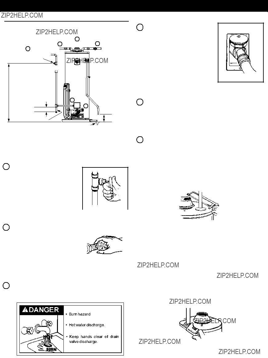
4.Attach a hose to the water heater drain valve and put the other end in a ???oor drain or outdoors. (See Figures 2 and 5.) Open the water heater drain valve.
FIGURE 5.
FOR MINIMUM HEIGHT
DRIP LEG
FIGURE 2.
1.Turn ???OFF??? the gas supply to the water heater.
If the main gas line shutoff valve serving all gas appliances is used, also shut ???OFF??? the gas at each appliance. Leave all gas appliances
and 4.
3.Check again to make sure the gas supply is ???OFF??? to the water heater. Then disconnect the gas supply connection from the gas control valve.
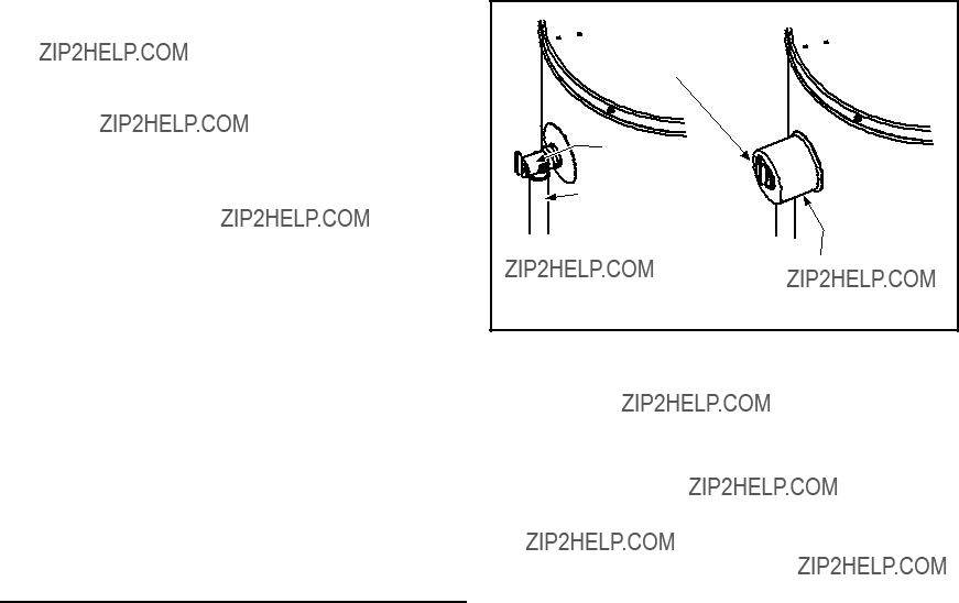
6.If you have copper piping to the water heater, the two copper water pipes can be cut with a hacksaw approximately four inches away from where they connect to the water heater. See Figure 6. This will avoid cutting off pipes too short. Additional cuts can be made later if necessary. Disconnect the temperature-pressure relief valve drain line. When the water heater is drained, disconnect the hose from the drain valve. Close the drain valve. The water heater is now completely disconnected and ready to be removed.
FIGURE 6.
If you have galvanized pipes to the water heater, loosen the two galvanized pipes with a pipe wrench at the union in each line. Also disconnect the piping remaining to the water heater. See Figure 7. These pieces should be saved since they may be needed when reconnecting the new water heater. Disconnect the temperature-pressure relief valve drain line. When the water heater is drained, disconnect the hose from the drain valve. Close the drain valve. The water heater is now completely disconnected and ready to be removed. Mineral buildup or sediment may have accumulated in the old water heater. This causes the water heater to be much heavier than normal and this residue, if spilled out, could cause staining.
COMBUSTION AIR & VENTILATION
 WARNING
Carbon Monoxide Warning
Water heater must be vented to outdoors.
Vent must be installed by a qualified technician using the installation instructions.
Examples of a qualified technican include: gas technicians, authorized gas company personel, and authorized service persons.
Failure to so do can result in death or carbon monoxide poisoning.
IMPORTANT: Air for combustion and ventilation must not come from a corrosive atmosphere. Any failure due to corrosive elements in the atmosphere is excluded from warranty coverage.
The following types of installation (not limited to the following) will require outdoor air for combustion due to chemical exposure and may reduce but not eliminate the presence of corrosive chemicals in the air:
???beauty shops
???photo processing labs
???buildings with indoor pools
???water heaters installed in laundry, hobby, or craft rooms
???water heaters installed near chemical storage areas
Combustion air must be free of acid-forming chemicals such as sulfur, fluorine, and chlorine. These elements are found in aerosol sprays, detergents, bleaches, cleaning solvents, air fresheners, paint, and varnish removers, refrigerants, and many other commercial and household products. When burned, vapors from these products form highly corrosive acid compounds. These products should not be stored or used near the water heater or air inlet.
Combustion and ventilation air requirements are determined by the location of the water heater. The water heater may be located in either an open (unconfined) area or in a confined area or small enclosure such as a closet or small room. Confined spaces are areas with less than 50 cubic feet for each 1,000 BTUH of the total input for all gas-using appliances.
Unconfined Space
A water heater in an unconfined space uses indoor air for combustion and requires at least 50 cubic feet for each 1,000 BTUH of the total input for all gas appliances. The table below shows a few examples of the minimum square footage (area) required for various BTUH inputs.
TABLE 3
IMPORTANT:
???The area must be open and be able to provide the proper air requirements to the water heater. Areas that are being used for storage or contain large objects may not be suitable for water heater installation.
???Water heaters installed in open spaces in buildings with un- usually tight construction may still require outdoor air to func- tion properly. In this situation, outside air openings should be sized the same as for a confined space.
???Modern home construction usually requires supplying out- side air into the water heater area.
Confined Space
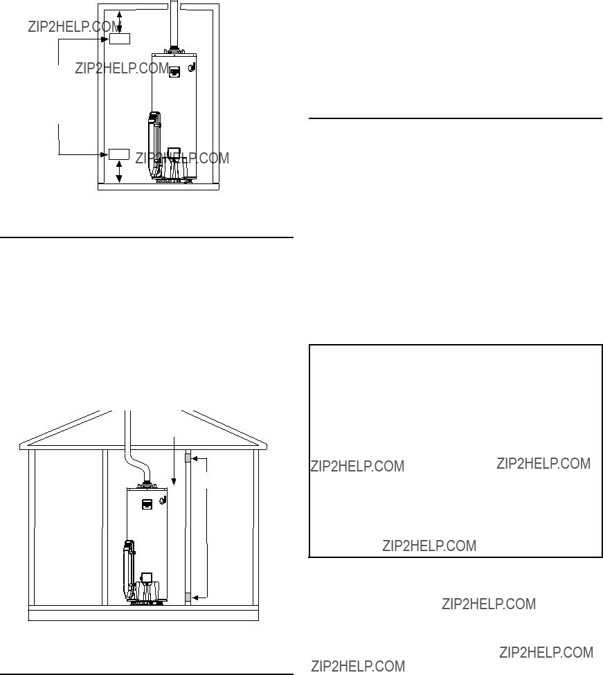
For the correct and proper operation of this water heater, ample air must be supplied for the combustion, ventilation, and dilution of flue gases. Small enclosures and confined areas must have two permanent openings so that sufficient fresh air can be drawn from outside of the enclosure. One opening shall be within 12 inches of the top and one within 12 inches of the bottom of the enclosure as shown in Figure 13.
The size of each opening (free area) is determined by the total BTUH input of all gas utilization equipment (i.e., water heaters, furnaces, clothes dryers, etc.) and the method by which the air is provided. The BTUH input can be found on the water heater rating plate. Additional air can be provided by two methods:
1.All air from inside the building.
2.All air from outdoors.
For protection against excessive pressures and temperatures, a temperature and pressure relief valve must be installed in the opening marked ???T & P RELIEF VALVE??? (see Figure 25). This valve must be design certified by a nationally recognized testing laboratory that maintains periodic inspection of the production of listed equipment or materials as meeting the requirements for Relief Valves for Hot Water Supply Systems, ANSI Z21.22. The function of the temperature and pressure relief valve is to discharge water in large quantities in the event of excessive temperature or pressure developing in the water heater. The valve???s relief pressure must not exceed the working pressure of the water heater as stated on the rating plate.
IMPORTANT: Only a new temperature and pressure relief valve should be used with your water heater. Do not use an old or existing valve as it may be damaged or not adequate for the working pressure of the new water heater. Do not place any valve between the relief valve and the tank.
The Temperature & Pressure Relief Valve:
???Must not be in contact with any electrical part.
???Must be connected to an adequate discharge line.
???Must not be rated higher than the working pressure shown on the rating plate of the water heater.
The Discharge Line:
???Must not be smaller than the pipe size of the relief valve or have any reducing coupling installed in the discharge line.
???Must not be capped, blocked, plugged or contain any valve between the relief valve and the end of the discharge line.
???Must terminate a maximum of six inches above a floor drain or external to the building. In cold climates, it is recommend- ed that the discharge pipe be terminated at an adequate drain inside the building.
???Must be capable of withstanding 250??F (121??C) without dis- tortion.
???Must be installed to allow complete drainage of both the valve and discharge line.
4.Locate the hot water (outlet) & cold water (inlet) pipes to the water heater.
5.Locate the slit running the length of a section of pipe insulation.
6.Spread the slit open and slip the insulation over the cold water (inlet) pipe. Apply gentle pressure along the length of the insulation to ensure it is fully seated around the pipe. Also ensure that the base of insulation is flush with the water heater. Once seated, secure the insulation with duct tape, electrical tape, or equivalent.
7.Repeat steps 5 through 6 for the hot water (outlet) pipe.
8.Add additional sections of pipe insulation as needed.
T&P Relief Valve and Pipe Insulation
1.Locate the temperature and relief valve on the water heater (also known as a T&P Relief Valve, Figure 26).
2.Locate the slit running the length of the insulation.
3Spread this slit open and slip it up under the T&P Relief Valve. See Figure 26. Apply gentle pressure to the insulation to ensure it is fully seated on the T&P Relief Valve. Once sealed secure the insulation with a section of duct tape, electrical tape, or equivalent.
IMPORTANT: The insulation or tape must not block the discharge opening or hinder access to the manual relief lever. Ensure a discharge pipe is installed into the T&P valve discharge opening per the instructions manual.
OPERATING YOUR WATER HEATER
Operating Instructions
Read and understand these directions thoroughly before attempting to operate the water heater. Make sure the view port is not missing or damaged (See Figure 36). Make sure the tank is completely filled with water before operating the water heater. The gas control valve/thermostat has a ???On/Off Switch??? and needs to be turned on before water heater is operational. Check the label on the front of heater near the gas control valve/ thermostat for the correct gas. Do not use this water heater with any gas other than the one listed on the label. If you have any questions or doubts, consult your gas supplier or gas utility company.
 WARNING
Explosion Hazard
Replace view port if glass is missing or damaged.
Failure to do so can result in death, explosion or fire.
FOR YOUR SAFETY READ BEFORE OPERATING
OPERATING INSTRUCTIONS
ON
ON/OFF
SWITCH
"GAS CONTROL"
1.STOP! Read the safety information
above on the label.
2.Turn on all electrical power to the appliance.
3.Set the ON/OFF switch on the gas control to the "ON" position.
4.Set the Electronic Display to the lowest setting by first pressing the COOLER and HOTTER  buttons together and holding for 1 second. Then press the COOLER button to the lowest setting.
5.Set the ON/OFF switch on the gas control to the "OFF" position.
6.This appliance is equipped with a device which automatically lights the burner.
DO NOT TRY TO LIGHT THE BURNER BY HAND.
the safety information above on this label. If you don't smell gas, go to the next step.
"ELECTRONIC DISPLAY"
8.Set the ON/OFF switch on the gas control to the "ON" postition.
9.Set the Electronic Display to the desired setting by first pressing the COOLER  and HOTTER
  but- tons together and holding for 1 second. Then press the HOTTER
  button until the desired setting is reached.
DANGER: Hotter water increases the risk scald injury. Consult the instruction manual before changing temperature.
10.If the appliance will not operate, follow the instruc- tions "TO TURN OFF GAS TO APPLIANCE" and call your technician or gas supplier.
WARNING: TURN OFF ALL
ELECTRIC POWER BEFORE SERVICING.
TO TURN OFF GAS TO APPLIANCE
1. Set the Electronic Display to the lowest setting by first pressing the COOLER and HOTTER but- tons together and holding for 1 second. Then press the COOLER  button to the lowest setting.
2.Set the ON/OFF switch on the gas control to the "OFF" postition.
3.Turn off all electrical power to the appliance if service is to be performed.
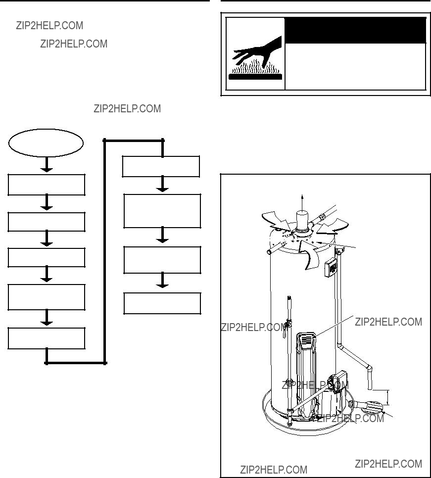
Water Heater Operation
Figure 29 below shows the water heater???s sequence of operation when a call for heat is initiated. The ignition control module will attempt to light the burner three times. If the ignition control does not detect ignition it will enter lockout mode, indicated by display flashing status code (see status code 3 page 38 and/or status code 8 page 39).
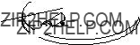
Checking the Draft
 WARNING
Burn Hazard
Do not touch vent.
Doing so can result in burns.
After successfully lighting the water heater, allow the unit to operate for 15 minutes and check the draft hood relief opening for proper draft (Figure 30). Make sure all other appliances in the area are operating and all doors/windows are closed when
Call for heat indicated by flashing of display screen status codes.
Gas valve/thermostat will open for 4 second trial for ignition and fan will turn on.
performing the draft test. Pass a match flame or smoke around the relief opening of the draft hood. A steady flame or smoke drawn into the opening indicates proper draft.
Gas valve/thermostat will do a relay check (relay clicks will be heard).
Display will show temperature set point during call for heat.
Draft Blower is energized.
System will verify pressure switch operation and start a 5 second pre-purge, then air intake fan will turn off.
Ignitor will start a 12 second warm up period. ???IGN??? will show on display.
Main burner flame is detected by flame sense rod. Air intake fan and main burner will continue to operate until water temperature inside the tank reaches temperature set point.
Gas valve/thermostat is de- energized and air intake fan continues for a post purge time of approximately 5 seconds.
Water heater returns to standby mode.
Dilution Air
Match
Air is drawn in for combustion. Keep area clean and free from combustibles and flammable vapors.
FIGURE 29.
6??? Maximum
Air Gap
Floor Drain
Outer Door
The water heater must be installed according to all local and state codes or in the adsence of local and state codes, the ???National Fuel Code?????? ANSI Z223.1(NFPA 54)- current edition.
FIGURE 30.
If the flame flutters or is blown out, combustion products are escaping from the relief opening. If this occurs, do not operate the water heater until proper adjustments or repairs are made to the vent pipe system and/or air supply requirements.

Draining and Flushing
It is recommended that the tank be drained and flushed every 6 months to remove sediment which may build up during operation. The water heater should be drained if being shut down during freezing temperatures. To drain the tank, perform the following steps:
1.Turn off the gas to the water heater at the manual gas shut- off valve and turn off the electrical power to the gas control/ thermostat valve.
2.Open a nearby hot water faucet until the water is not longer hot.
3.Close the cold water inlet valve.
4.Connect a hose to the drain valve and terminate it to an adequate drain or external to the building.
5.Open the water heater drain valve and allow all the water to drain from the tank. Flush the tank with water as needed to remove sediment.
6.Close the drain valve, refill the tank, and restart the heater as directed in this manual.
If the water heater is going to be shut down for an extended period, the drain valve should be left open.
IMPORTANT: Condensation may occur when refilling the tank and should not be confused with a tank leak.
Routine Preventive Maintenance
At least annually, a visual inspection should be made of the venting and air supply system, piping systems, and main burner. Check the water heater for the following:
???Obstructions, damage, or deterioration in the venting system. Make sure the ventilation and combustion air supplies are not obstructed.
???Clean any dust or debris from the screen of the air intake chamber.
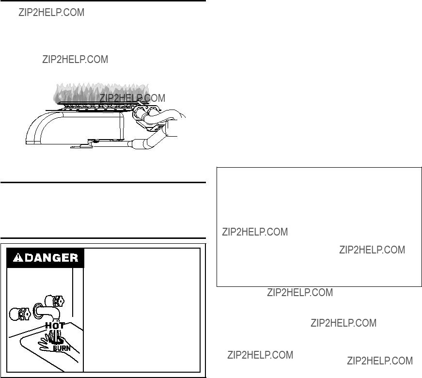
Temperature and Pressure Relief Valve
Explosion Harzard
??? Temperature-pressure relief valve must comply with ANSI Z21.22-CSA 4.4 and ASME code.
??? Properly sized temperature- pressure relief valve must be installed in opening provided.
??? Can result in overheating and excessive tank pressure.
??? Can cause serious injury or death.
Manually operate the temperature and pressure relief valve at least once a year to make sure it is working properly. To prevent water damage, the valve must be properly connected to a discharge line which terminates at an adequate drain. Standing clear of the outlet (discharged water may be hot), slowly lift
and release the lever handle on the temperature and pressure relief valve to allow the valve to operate freely and return to its closed position. See Figure 34. If the valve fails to completely reset and continues to release water, immediately shut off the electrial power, manual gas control valve and the cold water
inlet valve and call a qualified technician. Contact Sears Service 1-800-4-MY-HOME?? (www.sears.com).
TEMPERATURE AND PRESSURE
RELIEF VALVE
MANUAL RELIEF
 VALVE
VALVE
DISCHARGE LINE TO DRAIN
FIGURE 34.
???Soot and/or carbon on the main burner. Contact a qualified technician.
???Leaking or damaged water and gas piping.
???Presence of flammable or corrosive materials in the installation area.
???Presence of combustible materials near the water heater.
???After servicing this water heater, check to make sure it is working properly. (See ???Operating Your Water Heater??? section of this manual.)
IMPORTANT: If you lack the necessary skills required to properly perform this visual inspection, you should not proceed, but get help from a qualified technician.
MAINTENANCE OF YOUR WATER HEATER
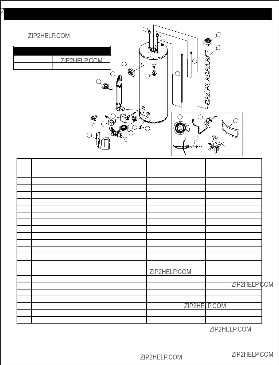
Replacement Parts
IMPORTANT: The following maintenance procedures are for the FVIR System components and should be performed by a qualified technician.
Replacement parts may be ordered from Sears Parts and Service Centers or by calling 1-800-4-MY-HOME (1-800-469-4663). When ordering replacement parts, always have the following information ready:
1.model, serial, and product number
2.type of gas
3.item number
4.parts description
See ???Parts Order List??? section for a list of available repair parts.
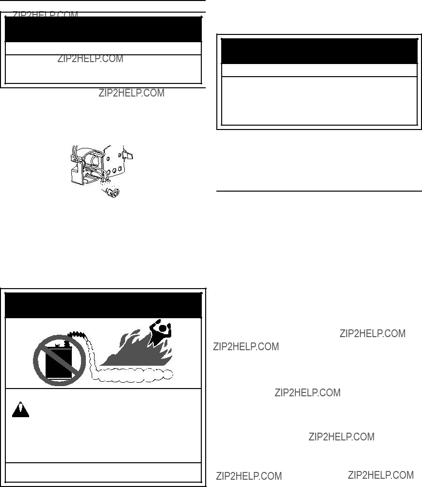
Removing the Manifold/Burner Assembly
1.Turn off the gas supply to the water heater at the manual gas shut-off valve. This valve is typically located beside the water heater. Note the position of the shut-off valve in the open/on position then proceed to turn it off (Figure 12).
2.Disconnect power supply to the heater.
3.Remove the outer door. Remove the 2 screw securing the manifold door assembly to the skirt.
4.Disconnect all wiring connectors from the gas control valve/ thermostat (Figure 35). Disconnect the manifold tube at the gas control valve/thermostat.
5.Grasp the manifold tube and push down slightly to free the manifold from the gas control valve/thermostat.
6.Carefully remove the manifold assembly from the burner com- partment. NOTE: Be sure not to damage internal parts (Figure 39).
7.Check the burner to see if it is dirty or clogged. The burner may be cleaned with soap and hot water.
Gas Control Valve/
Thermostat
FIGURE 35.
Removing the Burner from the Manifold/ Burner Assembly
Natural Gas Burner
1.Take off the burner by removing the two (2) screws located underneath the burner.
2.Check the burner to see if it is dirty or clogged. The burner may be cleaned with soap and hot water (Figure 36).
Screws
Igniter/Flame
Sense Connector
Burner
(Bottom View)
FIGURE 36.
Replacing the Flame Sense/Hot Surface igniter Assembly
1.Remove the manifold/burner assembly. See Removing the Manifold/Burner Assembly.
2.Lift the retainer clip straight up from the back of the manifold component block (using a flat-blade screwdriver), then remove the manifold component block from the manifold door (Figure 37.)
3.Remove and keep the screw securing the flame sense/hot surface igniter assembly (Figure 37)
4.Remove and discard the old flame sense/hot surface igniter assembly.
5.Route the new flame sense/hot surface igniter connector wire through manifold/burner door opening as shown in figure 37. Secure assembly to bracket using screw removed earlier.
TROUBLESHOOTING GUIDE
Start Up Conditions
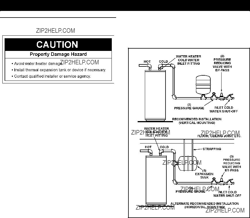
NOTE: Expansion tanks are pre-charged with a 40 psi air
Thermal Expansioncharge. If the inlet water pressure is higher than 40 psi, the expansion tank???s air pressure must be adjusted to match
that pressure, but must not be higher than 80 psi.
As water is heated, it expands (thermal expansion). In a closed system, the volume of water will grow. As the volume of water grows, there will be a corresponding increase in water pressure due to thermal expansion. Thermal expansion can cause premature tank failure (leakage). This type of failure is not covered under the limited warranty. Thermal expansion can also cause intermittent temperature-pressure relief valve operation: water discharged from the valve due to excessive pressure build up. The temperature-pressure relief valve is not intended for the constant relief of thermal expansion. This condition is not covered under the limited warranty.
A properly sized thermal expansion tank should be installed on all closed systems to control the harmful effects of thermal expansion. Thermal expansion tanks are available from Sears stores and through the Sears Service Centers. Contact the local plumbing inspector, water supplier and/or the Sears Service Center for assistance in controlling these situations. See Figure 41.
Thermal Expansion Tank Specifications
TABLE 6
Expansion Tank Sizing Chart
TABLE 7
*Highest recorded inlet water pressure in a 24 hour period or regulated water pressure.
FIGURE 41.
Strange Sounds
Possible noises due to expansion and contraction of some metal parts during periods of heat-up and cool-down do not represent harmful or dangerous conditions.
Condensation causes sizzling and popping within the burner area during heating and cooling periods and should be considered normal. See ???Condensation??? section.
Draft Hood Operation
Check draft hood operation by performing a worst case depressurization of the building. With all doors and windows closed, and with all air handling equipment and exhaust fans operating such as furnaces, clothes dryers, range hoods and bathroom fans, a match flame should still be drawn into the draft hood of the water heater with its burner firing. If the flame is not
drawn toward the draft hood, shut off water heater and make necessary air supply changes to correct.
B.*Condensation may be seen on pipes in humid weather or pipe connections may be leaking.
C.*The anode rod fitting may be leaking.
D.Small amounts of water from temperature-pressure relief valve may be due to thermal expansion or high water pressure in your area.
E.*The temperature-pressure relief valve may be leaking at the tank fitting.
F.Water from a drain valve may be due to the valve being slightly opened.
G.*The drain valve may be leaking at the tank fitting.
H.Combustion products contain water vapor which can condense on the cooler surfaces of the tank. Droplets form and drip onto the burner or run on the floor. This is common at the time of start-up after installation and when incoming water is cold.
I.Water in the water heater bottom or on the floor may be from condensation, loose connections, or the relief valve. DO NOT replace the water heater until a full inspection of all possible water sources is made and necessary corrective steps taken.
Leakage from other appliances, water lines, or ground seepage should also be checked.
*To check where threaded portion enters tank, insert cotton swab between jacket opening and fitting. If cotton is wet, follow draining instructions in the ???Draining and Flushing??? section and then remove fitting. Put pipe dope or teflon tape on the threads and replace. When you are finished, follow the steps in ???Filling the Water Heater??? in the Installation Instructions earlier in this manual.
Teflon?? is a registered trademark of E.I. Du Pont De Numours and Company.
Read this manual first. Then, before checking the water heater, make sure the gas supply has been turned ???OFF???, and never turn the gas ???ON??? before the tank is completely full of water.
Never use this water heater unless it is completely filled with water. To prevent damage to the tank, the tank must be filled with water. Water must flow from the hot water faucet before turning ???ON??? gas to the water heater.
A.Water at the draft hood is water vapor which has condensed out of the combustion products. This is caused by a problem in the vent. Contact a qualified technician.
ELECTRONIC CONTROL DISPLAY TROUBLESHOOTING
ELECTRONIC CONTROL DISPLAY
Please check guidelines below. For your safety, water heater service should be performed only by a qualified service person. Read the GENERAL SAFETY INFORMATION supplied by the water heater manufacturer.
TROUBLESHOOTING FLOWCHART
Get it fixed, at your home or ours!
Your Home
For troubleshooting, product manuals and expert advice:
www.managemylife.com
For repair ??? in your home ??? of all major brand appliances, lawn and garden equipment, or heating and cooling systems, no matter who made it, no matter who sold it!
For the replacement parts, accessories and owner???s manuals that you need to do-it-yourself.
For Sears professional installation of home appliances and items like garage door openers and water heaters.
1-800-4-MY-HOME?? (1-800-469-4663)
Call anytime, day or night (U.S.A. and Canada)
www.sears.com www.sears.ca
Our Home
For repair of carry-in items like vacuums, lawn equipment, and electronics, call anytime for the location of your nearest
Sears Parts & Repair Service Center
To purchase a protection agreement on a product serviced by Sears:
1-800-827-6655 (U.S.A.)
Para pedir servicio de reparaci??n a domicilio, y para ordenar piezas:
1-888-SU-HOGAR??
(1-888-784-6427) www.sears.com
1-800-361-6665 (Canada)
Au Canada pour service en fran??ais:
1-800-LE-FOYERMC
(1-800-533-6937) www.sears.ca
??Registered Trademark / TM Trademark of KCD IP, LLC in the United States, or Sears Brands, LLC in other countries
??Marca Registrada / TM Marca de F??brica de KCD IP, LLC en Estados Unidos, o Sears Brands, LLC in otros pa??ses MC Marque de commerce / MD Marque d??pos??e de Sears Brands, LLC


 WARNING


 FV Sensor
 WARNING
 Do not store or use gasoline or other flammable vapors and liquids in the vicinity of this or any other appliance. Storage of or use of gasoline or other flammable vapors or liquids in the vicinity of this or any other appliance can result in serious injury or death.
 WARNING
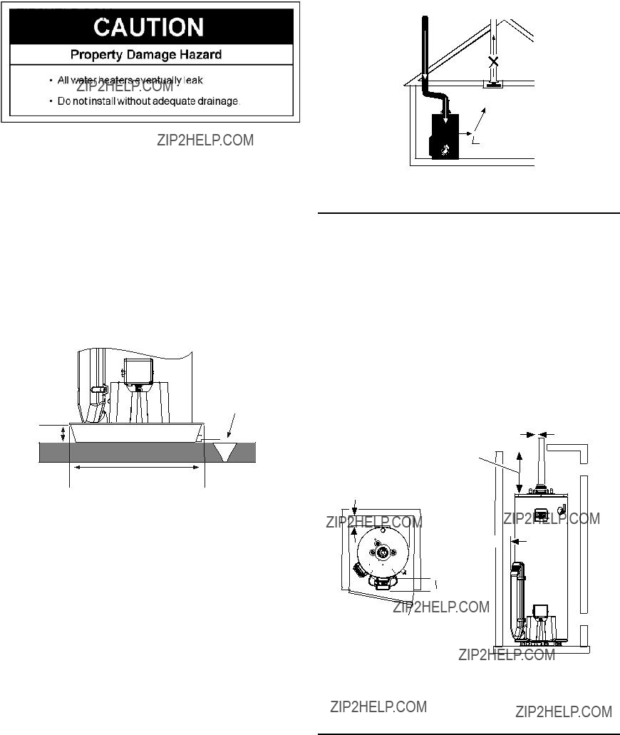

 Sides
Sides Air Inlet Chamber
 5??? min.
 Front
Front
 WARNING

 6??? Max. Air Gap
 Suitable Drain
 WARNING
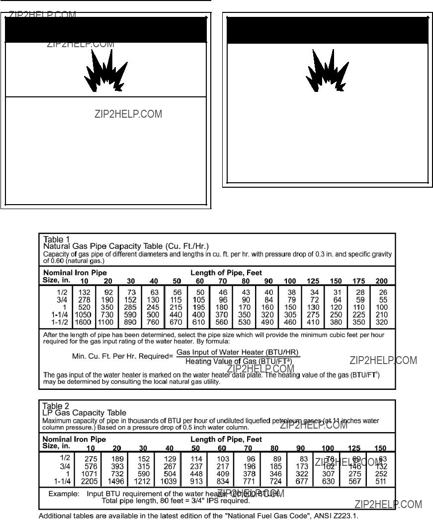
 WARNING
 WARNING


 Outlet Air to the Attic 1 sq. in. per 4000 BTUH
 12??? Max.
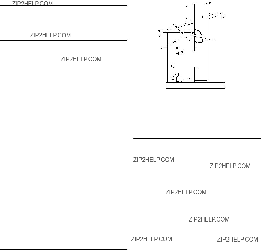
 Mixed Water
 Cold Water
 6??? Max.
 Drain
Drain
 WARNING


 showering.
 button decreases temperature and pressing the ???HOTTER???
 button increases the temperature.
 button until the desired setting is reached.
 button until the desired setting is reached.
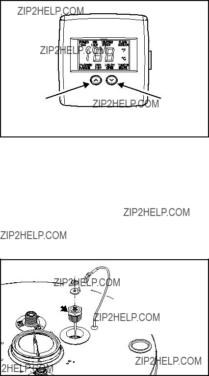
 button to its lowest setting. This will maintain the water at low temperatures with minimum energy losses and prevent the tank from freezing during cold weather.


 COOLER
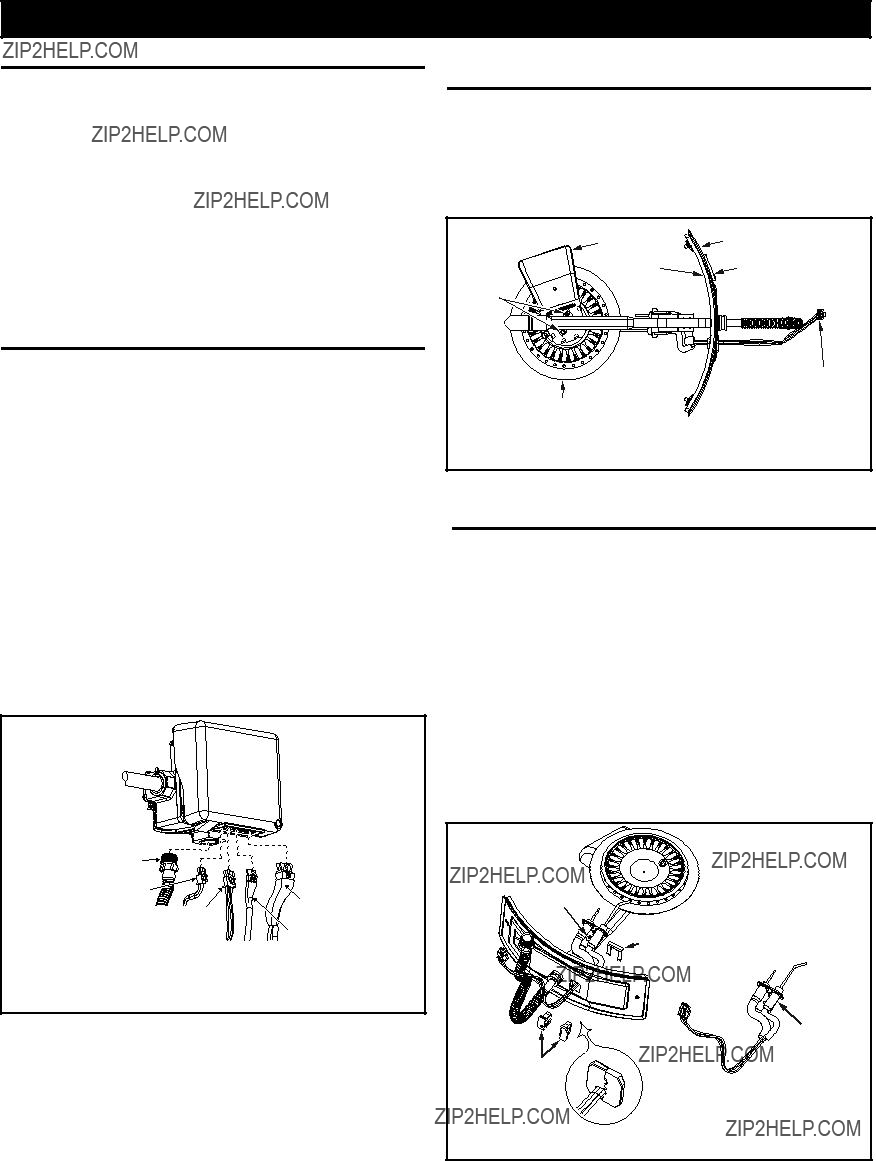


 WARNING
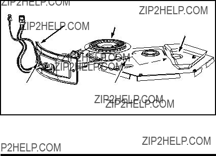
 and HOTTER
 buttons together and hold for 1 second. Then press the COOLER
 button until the VAC indicator light appears (Figure 32).