CONGRATULATIONS on your purchase of a Sears Craftsman Tiller?? it has been des=gned, engineered and
manufactured to give you the best possibledependability and performance.
Should you experience any problems you cannot easily remedy, please contact your nearest Sears Service Cen- teriDepartmentoWe have competent,well trained techni- cians and the proper tools to service or repair this unit
Please read and retain this manual. The instructionswill
enable you to assembleand maintain your Tiller prop- erty, Always observe the SAFETY RULES
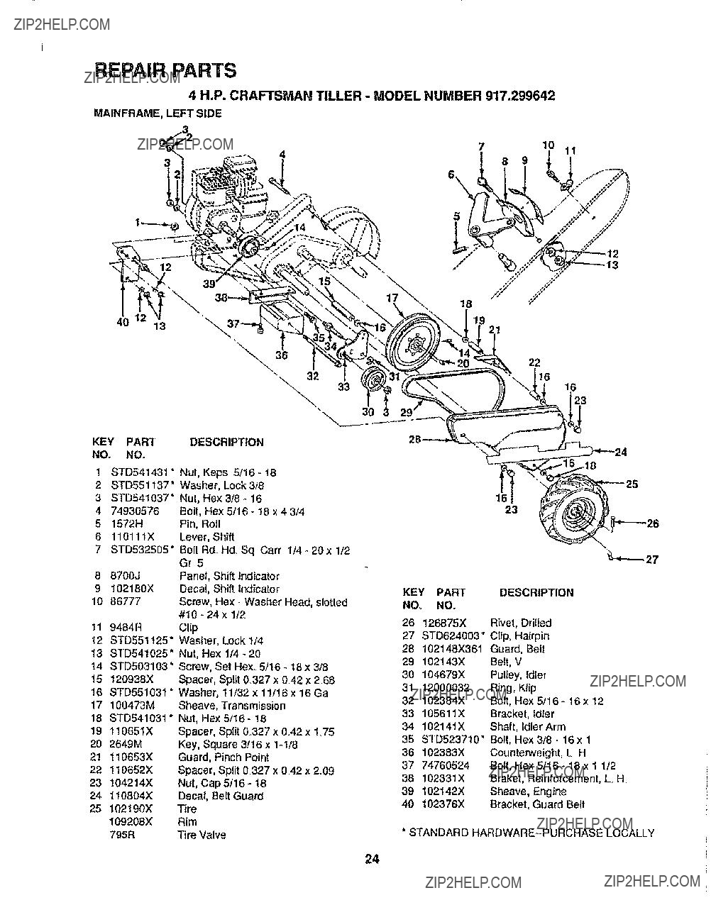
MODEL
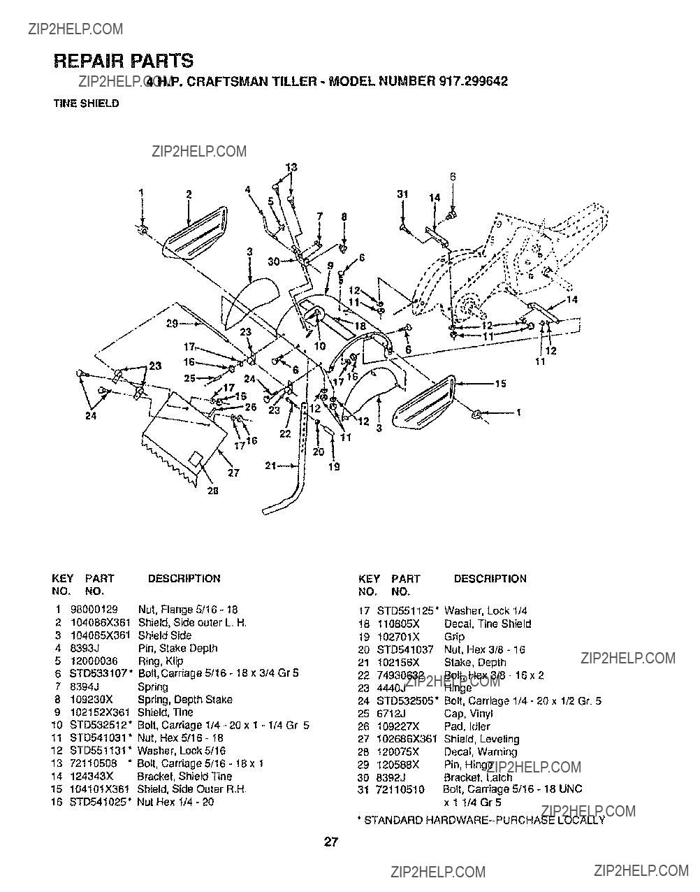
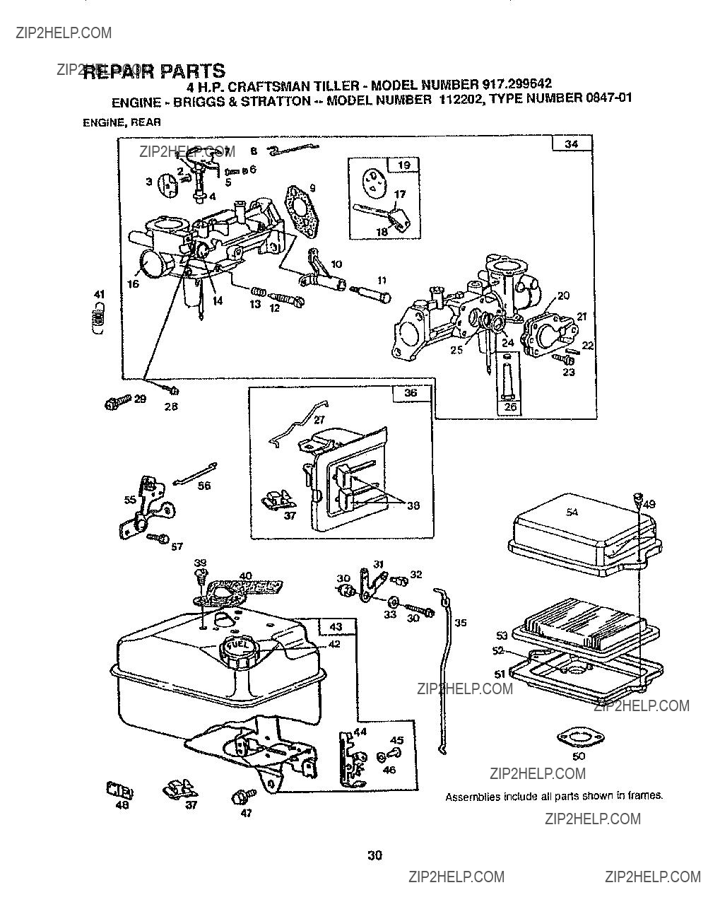
NUMBER 917.299642
SERIAL
NUMBER
DATE OF
PURCHASE
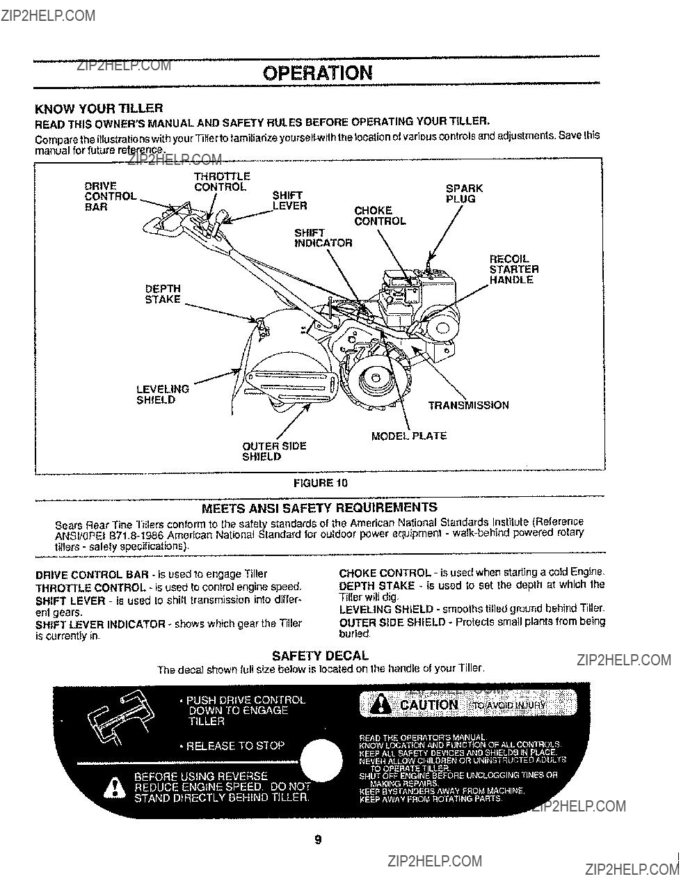
THE MODEL AND SERIAL NUMBERS WILL BE
FOUND ON THE MODEL PLATE ATTACHED TO
THE TOP OF THE TRANSMISSION,
YOU SHOULD RECORD BOTH SERIAL NUMBER
AND DATE OF PURCHASE AND KEEP IN A SAFE
PLACE FOR FUTURE REFERENCE,,
SPARK PLUG (GAP ,030 IN,): CHAMPION RCJ8
MAINTENANCE AGREEMENT
A Sears Maintenance Agreement is available on this product. Contact your nearest Sears store'fordetails,
CUSTOMER RESPONSIBILITIES
. Read and observe the safety rules.
??? Follow a regular schedule in maintaining, caring for and using your Tiller_
. Fo_towthe instructionsunder Maintenance" and "Storage" sections of this Owner'sManual,,
LIMITED ONE YEAR LIMITED WARRANTY ON CRAFTSMAN TILLER
For one year from date of purchase, when this Craftsman Tiller is maintained, lubricated, and tuned up ac- cording to the instructions in the owner s manual, Sears wilt repair, free of charge, any detect in material and
workmanship,,
If this Craftsman Tiller is used for commercial or rental purposes, this Warranty applies for only 30 days from the date of purchase.
This Warranty does not cover:
??? expendable items which become worn during normal use, such as tines, spark plug, air cleaners and bells,
???Repairs necessary because of operator abuse or negligence, including bent crankshafts and the failure to maintain the equipment according to the instructions contained in the owner'smanual
WARRANTY SERVICE IS AVAILABLE BY RETURNING THE CRAFTSMAN TILLER TO THE NEAREST
SEARS SERVICE CENTER/DEPARTMENT IN THE UNITED STATES. THIS WARRANTY APPLIES ONLY WHILE THIS PRODUCT iS IN USE IN THE UNITED STATES
This Warranty gives you specific legal rights, and you may also have other rights which vary from state to state.,
Sears, Roebuck and Co., D/731CR-W, Sears Tower, Chicago, IL 60684
-NOTE-
This unit is equipped with an internal combustion engine and should not be used on or near any unimprovedforest- covered, brush-covered or grass covered land unless the engine'sexhaust system is equipped with a spark arrester meeting applicable local or state laws (if any). If a spark arrester is used, it should be maintained in effectiveworkingorder by the operator.
in the state of California the above is required by law (Section 4442 of the California Public Resources Code) Other states may have similar laws. Federal laws apply on federal lands, See your Sears Authorized Service Center for spark arrester. Refer to page 33 of Repair Parts section of this manual for part number.