Owner's Manual

??

46"- 2 STAGE SNOW THROWER

TRACTOR ATTACHMENT

Model No. 486.248463

CAUTION:

Before using this product, read this manual and follow all Safety

Rules and

Operating Instructions.

IMPORTANT - READ THIS FIRST!!!

For Missing Parts or Assembly Questions

Please Call 866-576-8388

Mon.-Fri. 7 am - 5 pm CST.

FAX 217-728-2032 or e-mail info@agri-fab.com

Missing parts will be sent UPS in 24 hours directly to your home.

Sears, Roebuck and Co., Hoffman Estates, IL 60179 U.S.A.

www.sears.com/craftsman

???Safety

???Assembly

???Operation

???Maintenance

???Parts

TABLE OF CONTENTS

WARRANTY

LIMITED ONE YEAR WARRANTY ON 46" 2-STAGE SNOW THROWER

For one year from the date of purchase, when this snow thrower is maintained and lubricated according to the operating and maintenance instructions in the owner's manual, Sears will repair any defect in material or workmanship free of charge. If this snow thrower is used for commercial or rental purposes, this warranty applies for only 90 days from the date of purchase.

This warranty does not cover repairs necessary because of operator negligence or abuse, including the failure to maintain the equipment according to instructions contained in the owner's manual.

WARRANTY SERVICE IS AVAILABLE BY CONTACTING THE NEAREST SEARS SERVICE CENTER/DEPARTMENT

IN THE UNITED STATES.

This warranty applies only while this product is in the United States.

This warranty gives you speci??? c legal rights, and you may also have other rights which vary from state to state.

Sears, Roebuck and Co. D/817 WA. Hoffman Estates, Chicago, IL 60179

ACCESSORIES AND ATTACHMENTS

These accessories were available when the unit was purchased. They are also available at most Sears retail outlets and service centers. Most Sears stores can order repair parts for you when you provide the model numbers of your tractor and snow thrower.

The model number and serial numbers will be found on a decal attached to the snow thrower.

You should record both the serial number and the date of purchase and keep in a safe place for future reference.

2

SAFETY

Any power equipment can cause injury if operated improperly or if the user does not understand how to operate the equipment.

Exercise caution at all times, when using power equipment.

???Read this owner's manual carefully and know how to operate your snow thrower and how to stop the unit and disengage the controls quickly.

???Never allow children to operate the equipment.

???Never allow adults to operate the equipment without proper instruction.

???Keep the area of operation clear of all persons, especially small children, and pets.

???Thoroughly inspect the area where the equipment is to be used and remove all door mats, sleds, boards, wires and other foreign objects.

???Disengage all clutches and shift into neutral before starting engine.

???Do not operate equipment without wearing adequate winter outer garments.

???Wear substantial footwear which will protect feet and improve footing on slippery surfaces.

???Check fuel before starting the engine. Do not remove the fuel cap or ??? ll the fuel tank while the engine

is running or hot. Do not ??? ll the fuel tank indoors.

Gasoline is an extremely ??? ammable fuel.

???Make sure the snow thrower height is adjusted to clear the type surface it will be used on.

???Do not use the snow thrower without the rear weight attached to the tractor.

???Never make any adjustments while the engine is running.

???Always wear safety glasses or eye shield during operation or while performing and adjustment or repair.

???Do not place hand or feet near rotating parts. Keep clear of the discharge opening at all times.

???Use extreme caution when operating on or crossing gravel surfaces.

???Do not carry passengers.

???After striking a foreign object, stop the engine, remove the wire from the spark plug and then thoroughly inspect the snow thrower for damage. Repair any damage before restarting and operating the snow thrower.

???If the snow thrower starts to vibrate abnormally, stop the engine immediately and check for the cause. Vibration is generally a warning of trouble.

???Stop the engine whenever you leave the operating position, before unclogging the snow thrower or making any adjustments or inspections.

???Take all possible precautions when leaving the unit unattended. Disengage the attachment clutch lever or switch, lower the snow thrower, shift into neutral, set the parking brake, stop the engine and remove the key.

???When cleaning, repairing or inspecting, make certain all moving parts have stopped. Disconnect the spark plug wire and keep it away from the plug to prevent accidental starting.

???Do not run engine indoors except when transporting the snow thrower in or out of the building. Open the outside doors. Exhaust fumes are dangerous.

???Do not clear snow across the face of slopes. Exercise extreme caution when changing direction on slopes.

Do not attempt to clear steep slopes. Refer to the slope guide on page 23 of this manual.

???Never operate the snow thrower without guards, plates or other safety protection devices in place.

???Never operate the snow thrower near glass enclosures, automobiles, window wells, drop offs etc. without proper adjustment of the snow thrower discharge angle.

???Never direct discharge at bystanders or allow anyone in front of the snow thrower.

???Never run the snow thrower into material at high speeds.

???Do not overload the machine capacity by attempting to clear snow at too fast a rate.

???Never operate the machine at high transport speed on slippery surfaces. Look behind and use care when backing.

???Watch for traf??? c and stay alert when crossing or operating near roadways.

???Disengage power to the snow thrower when transporting or when not in use.

???Use only attachments and accessories approved by the manufacturer of the snow thrower (such as wheel weights, counter weights, cabs etc.)

???Never operate the snow thrower without good visibility or light.

Look for this symbol to point out important safety precautions. It mean--Attention!! Become alert!! Your safety is involved.

3

HARDWARE PACKAGE CONTENTS

SHOWN ACTUAL SIZE

A B C

L

I

M

J

N

K

Two shear bolts (R) and hex lock nuts (S) are provided as replacement parts for the spiral augers. Store in a safe place until needed. (See page 16.)

TU

A2 Hex Bolt, 3/8" x 1-1/2"

B4 Hex Bolt, 3/8" x 1-1/4"

C10 Hex Bolt, 3/8" x 1"

D2 Hex Bolt , 5/16" x 1-3/4"

E6 Hex Bolt, 1/4" x 1"

F2 Carriage Bolt, 5/16" x 1-3/4"

G6 Carriage Bolt, 5/16" x 1"

H2 Shoulder Bolt

I10 Hex Nut, 5/16"

J6 Flanged Lock Nut, 1/4"

K12 Hex Lock Nut, 3/8"

L10 Lock Washer, 5/16"

M18 Lock Washer, 3/8"

D E F GH

RS

OQ

P

NOT SHOWN ACTUAL SIZE

V

W

Y

X

REF. QTY. DESCRIPTION

N2 Bowed Washer

O6 Washer, 1/4"

P2 Washer, 5/16"

Q2 Washer, 3/4"

R 8 Spacer

S4 Hairpin Clip

T2 Shear Bolt

U2 Hex Lock Nut, 5/16"

V1 Tarp Strap

W3 Chute Keeper

X1 Plastic Grip

Y2 Lock Pin

4

ASSEMBLY

CARTON CONTENTS

9

10

13

11

14

15

19

16

5

TOOLS REQUIRED FOR ASSEMBLY

(2) 7/16" Wrenches

(2) 1/2" Wrenches

(2) 9/16" Wrenches

(1) 5/8" Wrench or Adjustable Wrench

(1) 11/16" Wrench or Adjustable Wrench

(1) 3/4" Wrench or Adjustable Wrench

(1)Knife

General Purpose Grease

REMOVAL OF PARTS FROM CARTON

???Remove all parts and hardware packages from the carton. Lay out all parts and hardware and identify using the illustrations on pages 4 and 5.

CAUTION: Before starting to assemble the snow thrower, remove the spark plug wire(s), set the parking brake and remove the key from the tractor ignition.

TRACTOR PREPARATION

Before proceeding with these instructions, refer to the

Service and Adjustments section of your tractor owner's manual for speci??? c safety instructions.

???Allow engine, muf??? er and exhaust de??? ector to cool before beginning.

???Remove any front or rear attachment which is mount- ed to your tractor.

Remove the mower deck. Refer to your tractor owner's manual for removal instructions. Mark all loose parts and save for reassembly.

???Remove the tractor hood and grill assembly. Refer to your tractor owner's manual for removal instructions.

ITEMS REMOVED FROM TRACTOR

Store all brackets and fasteners removed from the trac- tor during the assembly of the snow thrower, unless the instructions call for their use.

ASSEMBLING PARTS TO TRACTOR FRAME

Right hand (R.H.) and left hand (L.H.) are determined from the operators position while seated on the tractor.

???Remove the hex bolt from the threaded hole at the top front corner of R.H. front suspension bracket.

???Remove either a or b depending on tractor:

a.the hex bolt from the threaded hole at the top rear corner of R.H. front suspension bracket.

b.the nut from the carriage bolt at the top rear corner of the bracket, leaving the carriage bolt in the tractor frame. See ??? gure 1.

???Repeat for the L.H. front suspension bracket.

FRONT SUSPENSION

BRACKET (R.H.)

???Attach the front of the side plate to the threaded hole in the tractor frame using a 3/8" x 1" hex bolt and a 3/8" lock washer. Attach the rear of the R.H. side plate to the tractor using either a 3/8" x 1" hex bolt and lock washer or a 3/8" hex lock nut and lock washer. Repeat for the L.H. side. See ??? gure 2.

NOTE: If the side plates are removed from the tractor frame, be sure to reassemble bolts and nuts back into the frame.

3/8" x 1"

HEX BOLT

SIDE PLATE (R.H.)

6

If you have a 54" mower deck go directly to page 8. All other deck sizes use the following instructions.

???Remove the mower stop bracket and its two bolts and nuts from the R.H. side of the tractor frame as shown in ??? gure 3.

???If the tractor has a muf??? er guard at the front of the R.H. foot rest, remove the bottom bolt and nut, and the washer which is located between the guard and the tractor frame. See ??? gure 3.

???Remove the two bolts from the bottom of both the

R.H. and L.H. foot rests. See ??? gure 3.

MUFFLER GUARD

(ONLY MODELS WITH

SIDE MUFFLER)

MOWER STOP

BRACKET

???Assemble the R.H. hanger bracket to the bottom hole where the mower stop bracket was removed and to the upper hole under the front of the foot rest. Fasten with two 3/8" x 1" hex bolts, 3/8" lock washers and 3/8" hex lock nuts. (On tractors with muf??? er guards, slide the hanger bracket between the guard and the tractor frame.) See ??? gure 4.

MUFFLER GUARD

(ONLY MODELS WITH

SIDE MUFFLER)

R.H. HANGER

BRACKET

???Assemble the L.H. hanger bracket to the left side of the tractor frame using two 3/8" x 1" hex bolts, two 3/8" lock washers and two 3/8" hex lock nuts as shown in ??? gure 5.

3/8" HEX

LOCK NUT

3/8" x 1"

HEX BOLT

???Assemble a frame bracket to the L.H. foot rest and sway bar bracket as shown in ??? gure 6. Use two 3/8" x 1-1/4" hex bolts, three spacers and two 3/8" lock washers.

???Assemble a shoulder bolt to the inside of the L.H. frame bracket, securing it with a 3/8" lock washer and a 3/8" hex lock nut. See ??? gure 6.

???Repeat with a frame bracket on the R.H. side of the tractor. Attach in the same manner but use four spacers (two per bolt).

???Proceed to page 9.

7

This page for tractors with 54" mower decks only.

???Remove and store the mower stop bracket and bolt from both sides of the tractor frame. See ??? gure 3.

???Remove the two bolts from the bottom of the foot rests on both sides of the tractor frame. See ??? gure 7.

54" MOWER DECKS

MOWER STOP

BRACKET

???Assemble the 54" R.H. hanger bracket to the holes where the mower stop bracket was removed on the right side of the tractor frame. Fasten with two 3/8" x 1" hex bolts, two 3/8" lock washers and one 3/8" hex lock nut. See ??? gure 8.

54" MOWER DECKS

???Assemble the 54" L.H. hanger bracket to the holes where the mower stop bracket was removed on the left side of the tractor frame. Fasten with two 3/8" x 1" hex bolts, two 3/8" lock washers and two 3/8" hex lock nuts. See ??? gure 9.

54" MOWER ECKS

L.H. HANGER

BRACKET (54")

3/8" x 1"

HEX BOLT

???Assemble a frame bracket to the L.H. foot rest as shown in ??? gure 10. Use two 3/8" x 1-1/4" hex bolts, four spacers (2 per bolt) and two 3/8" lock washers.

???Assemble a shoulder bolt to the inside of the frame bracket, securing it with a 3/8" lock washer and a 3/8" hex lock nut. See ??? gure 10.

???Repeat with a frame bracket on the R.H. side of the tractor

54" MOWER DECKS

(2) SPACERS

SHOULDER

BOLT

8

ATTACHING CLUTCH/IDLER ASSEMBLY

???Connect the end link of each chain to the springs shown in ??? gure 11.

If your mower deck is 48" or 54" skip this paragraph.

???If you have a mower deck smaller than 48", measure the outer diameter of the tractor's engine pulley. If the diameter of the pulley is less than 6", move the inside hairpin clip in the L.H. adjusting chain from link #8 to link #5. (Links are counted from the end of the chain attached to the spring).

ENGINE PULLEYS LESS THAN 6" IN DIAMETER

LINK #5 IN

L.H. CHAIN

R.H. CHAIN

FIGURE 11

If your mower deck is 54" skip this paragraph.

???Attach the rear of the clutch/idler assembly to the tractor frame by sliding the notched arms of the assembly onto the shoulder bolts assembled to the frame brackets. Lift the front of the assembly, positioning the upper idler pulley so that it clears the engine pulley. Attach the front of the assembly to the hanger brackets using two pivot lock pins and two hairpin clips. See ??? gure 12.

PIVOT LOCK PIN

HAIRPIN CLIP

This paragraph for 54" mowers only.

???Attach the rear of the clutch/idler assembly to the tractor frame by sliding the notched arms of the assembly onto the shoulder bolts assembled to the frame brackets. Lift the front of the assembly, positioning the upper idler pulley so that it clears the engine pulley. Attach the front of the assembly to the hanger brackets using two pivot lock pins and two hairpin clips. See ??? gure 13.

TRACTORS WITH 54" MOWER DECKS ONLY

PIVOT LOCK PIN

HAIRPIN CLIP

FIGURE 13

9

ASSEMBLY OF SNOW THROWER

???Place the lift handle into the lift bracket on the right side of the snow thrower. Fasten the handle to the bracket using two 5/16" x 1-3/4" hex bolts, 5/16" lock washers and 5/16" hex nuts. See ??? gure 14.

???Remove the nylon tie which fastens the chute crank rod to the crank support tube.

???Assemble the crank support tube (??? at side) to the two brackets on the left side of the thrower housing using two 3/8" x 1-1/2" hex bolts, 3/8" lock washers and 3/8" hex lock nuts. See ??? gure 16.

5/16" x 1-3/4"

HEX BOLT

LIFT BRACKET

5/16" HEX NUT

5/16" LOCK

WASHER

NOTE: Be sure the lift release cable's plastic covering remains inserted into the trigger assembly while completing the next step.

???Push the lift handle down into the locked position. Insert the end of the cable wire into the hole in the lift rod. Place the threaded ??? tting into the slot in the lift bracket, with one hex nut above and one hex nut and the lock washer below the slot. Tighten the nuts, adjusting them to eliminate slack in the cable wire. See ??? gure 15. Refer also to the Service and

Adjustments section on page 18 in this manual.

???Attach the chute tilt control assembly to the top side of the crank support tube using two 5/16" x 1-3/4" carriage bolts, bowed washers, 5/16" lock washers and 5/16" hex nuts. See ??? gure 17.

CHUTE CRANK ROD

CRANK SUPPORT TUBE

TILT CONTROL HANDLE

???Attach the chute crank assembly to the plastic bracket on the left side of the thrower housing as shown in

??? gure 18. Use two 5/16" x 1" carriage bolts, 5/16" ??? at washers, 5/16" lock washers and 5/16" hex nuts. Do not tighten yet.

10

5/16" x 1"

CARRIAGE BOLT

CHUTE CRANK

ASSEMBLY

5/16" LOCK

WASHER

???Coat the top of the ring around the discharge opening with general purpose grease. See ??? gure 19.

???Place the discharge chute (facing forward) onto the discharge opening, aligning the crank rod spiral with the notches in the chute ??? ange.

???Attach the three chute keepers (right side up as shown in ??? gure 19) and the anti-rotation bracket to the bottom of the chute ??? ange. Use six 1/4" x 1" hex bolts, 1/4" ??? at washers and 1/4" ??? anged lock nuts. Tighten carefully so that the plastic parts are not deformed.

See ??? gure 19.

???Place the plastic grip onto the back end of the anti- rotation bracket. See ??? gure 19.

???Position the chute crank assembly so that the crank rod spiral does not rub the bottoms of the notches in the chute ??? ange and then tighten the nuts left loose in ??? gure 19.

???Check if the crank rod rotates the chute freely. If not, loosen by 1/4 turn each the six ??? anged nuts holding the chute keepers to the chute ??? ange.

MOUNTING SNOW THROWER TO TRACTOR

NOTE: The help of another person may be required to mount the snow thrower to the front of the tractor.

???Place the tractor and snow thrower on a ??? at, level surface.

???Remove the plastic tie from the auger belt and extend the belt out behind the snow thrower, making sure the belt remains assembled around the top of the large auger drive pulley and passing underneath the two side idler pulleys.

???Align the tractor behind the snow thrower.

???Remove the attachment pin from the snow thrower.

???Squeeze the release trigger on the lift handle and raise the handle out of the locked position. (If the handle will not release out of the locked position, refer to the Service and Adjustments section of this manual.)

???Grasp the round bar just behind the auger drive pulley and lift up to align the rear mounting notches on the snow thrower with the mounting pins on the tractor.

Slide the pins into the notches.

HINT: If you are unable to ??? t the mounting pins into the notches, try placing 1" or 2" blocks of wood under the front skid shoes on the snow thrower.

???Assemble a 3/4" washer and a 1/8" hairpin clip to each mounting pin.

???Secure the snow thrower to the tractor using the attachment pin and 1/8" hairpin clip. Insert the attachment pin from the left side. See ??? gure 20.

ATTACHMENT PIN

1/8" HAIRPIN CLIP

MOUNTING

PIN

1

ASSEMBLING THE BELTS

IMPORTANT: The tapered "V" section of the belts must be seated into the grooves of the V-pulleys.

DRIVE BELT

???Remove the two outside 1/8" hairpin clips which are assembled to the L.H. and R.H. tension adjusting chains outside of the clutch idler assembly frame.

(The clips will be reinstalled after both belts have been assembled.) Do not remove the 3/32" hairpin clips assembled to the chains on the inside of the assembly frame. See ??? gure 21.

???Assemble the drive belt onto the tractor's engine pulley and then onto the upper rear pulley on the clutch/idler assembly. Keep the ??? at idler pulley on the outside of the belt. See ??? gure 21.

Hold this diagram above you while viewing the

Clutch/Idler Assembly from underneath the tractor. Right and left in this diagram will be the reverse of the viewer's right and left.

1/8"

HAIRPIN

CLIP

1/8"

HAIRPIN

CLIP

AUGER BELT

???Make sure the auger belt is correctly assembled to the snow thrower. The belt must pass over the top of the auger pulley and then twist 1/4 turn to pass underneath the two side idler pulleys on the snow thrower. The "V" side of the belt must seat in the grooves of all three pulleys. See ??? gure 22.

12

???Raise the snow thrower to the transport position.

???Place the uger belt around the bottom rear pulley on the clutch/idler assembly and between the two pulleys on the lower idler arm. Keep the ??? at idler pulley to the outside of the belt. See ??? gure 23.

??? Pull the ??? at idler pulley against the uger belt using the R.H. tension adjusting chain. For correct belt tension, pull the chain as far as the inside hairpin clip will allow and then reinstall the outside 1/8" hairpin clip into the chain. See ??? gure 23.

IMPORTANT: If the R.H. inside hairpin clip is removed, reinstall it in link #4 (counted from the end of the chain attached to the spring).

???Pull the upper ??? at idler pulley against the drive belt using the L.H. tension adjusting chain. For correct belt tension, pull the chain as far as the inside hairpin clip will allow and then reinstall the outside 1/8" hairpin clip into the chain. See ??? gure 23.

IMPORTANT: If the L.H. inside hairpin clip is removed, reinstall it in link #8 on tractors with 6" diameter engine pulleys or in link #5 on tractors with smaller engine pulleys. (Links are counted from the end of the chain attached to the spring.)

Hold this diagram above you while viewing the

Clutch/Idler Assembly from underneath the tractor. Right and left in this diagram will be the reverse of the viewer's right and left.

ATTACHING WEIGHT TRAY TO TRACTOR

???Loosen the two hex bolts and nuts which fasten the top of the tractor drawbar to the rear of the tractor frame. See ??? gure 24.

???Assemble the notched end of the side brace arms down onto both loosened bolts. Do not tighten yet.

See ??? gure 24.

???Fasten the weight tray to the drawbar using two

3/8" x 1" hex bolts, 3/8" lock washers and 3/8" hex lock nuts. Do not tighten yet. See ??? gure 24.

???Fasten the weight tray to the side brace arms using two 5/16" x 1" carriage bolts, 5/16" lock washers and 5/16" hex nuts. Do not tighten yet. See ??? gure 24.

???Fasten the weight tray cross brace to the side brace

arms using two 5/16" x 1" carriage bolts, 5/16" lock washers and 5/16" hex nuts. Tighten all loose bolts at this time. See ??? gure 24.

13

???Place the weight keg on the weight tray and ??? ll with approximately 100 lbs. of dry sand.

???Secure the keg with the rubber tarp strap hooked into the holes in the cross brace. See ??? gure 25.

TARP STRAP

CHECKLIST

Before you operate your snow thrower, please review the following checklist to help ensure that you will obtain the best performance from your snow thrower.

???All assembly instructions have been completed with all bolts and nuts properly tightened.

???Check the engine belt and the auger belt. Make sure they are routed properly around pulleys and inside all belt keepers.

???Check discharge chute for proper rotation.

???Check operation of tilt control for upper chute.

???Verify that the snow thrower can be locked into and released from the raised transport position using the lift handle. (Refer to the Service and Adjustments section.)

Accessories

The following additional items are available from Sears to help enhance the performance of your snow thrower. See also page 2.

???Tire chains which can be installed to improve traction.

???Rear wheel weights which can be installed in addition to the rear weight tray to improve traction.

???Drift cutter bars which can be installed to help slice off the edges of tall drifts.

14

OPERATION

KNOW YOUR SNOW THROWER

Read this owner's manual and safety rules before operating your snow thrower.

Compare the illustration below with your snow thrower to familiarize yourself with the various controls and their locations.

SCRAPER PLATE

SPIRAL AUGERS, R.H. & L.H.

CHUTE TILT HANDLE Pivots the Upper Chute up or down to control the angle and distance of discharge.

CRANK ROD Rotates the Lower and Upper Chutes to control the direction of discharge.

LEVELING SHOE Helps maintain the snow thrower in a level position.

LIFT HANDLE Used to lift or lower the snow thrower to transport or operating position.

LIFT RELEASE TRIGGER Releases the lock which holds the snow thrower in the up, transport position.

LEVELING SHOE (Behind housing)

SKID SHOE

UPPER AND LOWER DISCHARGE CHUTE Controls direction and height of snow discharge.

SCRAPER PLATE Replaceable plate that absorbs wear and impact from contact with ground.

SKID SHOE Controls amount of clearance between the scraper plate and the ground.

SPIRAL AUGER, R.H. & L.H. Feed snow to the impeller fan at the center of the housing.

BEFORE STARTING

???Use the end of assembly checklist to verify that all instructions have been properly completed.

???Make sure the skid shoes are adjusted to maintain adequate ground clearance between the snow thrower and the type of surface to be cleared. The skid shoes are factory adjusted for clearing a smooth surface. (Refer to the Service and Adjustments section in this manual.)

???Make sure the tractor engine has the correct oil for winter operation. Refer to your tractor owner's manual.

HOW TO START YOUR SNOW THROWER

The tractor should be sitting with the engine running at full throttle. Pull the attachment clutch switch out to the engaged position, starting the snow thrower before starting the tractor in motion.

HOW TO STOP YOUR SNOW THROWER

???To stop the snow thrower, push in the attachment clutch switch on the tractor. Refer to the Operation section in your tractor owner's manual.

15

HOW TO USE YOUR SNOW THROWER

CAUTION: Never direct discharge towards bystanders or windows. Do not allow anyone in front of unit.

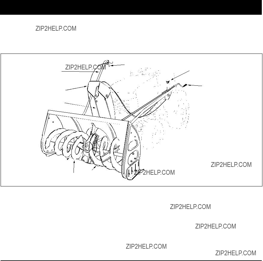
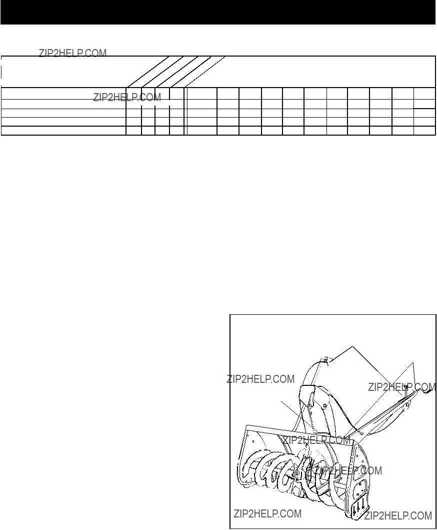
CONTROLLING SNOW DISCHARGE

???To control the direction snow is thrown, the discharge chute has 180 degrees of rotation. Turn the crank rod clockwise to rotate the chute to the right. Turn the crank rod counterclockwise to rotate the chute to the left.

???To control the distance snow is thrown, the upper section of the discharge chute pivots up and down. Push forward on the chute tilt handle to pivot the chute down, decreasing the distance snow is thrown. Pull back on the handle to pivot the chute up, increasing the distance snow is thrown.

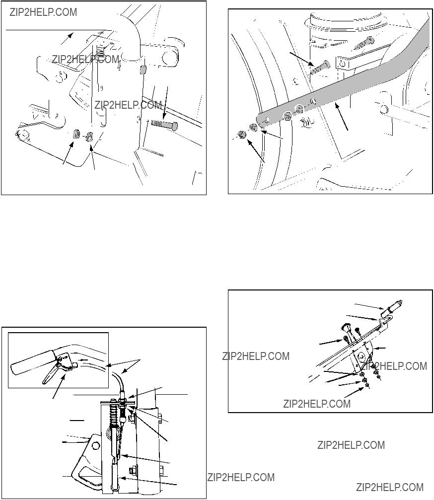
RAISING AND LOWERING

???To raise, push down on the lift handle until the snow thrower locks in the raised transport position.

???To lower, push down slightly on the lift handle and pull the trigger. With the trigger pulled, slowly lower the snow thrower until it reaches the ground.

CAUTION: Do not operate the snow thrower without the rear weight attached to the tractor to provide extra traction and stability.

REMOVING SNOW

Snow removal conditions vary greatly from light ??? uffy snowfall to wet heavy snow. Operating instructions must be ??? exible to ??? t the conditions encountered. The operator must adapt the lawn tractor and snow thrower to depth of snow, wind direction, temperature and surface conditions.

???Before beginning operation, thoroughly inspect the area of operation and remove all door mats, sleds, boards, wires and other foreign objects.

???The spiral auger speed is directly related to engine speed. For maximum snow removal and discharge, maintain high engine r.p.m. (full throttle). It is advisable to operate the lawn tractor at a slow ground speed

(1st gear) for safe and ef??? cient snow removal.

???In deep, drifted or banked snow it will be necessary to use full throttle and a slow ground speed (1st gear).

Drive forward into the snow, depress the tractor's clutch-brake pedal and allow the spiral auger to clear the snow. Repeat this method until a path is cleared.

On the second pass, overlap the ??? rst enough to allow the snow thrower to handle the snow without repeated stopping and starting of forward motion.

???In extremely deep snow, raise the snow thrower from the ground to remove the top layer and drive forward only until the tractors front tires reach the uncleared bottom layer of snow. Depress the tractor's clutch- brake pedal and allow the spiral auger to clear the snow. Reverse the tractor and lower the snow thrower to the ground. Drive the tractor forward until the snow again becomes too deep. Repeating this process into and out of drifts will eventually clear even the deepest of snow piles.

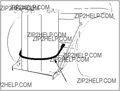
???If the snow thrower becomes clogged with snow or jammed with a foreign object, disengage the snow thrower immediately and shut off the tractor engine. Unclog the snow thrower before resuming operation.

DANGER: Shut off engine and disengage snow thrower before unclogging discharge chute. Unclog using a wooden stick, not your hands.

OPERATING TIPS

???Discharge snow down wind whenever possible.

???To help prevent snow from sticking to the snow thrower, allow the snow thrower to reach outdoor temperature before using it. A light coat of wax may also be applied to the inside surface of the snow thrower housing and discharge chute.

???Use tire chains to improve traction.

???Use rear wheel weights to improve traction.

???Before the ??? rst snowfall, remove all stones, sticks and other objects which could become hidden by the snow. Permanent obstacles should be marked for visibility.

???Overlap each pass slightly to assure complete snow removal.

16

MAINTENANCE

CUSTOMER RESPONSIBILITIES

???Read and follow the maintenance schedule and the maintenance procedures listed in this section.

MAINTENANCE SCHEDULE

Fill in dates as you complete regular service.

Check for loose fasteners Check belts for wear

Check scraper and shoes for wear Cleaning

Lubrication Section

X

X X

X

X X

X

Service Dates

CHECK FOR LOOSE FASTENERS

Before each use make a thorough visual check of the snow thrower for any bolts and nuts which may have loosened. Retighten any loose bolts and nuts.

CHECK BELTS FOR WEAR

Visually check both of the "V" belts on the snow thrower for wear or damage. Replace if the belt cover has become torn, frayed of is worn through.

CHECK SCRAPER AND SHOES FOR WEAR

(Refer to ???gures 27 and 28 on page 18.)

???The scraper plate, skid shoes and leveling shoes on the snow thrower are subject to wear through normal use. To prevent damage to the spiral auger housing, replace plate and shoes before wear is excessive.

CLEANING

???Clean out any dirt and debris from auger and impeller after each use.

???Before storing at the end of each season rinse out the auger and impeller housing. Allow to dry thoroughly.

???Before storing at the end of the season, paint any exposed metal surfaces to protect from rust.

LUBRICATION

Oil all pivot points on snow thrower lift mechanism.

???Oil upper and lower idler arm pivot points on the clutch/idler assembly.

???Apply a good grade of spray lubricant to the trigger assembly on the lift handle and the chute tilt control assembly and cables on the crank support tube. See

??? gure 26.

???Apply a small amount of oil between the inside of the discharge chute and the top of the discharge opening on the auger housing as needed to maintain easy rotation of the discharge chute. See ??? gure 26.

SPRAY

LUBRICANT

OIL

OIL

FIGURE 26

17

SERVICE AND ADJUSTMENTS

CAUTION: Before servicing or adjusting the snow thrower, shut off the engine, remove the spark plug wire(s), set the parking brake and remove the key from the tractor ignition.

REPLACING AUGER BELT

???Raise the snow thrower to the transport position.

???Release the spring tension on the drive belt idler.

???Release the spring tension on the auger belt idler.

???Remove the belt cover and loosen the belt keeper bracket (items 18 and 19 on page 20).

???Remove the auger belt from the clutch/idler assembly and from the spiral auger housing.

???Install new belt around top of auger drive pulley and underneath the two side idler pulleys. Twist the belt

1/4 turn to seat it in each idler pulley.

???Reinstall the belt cover and tighten the belt keeper bracket (items 18 and 19 on page 20).

???Assemble the belt onto the clutch/idler assembly as instructed for ??? gure 23 on page 13.

LIFT RELEASE CABLE ADJUSTMENT

???If the lift rod does not lock the snow thrower securely in the transport position, loosen the upper hex nut on the lift bracket a few turns and tighten the lower hex nut. See ??? gure 17 on page 10.

???If the lift rod fails to unlock completely to lower the snow thrower to the ground, loosen the lower hex nut on the lift bracket a few turns and tighten the upper hex nut. Refer to ??? gure 17 on page 10.

SPIRAL AUGERS

???The spiral augers are secured to the auger shaft with two shear bolts and hex lock nuts. If you hit a foreign object or if ice jams the augers, the snow thrower is designed so that the bolts will shear.

???If the augers will not turn, check to see if the shear bolts have sheared. See ??? gure 27. Two replacement shear bolts and hex lock nuts have been provided with the snow thrower. For future use order part number

710-0891 shear bolt and number 43064 hex lock nut.

SKID SHOE, LEVELING SHOE ADJUSTMENT

(The snow thrower must be attached to the tractor for correct adjustment of the shoes.)

???The skid shoes regulate the distance the scraper plate is raised above the plowing surface. They are mounted on each side of the spiral auger housing.

The leveling shoes help maintain the snow thrower in a level position. They are mounted just behind the auger housing.

???When removing snow from a gravel driveway or an uneven surface, it is advisable to keep the scraper plate as high above the surface as possible to prevent possible damage to the spiral auger. On a smooth blacktop or concrete surface, keep the scraper plate as close to the surface as possible.

???To adjust the skid shoes, raise the snow thrower off the ground and place a wood block under each end of the scraper plate. Loosen the six hex nuts securing the skid shoes to the housing. Adjust the skid shoes up or down to the desired position and tighten the nuts securely. Both skid shoes should be the same height to keep the housing and the scraper plate level.

See ??? gure 28.

???The skid shoes may be turned to face either in or out. In order to obtain the lowest setting, where the scraper blade fully contacts the ground, the skid shoes must be facing out as shown in ??? gure 28.

???Before adjusting the leveling shoes, make sure the skid shoes are properly adjusted. With the snow thrower in the lowered position, loosen the bolts which fasten the leveling shoes to the thrower and adjust the leveling shoes to solidly contact the ground. Retighten the bolts. See ??? gure 28.

LEVELING SHOE

FIGURE 28

FIGURE 27

18

STORAGE

STORAGE RECOMMENDATIONS

???Lower the snow thrower to the ground and remove it from the tractor.

???Clean the snow thrower thoroughly. Wash off any salt deposits which may have dried on the thrower and housing.

???Any bare metal that has become exposed should be painted or coated with a light oil to prevent rust.

???Store in a dry place.

REMOVING THE SPIRAL AUGER HOUSING

???Raise the snow thrower to the transport position.

???Release the spring tension from the auger belt idler arm on the bottom of the clutch/idler assembly.

???Remove the auger drive belt from the clutch/idler assembly. See ??? gure 23 on page 13.

???Lower the snow thrower to the ground.

???Remove the attachment pin and pull the auger housing assembly off of the tractor. Refer to ??? gure 20 on page 11.

HINT If the auger housing does not remove easily from the tractor, try placing 1" or 2" blocks of wood under the front skid shoes on the snow thrower. See the instructions for ??? gure 20 on page 11.

PARTS TO REMOVE AT END OF SEASON

???Remove the "V" belt from the engine pulley and the clutch/idler assembly. See ??? gure 21 on page 12.

???Remove the clutch/idler assembly. (The two hanger brackets and the two frame brackets should not create any interference with the mower deck and may be left attached to the tractor frame.)

???If a rear mounted attachment is to be used, remove the rear weight tray by removing the two bolts which fasten it to the tractor draw bar and by loosening the two bolts fastening the tray's brace arms to the tractor.

Be sure to retighten the two bolts and nuts which fastened the brace arms to the tractor. See ??? gure 24 on page 13.

???If a front mounted attachment is to be used, remove the side plates from the front of the tractor.

Be sure to reassemble the removed bolts and nuts to the tractor frame. See ??? gures 1 and 2 on page 6.

TROUBLESHOOTING

PROBLEM

Spiral augers stop turning

Clogged discharge chute

Snow thrower stalls tractor engine

Front wheels slide instead of steering

Snow thrower rides up over snow

Snow thrower rocks backward while blowing snow

1. Object jammed in spiral auger1. Stop engine, disengage the snow thrower and clear the auger

2. Hard or heavy snow2. Increase to full throttle and decrease ground speed

19

PARTS

REPAIR PARTS FOR MODEL 486.248463 46" SNOW THROWER

1

14

20

REPAIR PARTS FOR MODEL 486.248463 46" SNOW THROWER

2

REPAIR PARTS FOR MODEL 486.248463 46" SNOW THROWER

55

26

28

27

20

19

13

19

5

6

57

3

39

A

49

22

REPAIR PARTS FOR MODEL 486.248463 46" SNOW THROWER

23

NOTES

24

NOTES

25

NOTES

26

SLOPE GUIDE

(Keep this sheet in a safe place for future reference.)

Use this guide to determine if a slope is safe for the operation of your tractor and snow thrower. Refer also to the instructions in your vehicle owners manual.

27

Get it fixed, at your home or ours!

For repair of major brand appliances in your own home??? no matter who made it, no matter who sold it!

1-800-4-MY-HOMESM Anytime, day or night

(1-800-469-4663) www.sears.com

To bring in products such as vacuums, lawn equipment and electronics for repair, call for the location of your nearest Sears Parts & Repair Center.

1-800-488-1222 Anytime, day or night

www.sears.com

For the replacement parts, accessories and owner???s manuals that you need to do-it-yourself, call Sears PartsDirectSM !

1-800-366-PART 6 a.m. ??? 11 p.m. CST,

(1-800-366-7278) 7 days a week

www.sears.com/partsdirect

To purchase or inquire about a Sears Service Agreement:

1-800-827-6655

7 a.m. ??? 5 p.m. CST, Mon. ??? Sat.

Para pedir servicio de reparaci??n a domicilio, y para ordenar piezas con entrega a domicilio:

1-888-SU-HOGAR SM

(1-888-784-6427)

Au Canada pour service en fran??ais:

1-877-LE-FOYERSM

(1-877-533-6937)

HomeCentralSM