Save This Manual For

Future Reference

BELT AND DiSC

SANDER

Serial

Number

IJ

_ RS/CRRFTSMRN

Model and serial number may be found on the back side of the base

You should record both model and

serial number in a safe place for future use.

FOR YOUR

SAFETY:

READ ALL

INSTRUCTIONS

CAREFULLY

BELT AND DiSC

SANDER

??? assernbly

?? operating

o repair parts

Sold by SEARS, ROEBUCK AND CO., Chicago, IL. 60684 U.S.A.

FULLONE YEAR WARRANTY ON CRAFTSMAN BELT AND DISC SANDER

If with In one year from the data of purchase, th Is Craftsman BeIt and Disc Sander fails due to a defect in mater lal or workmanship, Sears will repair it, free of charge.

WARRANTY SERVICE IS AVAILABLE BY SIMPLY CONTACTING THE NEAREST SEARS SERVICE CENTER/

DEPARTMENT THROUGHOUT THE UNITED STATES.

THIS WARRANTY APPLIES ONLY WHILE THIS PRODUCT IS USED iN THE UNITED STATES.

This warranty gives you specific legal rights, and you may also have other rights which vary from state to state.

SEARS, ROEBUCK AND CO., 698/731A, Sears Tower, Chicago, IL 60684

safety instructions for

Safety is a combination of common sense, staying alert and knowing how your belt and disc sander works. Read this manual to understand this sander.

BEFORE USING THE SANDER

WARNING: To avoid mistakes that could cause serious, permanent injury, do ROtplug the sander in until the following steps are completed.

Assembly and alignment. (See pages 7 - 11)

Learn the use and function of the ON-OFF switch, backstop, belt tracking knob, belt tension lever, work table and worktable tilt lock knob. (See pages 12-13)

Review and understanding of all safety instructions and operating procedures in this manual.

???Review of the maintenance methods for this sander. (See pages 19 - 20)

Read the following WARNING label found on the front of the sander:

beUtand isc sander

WHEN INSTALLING OR MOVING THE

SANDER

AVOID DANGEROUS ENVIRONMENT. Usethesander in a dry, indoor place protected from rain. Keep work area well lighted.

Place the sander so neither the user nor bystanders are forced to stand in line with the abrasive belt or disc,

To avoid injury from unexpected sander movement:

Always unplug the sander before moving it.

Put the sander on a firm level surface where there is plenty of room for handling and properly supporting the workpiece

???Support the sander so it does not rock.

Bolt the sander to its work surface. Use the fasteners and method shown in "Assembly and Alignment."

???(Page 7)

NEVER STAND ON TOOL. Serious injury could occur if the tool tips. Do not store anything above or near the tool where anyone might stand on the tool to reach them.

To avoid injury or death from electrical shock:

???GROUND THE SANDER. This sander has an ap- proved 3-conductor cord and a 3-prong grounding type plug. Use only 3-wire, grounded outlets rated 120 volts, 15 amperes (amps). The green conductor in the cord is the grounding wire. To avoid electrocu- tion, N EVER connect the green wire to a live terminal.

Make sure your fingers do not touch the plug'smetal prongs when plugging or unplugging the sander,

BEFORE EACH USE:

Inspect your sander.

DISCONNECT THE SANDER. To avoid injury from accidental starting, unplug the sander, turn the switch off and remove the switch key before changing the setup, sanding disc or belt or adjusting anything.

CHECK DAMAGED PARTS. Check for:

???alignment of moving parts,

???binding of moving parts,

???broken parts,

???work parts that cause a gap larger than 1/16" between work support and sanding surface,

???sanding belt narrower than 4 inches. Narrower belts uncover parts that could trap your fingers,

???worn or damaged electric cords,

???stable mounting, and

???any other conditions that may affect the way the sander works.

If any part is missing, bent, or broken in any way, or any electrical parts don'twork properly, turn the sander off and unplug the sander. REPLACE damaged, missing, or failed parts before using the sander again.

MAINTAIN TOOLS WITH CARE. Keep the sander clean for best and safest performance. Follow instruc- tions for lubricating.

REMOVE ADJUSTING KEYS AND WRENCHES from tool before turning it on.

To avoid injury from jams, slips or thrown pieces:

USE ON LY RECOMMENDED ACCESSORIES. (See page 21). Consult this Owner'smanual for recom- mended accessories. Follow the instructions that come with the accessories. The use of improper accessories may cause risk of injury to person.

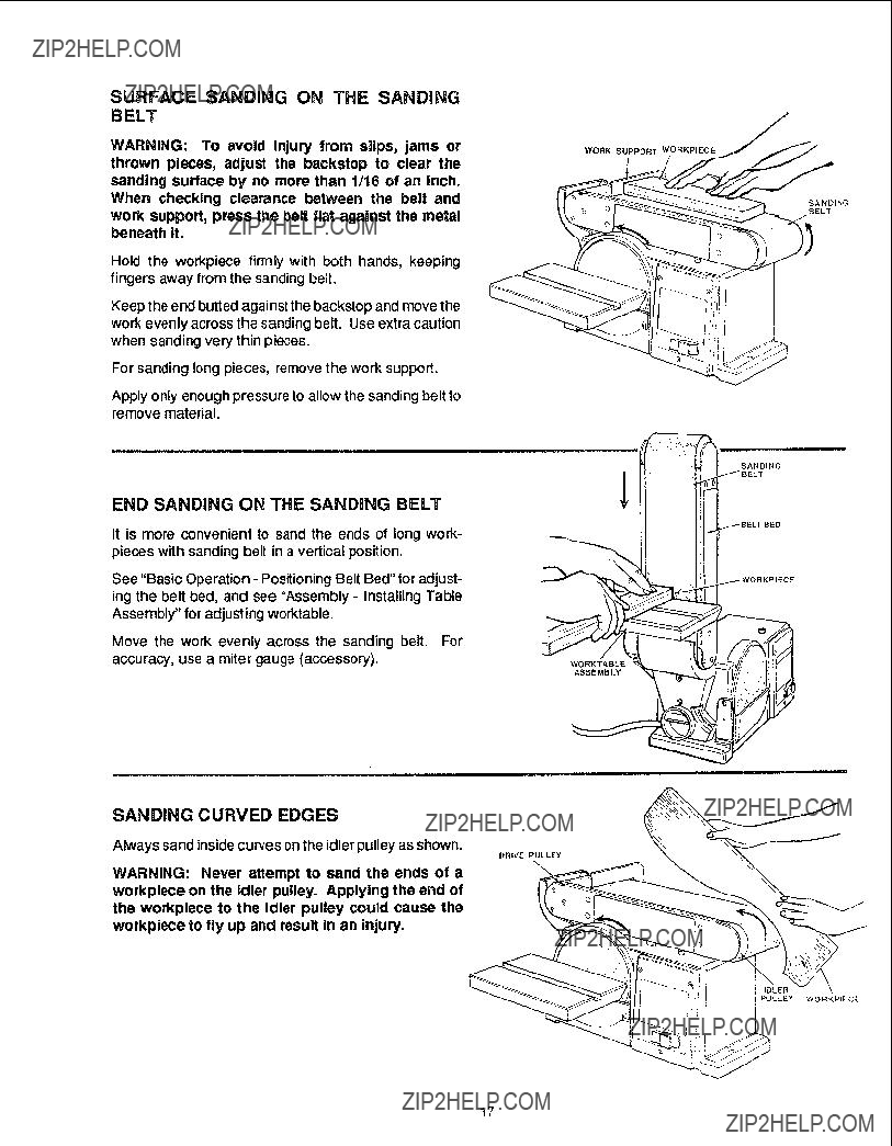
???Adjust any work support to clear the sanding surface by no more than 1/16 of an inch. When checking clearance between the belt and work support, press the belt flat against the metal beneath it.

Make sure all clamps and locks are tight and no parts have excessive play.

KEEP WORK AREA CLEAN. Cluttered areas and benches invite accidents. Floor must not be slippery.

To avoid burns or other fire damage, never use the sander near flammable liquids, vapors or gases.

PLAN AHEAD TO PROTECT YOUR EYES,

HANDS, FACE, EARS.

KNOW YOUR SANDER. Read and understand the owner's manual and labels affixed 1othe tool. Learn its application and limitations as well as the specific poten- tial hazards peculiar to this tool.

To avoid injury from accidental contact with moving parts:

KEEP GUARDS IN PLACE and in working order.

Don't do layout, assembly, or setup work on the sander while any paris are moving.

AVOID ACCIDENTAL STARTING. Make sure switch is "OFF" before plugging sander into a power outlet.

Plan your work.

USE THE RIGHT TOOL. Don'tforce tool or attachment to do a job it was not designed to do.

CAUTION: This machine is not designed for heavy deburring operations. When finishing metals, sparks or hot fragments could cause a fire. To avoid this:

o Disconnect any dust collecting hose from the sander.

???Remove all traces of wood dust from inside the sander.

???Remove all traces of metal dust from inside the sander before sanding wood again.

Dress for safety.

Any power sander can throw foreign objects into the eyes. This can cause permanent eye damage. Wear safety goggles (not glasses) that comply with ANSI Z87.1 (shown on package). Everyday eyeglasses have only impact resistant lenses. They are not safety glasses. Safety goggles are available at Sears retail catalog stores. Glasses or goggles not in compliance with ANS! Z87.1 could seriously hurt you when they break.

oDo not wear loose clothing, gloves, neckties or jew- elry (rings, wrist watches). They can get caught and draw you into moving parts.

3

safety instructions for

???Wear nonslip footwear.

???Noise levels vary widely. To avoid possible headng

damage, wear ear plugs or muffs when using sander for hours at a time.

-Sanding operations are usually dusty. Wear a dust mask along with the safety goggles.

Inspect your workplece

Make sure there are no nails or foreign objects in the part of the workpiece to be sanded.

Plan your work to avoid THROWBACKS - when the workplece catches on the sanding belt or disc and Is torn from your hands.

???Make sure there'sno debris between the workpiece and its supports.

???When sanding irregularly shaped workpieces, plan yourwork support so it will not slip and be pulled from your hands.

Use extra caution with large, very small or awkward workpieces.

Never use this tool to finish piecestoo small to hold by hand.

Use extra supports (tables, saw horses, blocks, etc.) for any workpieces large enough to tip when not held down to the table top.

NEVER use another person as a substitutefor atable extension, or as additional support for a workplece that is longer or wider than the basic sander table, or to help feed, support or pull the workpiece.

When finishing on the disc, always press the work- piece against the "Down" side of the disc. Sanding against the side coming up from under the table could damage the work by making it "chatter," or tear the work from your hands and throw it.

Sand only one workpiece at a time.

Clear everything except the workpiece and related

support devices offthe table before turning the sander

OR.

belt and disc sander

Plan the way you will hold the workpiece from start to finish.

Avoid awkward operations and hand positions where a sudden slip could cause fingers or hand to move into a sanding surface, Keepfingers away fromwherethe belt goes into the dust trap.

DON'T OVE RREAGH. Keep good footing and balance.

Keep your face and body to one side. out of line with a possible throwback.

WHENEVER SANDER iS RUNNING

WARNING: Don't let familiarity (gained from fre-

quent use of your belt and disc sander) cause a careless mistake. Acareless fraction of a second is

enough to cause a severe Injury.

Before starting yourwork, watch the sanderwhile it runs. If it makes an unfamiliar noise or vibrates a lot, stop

immediately. Tum the sander off. Unplug the sander. Do not restart until finding and correcting the problem,

Make sure the sanding disc turns counterclockwise before using the sander.

KEEP CHILDREN AWAY. Keep all visitors a safe distance from the sander. Make sure bystanders are clear of the sander and workpiece.

DON'T FORCE TOOL It will do the job better and safer at its designed rate. Press the workpiece against the sanding material only hard enough to let it sand without bogging down or binding.

Before freeing any jammed material:

o Turn switch '_FF."

Unplug the sander.

-Wait for all moving parts to stop.

BEFORE LEAVING THE SANDER:

NEVER LEAVE TOOL F_UNNING UNATTENDED. TURN POWER OFF Don't leave tool until it comes to a complete stop.

MAKE WOF_KSHOP CHILD-PROOF. Lock the shop. Disconnect master switches. Remove t heyellow switch key. Store i1away from children and others not qualified to use the tool.

motor specifications and electrical requirements

This machine is designed to use, and is equipped with, a3450 RPM motor. It is wired foroperation on 120 volts, 60 Hz., alternating current.

WARNING: To avoid electrocution or fire, tool must not be converted to operate on 240 volts.

For replacement motor, refer to parts list in this manual.

CONNECTING TO POWER SUPPLY

OUTLET

This machine must be grounded while in use to protect the operator from electric shock.

In the event of a maffunction or breakdown, grounding provides a path of least resistance for electric current to reduce the risk of electric shock.

Plug power cord into a 120V properly grounded type outlet protected by a 15 amp fuse or circuit breaker.

WARNING: To avoid electrocution: Do not let fin- gers touch the terminals of plugs when Installing or removing the plug to or from the outlet.

WARNING: If not properly grounded, this power tool can cause an electrical shock, particularly when used in damp locations close to plumbing. If an electrical shock occurs there is the potential of a secondary hazard, such as your hands contacting the sanding surface.

WARNING: To avoid electrocution or fire, if power cord Is worn or cut, or damaged in any way, have it replaced Immediately.

grounded in accordance with all local codes and erdi- nanaces.

WARNING: To avoid electrecution, if the outlet you are planning to use for this power tool Is of the two

prong type, DO NOT REMOVE OR ALTER THE

GROUNDING PRONG iN ANY MANNER. Use an adapter as shown beiow and always connect the grounding lug to a known ground.

It is recommended that you have a qualified electrician replace the TWO prong outlet with a properly grounded THREE prong outlet.

.PRONG

RECEPTACLE

ADAPTER

An adapter, as illustrated, is available for connecting plugs to 2-prong receptacles.

WARNING: The green grounding lug extending from the adapter must be connected to a permanent

ground such as to a properly grounded outlet box. Not all outlet boxes are properly grounded.

Yourunitis foruseon 120 vo_ts,and has aplugthat looks

If the grounding inst_ctions are not completely under-

stood or if you are not sure that your tool or outlet box is properly grounded, check with a qualified electrician.

_RO_NDING

pRONG

pROPERLY

_OUf{DE_

3.p RONG ou3r L_T

This power tool is equipped with a 3-conductor cord and grounding type plug listed by Underwriters' Laborato- ries. The ground conductor has a green jacket and is attached to thetool housing atone end and to the ground prong in the attachment plug at the other end, It repair or replacement of the electric cord or plug is necessary, do not connect the equipment grounding conductor to a live terminal.

This plug requires a mating 3-conductor grounding type outlet as shown. This outlet must be installed and

NOTE: The adapter i_lustrated is for use only if you already have a properly grounded 2-prong receptacle.

The use of any extension cord will cause some loss of power. To keep this to a minimum and to prevent overheating and motor burn-out, use the table below to

determine the minimum wire size (A.W.G.) extension cord.

Use only 3 wire exter_sion cords which have 3-prong grounding type plugs and 3-prong receptacles which accept the tool'splug.

_OMMWRENCH

COMBINATION SQUARE

BOARD ALONG THIS EDGE _

f

SHOULD BE NO GAP OR (3VERLAP

HERE WHEN SQUARE IS FLIPPED

OVER IN DOT'(lED POSITION,

H

Model 113.22643 Belt and Disc Sander is shipped

complete in one carton.

NOTE: Make certain all items are accounted for, before discarding any packing material.

WARNING: To avoid injury, if any parts are missing, do not attempt to assemblethe Belt and Disc Sander, plug In the power cord, or turn the switch on untilthe missing parts are obtained and installed correctly.

WARNING: Foryourownsafety, neverconnect plug to power source outlet, or insert switch key until all assembly steps are complete and until you have read and understood the entire owners manual,

6

assembJy

MOUNTING BELT AND DISC SANDER

TO WORKBENCH

If belt and disc sander is to be used in a permanent location, itshould be fastened securely to afirm support- ing surface such as a workbench,

If mounting to a workbench, holes should be drilled

through supporting surface of the workbench using dimensions illustrated.

1.The u nit should be bolted securely using 5/16" screws and hex nuts (not included). Screw length should be 1-1/2" plus the thickness of the bench top.

2.Locate and markthe holeswhere belt and disc sander is to be mounted.

3.Drill (2) 3/8" diameter holes through workbench.

4.Place belt and disc sander on workbench aligning holes on base with holes drilled in workbench.

5.Insert two 5/16" screws and tighten hex nuts.

An alternate method of mounting is to fasten belt and disc sander to a mounting board. The board should be of sufficient size to avoid tipping of sander while in use. Any good grade of plywood or chipbeard with a 3/4" minimum thickness is recommended. (Thinner chip- board can break.)

CAUTION: To avoid injury from tool movement, use 5/16" or larger screws and nuts.

1.Follow instructions for mounting to workbench, sub- stituting a board 18" x 24" minimum size and using 5/16 inch flat head screws, Iockwashers, and hex nuts (not included). Screw length should be 1-1/2" plus the thickness of the mounting board.

NOTE: For proper stability, holes must be counter sunk so screw heads are flush with the bottom surface of supporting board.

CAUTION: To avoid injury from tool movement, supporting surface where belt and disc sander is mounted should be examined carefully after mount- ing to insure that no movement during use can result. If any tipping or walking Is noted, secure

workbench or supporting surface before operating belt and disc sander.

9/16

ALL MEASUREMENTS ARE INCHES UNLESS OTHERWISE NOTED.

MOUNTING

HOLE

G

HOLE

CLAMPING BELT AND DiSC SANDER

TO WORKBENCH

The belt and disc sander can be clamped directly to a workbench using two (2) or more "C" clamps on base of unit (one clamp on each end of unit).

assembly

INSTALLING SANDING DiSC AND GUARD

1.Locate sanding disc and pee backing from disc. Align perimeter of disc with I_late and press disc firmly into position all the way around.

2.Locate disc guard and two pan head screws, M4,2 x 1.4-12 from loose Darts bag.

3.Position disc guard against lower 1/3 of disc aligning holes as shown.

4.Using phillips type screwdriver, fasten the pan head screws securely applying slight pressure to thread the holes.

INSTALLING WORK SUPPORT

1.Locate work support and hex screw M6 x 1,0-14, washer and Iockwasher.

2.Hold work support into position and fasten as shown. Do not overtighten.

INSTALLING TABLE ASSEMBLY

1.Locate table support and (3) hex head screws, M6 x 1.0-14. washer and Iockwashers among loose parts.

2.Position table support against table, aligning holes as shown.

3.Fasten table support to table as shown.

SANDING

PLATE

SANDING

DiSC

WORK SUPPOR]

TABLE

SUPPORT

///

4.Locatewasher 6.5 x 17.8 x 1.6 and knob among loose pads,

5.Position table support in corresponding holes on side of base as shown. Make sure the 9.5ram diameter index pin aligns with upper hole,

6, Place washer on threaded shaft of knob and insert through slot into threaded holes of base

SUPPORT

WARNING: To avoid trapping the work or fingers between the table and sanding surface, the table edge should be a maximum of 1/16 inch from sand- ing surface.

7, Loosen the (3) hex head screws and adjust table.

f@

li161NCH MAXIMUM

SURFACE

TABLE

8.Use your Owner's Manual as a spacer. Place ten pages of the Owner's Manual between the Disc and the front edge of the table. Hold the table against the

manual and tighten the three (3) Hex Washer Head screws.

f

SCALE LABEL TABLE LOCK

KNOB

9

assembly

AUXILIARY MOUNTING FOR VERTICAL

SANDING

1.Remove backstoplock bolt and removework support.

2.Removetable assembly by removingtable lock knob and washer.

NOTE: Beitbed may be raised to vertical position by loosening he?? socket screw and raising bed. See "PositioningBelt Bed" on page 16.

3.Attach table assembly to auxiliary holes in belt bed. Make sure index pin is in the upper hole when sanding table is in the vertical position.

SQUARING TABLE ASSEMBLY

WARNING: To avoid tnjury from accidental start, make sure tool Is unplugged before aligning.

1Using a combination square, check the angle of the worktable with the disc.

NOTE: The combination square must be "true"- See "Unpacking - Tools Needed" section on page 6 for checking method.

2.If the table is not 90?? with the disc, loosen table lock knob screw and tilt table.

3.Adjust worktable square to the disc and retighten table lock knob.

4.Attach scale mabelto 0?? mark on dust guard.

INSTALLING THE SANDING BELT -

TENSIONING AND TRACKING

WARNING: To avoid injury from accidental start, turn switch "OFF", remove key and remove plug {tom power source outlet before removing or install- ing sanding belt. To avoid injury from belt failure, use only Sears recommended sanding belts. See Sears catalog.

On the smooth side of the sanding belt, you will find a "directional arrow." The sanding belt must run in the direction of this arrow so that the splice does not come apart.

1.Slide tension lever to the right to release the belt tension.

2.Place the sanding belt over the pulleys with the directi0na arrow pointing as shown. Make sure the

:belt is Centered on both pulleys.

J

f

AUXILIARY <

MOUNTING HOLES

BACKSTOP REMOVED

COMBINATION

SQUARE

SCALE LABEL TABLE LOCK

KNOB

IDLER

PULLEY

TENSION

LEVER

DIRECTIONAL

ARROWBANDING

BELT

DRIVE

PULLEY

BED LOCKING

HEX SOCKE

SCREW

10

3.Slide tension lever to the left to apply belt tension.

4.Tighten hex socket screw when bed is in desired position.

5.Plug in the power cord. Turn switch "ON" and imme- diately "OFF," noting if the belt tends to slide off the idler pulley or drive pulley. If it did not tend tOslide off, it is TRACKING properly.

6.If the sanding belt moves toward the disc, turn the tracking knob clockwise 1/4 turn.

7.If the sanding belt moves away from the disc, turn the tracking knob counterclockwise 1/4 turn.

8.Turn switch "ON" and immediately "OFF" again, not- ing belt movement. Readjust tracking knob if neces- sary.

TENSION

LEVER

TRACKING

KNO_

!I

HOLE

1

WORK SUPPORT

SANDING

BELT

SANDING

PLATE

SANDING

DISC

/

WORKTABLE

ASSEMBLY

DISC

GUARD

7

ON-OFFMOUNTING

SWITCHHOLE

WARNING: To avold injury from accidental start, turn switch "OFF" and remove plug from power source outlet before making any adjustments.

1.Work Support. Supports the workpiece on the sand- ing belt.

2.Hex Socket Head Screw. Loosening screw allows belt bed to be raised to the vertical position.

3.Tracking Knob: Turning knob counterclockwise causes sanding beit to move towardsthe disc;turning

knob ???lockwise causes sanding belt to move away

4.Tension Lever. Sliding lever to the right releases the

sanding beit tension: sliding lever to the left applies belt tension.

5.Table Lock Knob. Loosening knob allows the work- table to be tilted for bevel sanding. (Scale pointer on table trunnion; scale attached to base.)

6.Auxiliary Mounting Hole. Allows table assembly to be mounted for end sanding when the bed is placed in vertical position.

7.On-Off Switch.

12

ON-OFF SWITCH

The On-Off switch has a locking feature. THIS FEA-

TURE IS INTENDED TO HELP PREVENT UNAUTHOR-

IZED AND POSSIBLY HAZARDOUS USE BY CHIL-

DREN AND OTHERS.

1. To turn machine "ON" insert key into switch.

NOTE: Key is made of yellow plastic, located in loose parts bag,

2.Insert finger under switch lever and PULL end of switch out.

3. To turn machine "OFF".. PUSH lever in.

NEVER LEAVE THE MACHINE U NATrENDED UNTIL

IT HAS COME TO A COMPLETE STOP.

4.To lock switch in OFF position.., hold switch IN with one hand... REMOVE key with other hand.

WARNING: For your own safety, always lock the switch "OFF" when machine is not in use.., remove key and keep it in a safe place.., also.., in the event of a power failure (all of your lights go out) turn switch off.., remove the key and store it remote from belt and disc sander.

13

BEFORE USING THE SANDER

WARNING: To avoid mistakes that could cause serious, permanent injury, do not plug the sander in untU the following steps are comp|eted.

-Assembly and alignment. (See pages 7 - 11 }

=Learn the use and function of the ON-OFF switch. backstop, belt tracking knob, belt tension lever, work table and work table tilt lock knob. (Seepages t2-13)

Review and understand all safety instructions and operating procedures in this manual.

Review of the maintenance methods for this sander. (See pages 19 - 20)

BEFORE EACH USE:

Inspect your sander.

DISCONNECT THE SANDER. To avoid injury from accidental starting, unplug the sander,turn the switch off and remove the switch key before changing the setup, sanding disc or belt or adjusting anything.

CHECK DAMAGED PARTS. Check for:

. alignment of moving parts,

-binding of moving pads,

???broken parts,

???wom parts that cause a gap largerthan 1/16" between work support and sanding surface,

sanding belt narrowerthan 4 inches. Narrower belts uncover parts that could trap your fingers.

-worn or damaged elect tic cords, stable mounting, and

any other conditions that may affect the way the sander works.

If any part is missing, bent, or broken in any way, or any electrical parts don'twork properly, turn the sander off and unplug the sander. REPLACE damaged, missing, or failed parts before using the sander again.

MAINTAIN TOOLS WITH CARE.

Keep the sander clean for best and safest performance. Follow instructions for lubricating.

REMOVE ADJUSTING KEYS AND WRENCHES from tool before turning it on.

To avoid Injury from jams, slips or thrown pieces.

USEONLY RECOMMENDEDACCESSORIES. (See

page 21) Consult this Owner's manual for recom- mended accessories. Follow the instnJctions that come with the accessories. The use of improper accessories may cause risk of injuryto persons.

Adjust any work support to clear the sanding surface by no more than 1/16 of an inch. When checking clearance between the belt and work support, press the belt flat against the metal beneath it.

-Make sure all clamps and locks are tight and no Parts have excessive play.

KEEP WORK AREA CI'EAN. Cluttered areas and benches invite accidents. Floor must not be slippery.

To avoid bums or other fire damage, never use the sander near flammable liquids, vapors or gases.

PLAN AHEAD TO PROTECT YOUR EYES,

HANDS, FACE, EARS

KNOW YOUR SANDER. Read and understand the owner's manual and labels affixed to the tool. Learn its application and limitations as well as the specific poten- tial hazards peculiar to this tool.

To avoid injury from accidental contact with moving parts:

-KEEP GUARDS IN PLACE and in working order.

-Don't do layout, assembly, or setup work on the sander while any parts are moving.

-AVOID ACCIDENTAL STARTING. Make sure switch is "OFF" before plugging sander into a power outlet.

Plan your work.

USETHE RIGHTTOOL. Don'tforce tool or attachment

to do a job it was not designed to do.

CAUTION: This machine Is not designed for heavy deburrlng operations. When finishing metals, sparks or hot fragments could cause a fire. To avoid this:

Disconnect any dust collecting hose from the sander.

??Remove all traces of wood dust from inside the sander.

???Remove all traces of metal dust from inside the sander before sanding wood again.

14

Dressfor safety,

Any power sander can throw foreign objects into the eyes. This can cause permanent eye damage. Wear safety goggles (not glasses) that comply with ANSI Z87.1 (shown on package). Everyday eyeglasses have only impact resistant lenses. They are not safety glasses. Safety goggles are available at Sears retail catalog stores. Glasses or goggles not in compliance with ANSI Z87.1 could seriously hurt you when they break.

???Do not wear loose clothing, gloves, neckties or jew- elry (rings, wrist watches). They can get caught and draw you into moving parts.

???Wear nonslip footwear. Tie back long hair.

Roll long sleeves above the elbow.

???Noise levels vary widely. To avoid possible hearing

damage, wear ear plugs or muffs when using sander for hours at a time.

Sanding operations are usually dusty. Wear a dust mask along with the safety goggles.

Inspect your workpiece

Make sure there are no nails or foreign objects in the part of the workpiece to be sanded.

Plan your work to avoid THROWBACKS - when the workpiece catches on the sanding belt or disc and is torn from your hands.

Make sure there'sno debris between the workpiece and its supports.

When sanding irregularly shaped workpieces, plan

your work support so it will not sitp and be pulled from your hands.

Use extra caution with large, very small or awkward workpieces.

Never use this tool to finish pieces too small to hold by hand.

Use extra supports (tables, saw horses, blocks, etc.) for any workpieces large enough to tip when not held down to the table top.

NEVER use another person as a substitute for atable extension, or as additional support for a workpiece that JsIonger or wider than the basic sander table, or to help feed, support, or pull the workpiece.

When finishing on the disc, always pressthe workpiece against the "Down" side of the disc. Sanding against the side coming up from under the table could dam- age the work by making it "chatter," or tear the work from your hands and throw it.

Sand only one workpiece at a time.

Clear everything except the workpiece and related support devices off the table before turning the sander

on.

Plan the way you will hold the workplece from start to finish.

Avoid awkward operations and hand positions where a sudden slip could cause fingers or hand to move into a sanding sudace. Keep fingers away from where the belt goes into the dust trap.

DON'TOVERREACH. Keep good footing and balance.

Keep your face and body to one side, out of line with a possible throwback.

WHENEVER SANDER IS RUNNING

WARNING: Don't Jet familiarity (gained from fre-

quent use of your belt and disc sander) cause a careless mistake. A careless fraction of a second is

enough to cause a severe injury.

Before starting you r work, watch the sanderwhi]e it runs. If it makes an unfamiliar noise or vibrates a lot, stop immediately. Turn the sander off. Unplug the sander. Do not restart until finding and correcting the problem.

Make sure the sanding disc turns counterclockwise before using the sander.

KEEP CHILDREN AWAY. Keep all visitors a safe distance from the sander. Make sure bystanders are clear of the sander and workpiece.

DON'T FORCE TOOL. it will do the job better and safer at its designed rate. Press the workpiece against the sanding material only hard enough to let it sand without bOgging down or binding.

Before freeing any jammed material:

???Turn switch "OFF." Unplug the sander.

???Wait for all moving parts to stop.

BEFORE LEAVING THE SANDER:

NEVER LEAVE TOOL RUNNING UNATTENDED. TURN POWER OFF. Don'tleave tool until it comes to

a complete stop.

MAKE WORKSHOP CHILD-PROOF. Lock the shop. Disconnect master switches. Remove the yellow switch

key. Store it away from children and others net qualified to use the tool.

15

basic operation

BEVEL SANDING

The worktable can be tilted from 0oto 45 ?? for bevel sanding. Loosen the table lock knob and tilt the work- table to desired angle as shown. Retighten table lock

Knob.

WARNING: TO avoid trapping the work or fingers between the table and sanding surface, the table should be reposltioned on the table support to retain

a maximum of 1/16 Inch distance between sanding surface and table.

POSITIONING BELT BED

A bed locking hex socket head screw locks the belt bed in a vertical or horizontal position.

To adjust vertical position:

1.Remove the work support.

2.Loosen the hex socket head locking screw using a 6mm hex wrench.

3.Position belt bed vertically as shown and tighten the hex socket head screw.

TABLE

,WORK SUPPORT

HEX SOCKET

SCREW

_HEX"L" WRENCH

16

SURFACE SANDING ON THE SANDING

BELT

WARNING: To avoid injury from sflps, jams or thrown pieces, adjust the backstop to clear the sanding surface by no more than 1/16 of an inch. When checking clearance between the belt and work support, press the belt flat against the metal beneath it.

Hold the workpiece firmly with both hands, keeping fingers away from the sanding belt.

Keep the end butted against the backstop and move the work evenly across the sanding belt. Use extra caution when sanding very thin pieces.

For sanding long pieces, remove the work support.

Apply only enough pressure to allow the sanding belt to remove material.

END SANDING ON THE SANDING BELT

It is more convenient to sand the ends of long work- pieces with sanding belt in a vertical position.

See "Basic Operation - Positioning Belt Bed" for adjust- ing the belt bed, and see "Assembly - Installing Table Assembly" for adjusting worktable.

Move the work evenly across the sanding belt. For accuracy, use a miter gauge (accessory).

WORK SUPPORT WORKPIECE

SANDING

BELT

SANDING

WORKTABLE

ASSEMBLY

SANDING CURVED EDGES

Always sand inside curves on the idler pulley as shown.

DRIVE PULLEY

WARNING: Never attempt to sand the ends of a workpiece on the Idler pulley. Applying the end of the workpiece to the idler pulley could cause the workpiece to fly up and result In an injury.

PULLEY WORKPIEC??

17

basic operation

Always sand outside curves on the left side ofcenter on the sanding disc as shown.

WARNING: Applying the workplece to the right side of the disc could cause workplece to fly up (kick- back) and result In an Injury.

SANDING SMALL END SURFACES ON

THE SANDING DISC

NOTE: Use of a Miter Gauge (optional accessory) is recommended for this operation.

Always move the work across left side of center on the sanding disc face as shown,

WARNING: Applying the workpiece to the right side of the disc first could cause workplece to fly up (kickback) and result In an Injury.

WARNING: For yourown safety, turn switch"OFF" and remove plug from pOwer source outlet before aajustlng your sander.

NOTE: Use a combination square to square the miter gauge to the face of the disc (combination _uare must be "true" - See "Unpacking - Tools Needed" section on page 6 for checking this rnethod). If it is not square, loosen the miter gauge knob and move the miter gauge slightly until it is square. Without moving the miter gauge, tighten the knob securely,

Always position the workpiece to the left of center on

sanding disc with disc rotating counterclockwise as shown,

The table may be tilted for beveled work.

WORKPIECE

SANDING

DISC

MITER GAUGE

ACCESSORYI

\

\

WORKPIECE

CENTER

MITER GAUGE

,ACCESSORY

COMBINATION

SQUARE

\

\

(LEN OF CENTER)

18

maintenance

WARNING: For your own safety, turn switch "OFF" and remove plug from power source outlet before adjuSting, maintaining, or lubrlcsting your belt and disc sander.

WARNING: TO avoid electrocution or fire, any re- pairs to electrical systems should be done only by qualified service technicians. Unit must be reas- sembled exactly to factory specifications.

Ifpowercord is worn orcut, ordamaged in anyway, have it replaced immediately.

Frequently blow out or vacuum out any dust that may accumulate inside the motor.

A coat of automobile-type wax applied to the worktable will make it easier to feed the work while finishing.

Do not apply wax to the abrasive belt table because the belt could pick up the wax and deposit it on the pulleys, causing the belt to slip.

LUBRICATION

The BALL BEARINGS in this machine are packed with grease at the factory. They require no further lubrication. Sleeve bearings should be lubricated with 30 weight oil or equivalent after each 10 hours of operation.

REMOVING PULLEY COVER AND

INSTALLING DRIVE BELT

1.Using a phillips screwdriver, remove the flat head screw located in the middle of the cover.

2.Remove the cover.

3.Loosen (3) screws to allow pulleys to shift enough to place belt around them. Place belt around motor pulley and d rive pulley as shown if belt is ever broken.

WIRING DIAGRAM

PULLEY

COVER

PHILLIPS

SCREWDRIVER

BELT

MOTOR

PULLEY

SCREWS

19

maintenance

4.Slightly tighten (3) screws. Adjust tension of belt by

putting blade screwdriver in adjusting hole. Push up on screwdriver to tighten tension between pulleys.

5 Tighten screws being careful not to disturb belt.

STANDARD

SCREWDRIVER

\

ADJUSTING

HOLE

6.Test belt tension by placing fingers on either side of belt and squeeze. There should be about a 1/4" give to the belt.

NOTE: Excessive tightness on pulley belt may cause increased noise and over load motor. Excessive loose-

ness on pulley belt may cause belt to fail prematurely.

BELT

INSTALLING PULLEY COVER

1. Locate the pulley cover and position it inside the relief edges of pulley housing.

2. Using a phillips screwdriver, reinstall and tighten the flat head screw.

=ULLEY

COVER

2O

troubleshooting

WARNING: For your own safety, turn switch "OFF" and remove plug from power source outlet before troubleshooting your sander.

Motor will not run. 1. Defective On-Off switch Defective switch cord. Defective switch box.

2. Burned out motor.

REMEDY

1.Replace defective parts before using belt disc sander again.

2.Consult Sears Service. Any attempt to repair this motor may create a HAZARD unless repair is done by a qualified service technician. Repair service is available at your nearest Sears Store.

1.Decrease belt tension, see Maintenance section, "Removing Pulley Cover and Installing Timing Belt."

2.Ease up on pressure.

1.Adjust tracking, see Assembly section, "installing the Sanding Belt - Tensioning and Tracking"

1. Replace disc or belt.

1.Decrease belt tension, see Maintenance Section "Removing Pulley Cover and Installing Timing Belt".

sears recommends the following

accessories

Sears may recommend other accessories not listed in the manual. See your nearest Sears store or Catalog department for other accessories.

Do not use any accessory unless you have received and read complete instructions for its use.

21

repair parts

o

\

!

/

22

repair parts

PARTS LiST FOR CRAFTSMAN BELT AND DiSC SANDER

MODEL 113.226430

Standard Hardware Item - May be purchased locally.

tStock Item - May be secured through the Hardware

Department of most Sears Retail Stores and Catalog Order Houses.

??Relay must accompany motor when motor is returned for service. Any attempt to repair this motor may

48STD851006 * Washer, M6 x 12 x 1.6

49820242 ,_, Ring, Retaining M12

create a hazard unless repair is done by a qualified

service technician. Repair service is available at your nearest Sears store.

,& WARNING: These Items Are Important To The

Safety Of This Tool. DO Not Substitute Common

Parts.

23

SERVICE

MODEL NO. 113.226430

HOW TO ORDER

REPAIR PARTS

BELTAND DISC

SANDER

Now that you have purchased your Belt and Disc Sander, should a need ever exist for repair parts or service, simply contact any Sears Service Center and most Sears, Roebuck and Co. stores. Be sure to provide all pertinent facts when you call or visit.

The model number of your Belt and Disc Sander will

be found on a plate attached to your sander on the back side of the base.

WH EN ORDERING REPAIR PARTS, ALWAYS GIVE

THE FOLLOWING INFORMATION:

All parts listed may be ordered from any Sears Service Center and most Sears stores. If the parts you need are not stocked locally,your orderwill be electronically transmitted to a Sears Repair Parts Distribution Cen- ter for handling.

Sold by SEARS, ROEBUCK AND CO., Chicago, IL 60684 U.S.A.