....
917.256500 OWNER'S MANUAL
oAssembly Operation
Customer Responsibilities Service and Adjustments Repair Parts
[]
....
917.256500 OWNER'S MANUAL
oAssembly Operation
Customer Responsibilities Service and Adjustments Repair Parts
[]

&SAFETY RULES
Safe Operation Practices for
iMPORTANT: THiS CUTTING MACHINE tS CAPABLE OF AMPUTATING HANDS AND FEET AND THROWING OBJECTS. FAILURE TO OBSERVE THE FOLLOWING SAFETY INSTRUCTIONS COULD RESULT iN SERIOUS INJURY OR DEATH.
.... i
|. GENERAL OPERATION
??Read, understand, and foilow all instructions in the manual and on the machine before starting.
???Only allow responsible adults, who are familiar with the instructions, to operate the machine.
???Clear the area of objects such as rocks, toys, wire, etc., which could be picked up and thrown by the blade.
???Be sure the area Js clearof other people before mowing, Stop machine if anyone enters the area.
o Never carry passengers,
=Do not mow in reverse unless absolutely necessary. Always look down and behind before and while backing.
???Be aware of the mower discharge direction and do not point it at anyone. Do not operate the mower without either the entire grass catcher or the guard in place.
o Slow down before turning.
=Never leave a running machine unattended. Always turn off blades, set parking brake, stop engine, and remove keys before dismounting.
,Turn off biades when not mowing.
IlL CHILDREN
Tragic accidents can occur if the operator is not alert to the presence of children. Children are often attracted to the machine and the mowing activity. Never assume that children will remain where you last saw them.
=Keep children out of the mowing area and under the watchful care of another responsible adult.
Be alert and turn machine off if children enter the area.
*Before and when backing, look behind and down for small children.
,Never carry children. They may fall off and be seriously injured or interfere with safe machine operation.
o Never atlow children to operate the machine,
*Use extra care when approaching blind corners, shrubs, trees, or other objects that may obscure vision.
IV. SERVICE
oUse extra care in handling gasoline and other fuels, They are flammable and vapors are explosive.
???Stop engine before removing grass catcher or unclogging chute.
,Mow only Jn daylight or good artificial light.
???Do not operate the machine while under the influence of alcohol or drugs.
??Watch for traffic when operating near or crossing roadways.
oUse extra care when loading or unloading the machine into a trailer or truck.
ii.SLOPE OPERATION
Slopes are a major factor related to
DO:
??Mow up and down slopes, not across.
??Remove obstacles such as rocks, tree limbs, etc.
???Watch for holes, ruts, or bumps. Uneven terrain could overturn the machine. Tall grass can hide obstacles.
???Use slow speed. Choose a low gear so that you wil! not have to stop or shift while on the slope.
???Follow the manufacturer's recommendations for wheel weights or counterweights to improve stability.
oUse extra care with grass catchers or other attachments. These can change the stability of the machine.
oKeep a]! movement on the slopes slow and gradual. Do not make sudden changes in speed or direction.
Use only an approved container.
Never remove gas cap or add fuel with the engine
running. Allow engine to cool before refueling. Do not smoke.
Never refuel the machine indoors,
Never store the machine or fuel container inside where there is an open flame, such as a water heater.
Never run a machine inside a closed area.
Keep nuts and bolts, especially blade attachment bolts, tight and keep equipment in good condition.
Never tamper with safety devices. Check their proper operation regularly.
Keep machine free of grass, leaves, or other debris
qStop and inspect the equipment if you strike an object. Repair, if necessary, before restarting.
o Never make adjustments or repairs with the engine running.
??Grass catcher components are subject to wear, damage, and deterioration, which could expose moving parts or allow objects to be thrown. Frequently check components and replace with manufacturer's recommended parts, when nec- essary.
oMower blades are sharp and can cut. Wrap the blade(s) or wear gloves, and use extra caution when set'???icing them.
??Check brake operation frequently. Adjust and service as required.
,i
???Avoid starting or stopping on a slope, tf tires lose traction, disengage the blades and proceed slowly straight down the slope.
DO NOT:
???Do not turn on slopes unless necessary, and then, turn slowly and gradually downhill, if possible.
??Do not mow near
???Do not mow on wet grass. Reduced traction could cause sliding.
??Do not try to stabilize the machine by putting your foot on the ground.
portant safety precautions. It means LookCAUTION!!!for this BECOMEsymbol toALERT!!!point outYOURim-
SAFETY IS INVOLVED.
i i ii i
CAUTION: Always disconnect spark plug
spark plug in order to prevent accidental wireand placewire where it cannot contact starting when setting up, transporting,
adjusting or making repairs.
A WARNING & ........
2

CONGRATULATIONS on your purchase of a Sears Tractor. it has been designed, engineered and manufac- tured to give you the best possible dependability and performance.
Should you experience any problem you cannot easily remedy, please contact your nearest Sears Authorized Service Center/Department. We have competent, wel!- trained technicians and the proper tools to service or repair this tractor.
Please read and retain this manual. The instructions will
enable you to assemble and maintain your unit properly. Always observe the "SAFETY RULES".
MODEL
NUMBER 917.256500
SERIAL
NUMBER
DATE OF PU RCHASE
THE MODELAND SERIAL NUMBERSWILL BE FOUND
ON A PLATE UNDER THE SEAT.
YOU SHOULD RECORD BOTH SERIAL NUMBER AND
DATE OF PURCHASE AND KEEP IN A SAFE PLACE
FOR FUTURE REFERENCE.
MAINTENANCE AGREEMENT
A Sears Maintenance Agreement is available on this prod- uct. Contact your nearest Sears store for details.
CUSTOMER RESPONSIBIMT ES
??Read and observe the safety rules.
oFollow a regularschedule in maintaining, caring for and using your tractor.
Follow the instructions under "Customer Responsibili- ties" and "Storage" sections of this owneCs manual.
WARNING: This tractor is equipped with an internal combustion engine and should not be used on or near any unimproved
PRODUCT SPECJFmCAT ONS
with a spark arrester meeting applicable local or state laws (if any). If a spark arrester is used, it should be maintained in effective working order by the operator.
In the state of California the above is required by law (Section 4442 of the California Public Resources Code). Otherstates may have similar laws. Federal laws apply on federal lands. A spark arrester for the muffler is available through your nearest Sears Authorized Service Center/ Department (See REPAIR PARTS section of this manual).
LBM TED TWO YEAR WARRANTY ON CRAFTSMAN RMDING EQUIPMENT
For two (2) years from the date of purchase, if this Craftsman Riding Equipment is maintained, lubricated and tuned up according to the instructions in the owner's manual, Sears will repair or replace, free of charge, any parts found to be defective in materiaf or workmanship.
This Warranty does not cover:
Expendable items which become worn during norma! use, such as blades, spark plugs, air cleaners, betts, etc.
=Tire replacement or repair caused by punctures from outside objects, such as nails, thorns, stumps, or glass.
???Repairs necessary because of operator abuse, negligence, improper storage or accident or the failure to maintain the
equipment according to the instructions contained in the owner's manual. Riding equipment used for commercial or rental purposes.
LIMITED 90 DAY WARRANTY ON BATTERY
For ninety (90) days from date of purchase, if any battery included with this riding equipment proves defective in material or workmanship and our testing determines the batten/will not hold a charge, Sears will replace the batten,7at no charge.
DAYS FROM THE DATE OF PURCHASE. PLEASE CONTACT YOUR NEAREST SERVICE CENTER. AFTER 30 DAYS FROM
THE DATE OF PURCHASE, WARRANTY SERVICE IS AVAILABLE BY TAKING YOUR CRAFTSMAN RIDING EQUIPMENT TO
YOUR NEAREST SEARS SERVICE CENTER.
FROM THE DATE OF PURCHASE BUT A STANDARD TRIP CHARGE WILL APPLY.) THIS WARRANTY APPLIES ONLY
WHILE THIS PRODUCT IS IN THE TRACTORED STATES.
This Warranty gives you specific legal rights, and you may also have other rights which may vary from state to state.
SEARS, ROEBUCK AND CO., D/817 WA, HOFFMAN ESTATES, IL 60179
3

W

........ !
ACCESSORIES AN ATTACHME TS
These accessories and attachments were available th rough most Sears retait outlets and service centers when the tractor'was purchased. Most Sears stores can order these items for you when you provide the model number of your tractor.
i
PERFORMANCE
Sears offers a wide variety of attachments that fit your tractor. Many of these are listed below with brief explanations of how they can help
you. This list was current at the time of publication; however, it may change in future years - more attachments may be added, changes may be made in these attachments, or some may no longer be available or fit your model. Contact your nearest Sears store for the accessories and attachments that are available for your tractor.
Most of these attachments do not require additional hitches or conversion kits (those that do are indicated) and are designed for easy attaching and detaching.
AERATOR promotes deep root growth for a healthy lawn. Ta- pered
Steel weight tray for increased penetration.
BAGGER lets you collect grass clippings and leaves for a healthier, neuter looking lawn. Two Permanex containers hold
BUMPER protects front end of tractor from damage.
CARTS make hauling easy. Variety of sizes available, plus
accessories such as side panel kits, tool caddy, cart cover, protective mat and dolly.
CORING AERATOR takes small plugs out of sol! to allow mois- ture and nutrients to reach grass roots.
EASY OIL DRAIN VALVE makes oil changes easier, faster. FRONT NOSE ROLLER canters in front of mower deck to reduce chances of "scalping" on uneven terrain.
GANG HITCH lets you tow 2 or 3
GAUGE WHEELS on both sides of the mower deck reduce
chances of "scalping" on uneven terrain. For mower decks not so equipped.
MULCH
SPRING TINE DETHATCHER covers
MULCHING
mowers. See "MOWER" in the Repair Parts section of this manual.
RAMP TOPS AND FEET let you load and unload tractor from a pickup truck. Use with 2 x 8 or 2 x I0 lumber.
ROLLER for smoother lawn surface. 364nch wide,
edges prevent harm to turf. Adjustable scraper automatically cleans drum.
SNOW BLADE for snow removat only. t
SNOWTHROWER has
tractor seat. (Use with chains and wheel weights and/or rear drawbar weight.)
SPRAYERS use
SPREADER/SEEDERS make seeding, fertilizing, and weed kill-
ing easy. Broadcast spreaders are atso useful for granular de- icers and sand.
SWEEPERS let you collect grass clippings and leaves.
TILLER has 5 hp engine and
TIRE CHAINS are heavy duty; closely spaced
TRACTOR CAB has heavy duty vinyt fabric over tubular steel frame, ABS plastic top; clear plastic windshield offers 360 degree visibility. Hinged metal doors with catch. Keeps operator warm and dry. Remove vinyl sides and windshields for use as sun protector in summer. Optional accessories include: tinted/ tempered solid safety glass windshieJd with hand operated wiper;
VACS for powerful collection of heavy grass clippings and Ieaves. Optionat wand attachment to pick up debris in
WEIGHT BRACKET for drawbar for snow removal applications. Uses (1) 55 lb. weight.
WHEEL WEIGHTS for rear wheels provide needed traction for snow removal or dozing heavy materials.

Parts Bag contents shown full size
...... i
(2) Sheet
Metal
O Screws
#1046 x 1/2
(1) Locknut
(1) Large Flat Washer
|I I
(t) Hex Bolt
(1) Shoulder Bolt
(1) Lock Washer I/2
(t)Washer 17/32
x
@
(2) Hex Bolts
(2) Hex Nuts
(2) Lock Washers 1/4
(2) Washers 9/32 x 5/8 x t6 Gauge
Parts packed separately in carton
Seat
Parts bag contents not shown full size
Slope Sheet
6
.......... i
ASSEM LY
Your new tractor has been assembled at the factory with exception of those parts left unassembled for shipping purposes. To ensure safe and proper operation of your tractor all parts and hardware you assemble must be tightened securely. Use the correct tools as necessary to insure proper tightness.
TOOLS REQUIRED FOR ASSEMBLY
A socket wrench set wit] make assembly easier, Standard wrench sizes are listed.
When right or left hand is mentioned in this manual, it means when you are in the operating position (seated behind the steering wheel).
TO REMOVE TRACTOR FROM CARTON
UNPACK CARTON
oRemove all accessible loose parts and parts cartons from carton (See page 6).
oCut, from top to bottom, along lines on all four corners of car_on, and lay panels flat.
???Check for any additional loose parts or cartons and remove.
BEFORE ROLUNG TRACTOR OFF SKID
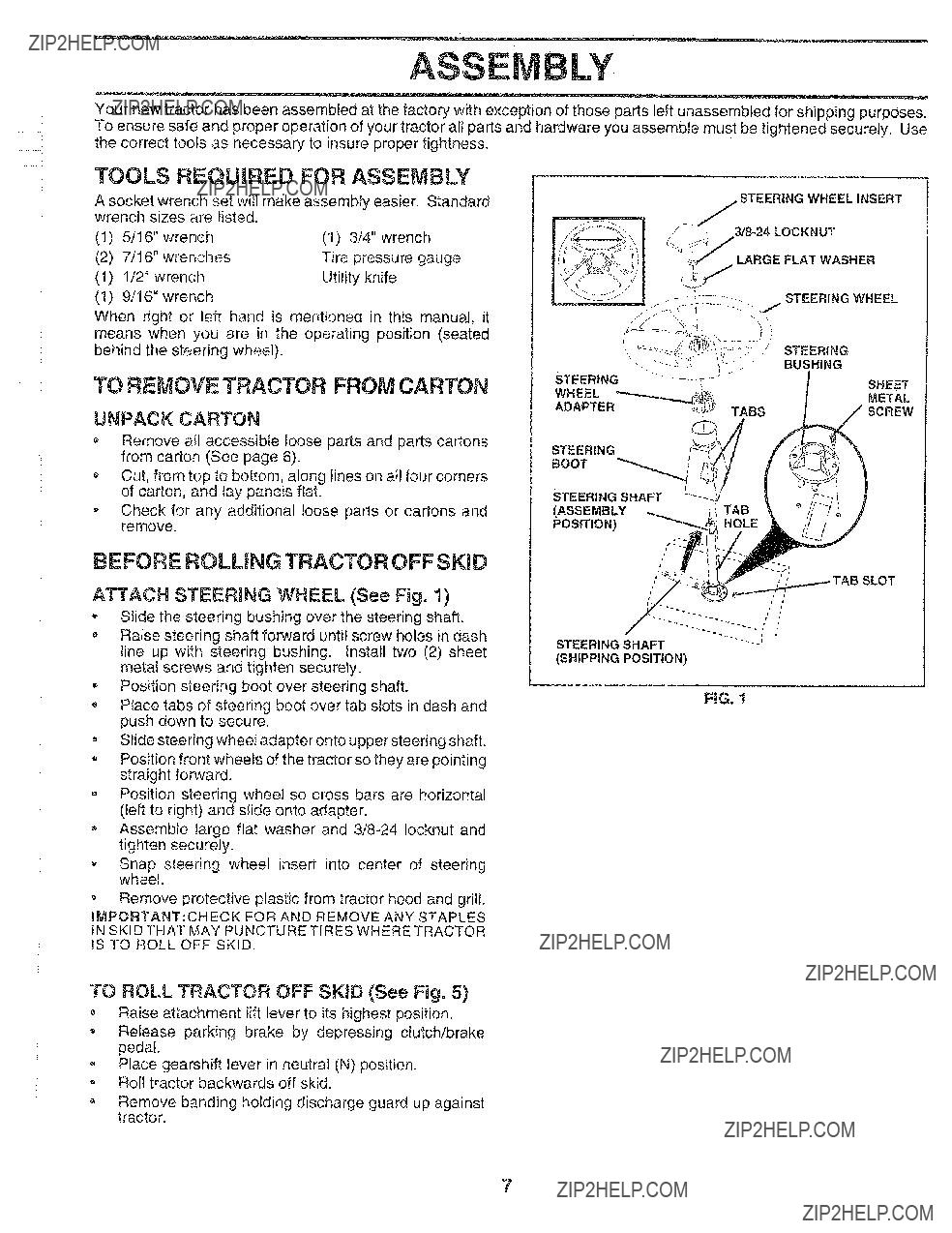
ATTACH STEERING WHEEL (See Fig. 1)
-Slide the steering bushing over the steering shaft.
,Raise steering shaft forward until screw holes in dash line up with steering bushing. Install two (2) sheet metal screws and tighten securely.
*Position steering boot over steering shaft.
Ptace tabs of steering boot over tab slots in dash and push down to secure.
o Slide steering wheel adapter onto upper steering shaft.
oPosition front wheels of the tractor so they are pointing straight forward.
Position steering wheel so cross bars are horizontal (left to right) and slide onto adapter.
oAssemble large flat washer and
,Snap steering wheel insert into center of steering wheel.
o Remove protective plastic from tractor hood and grill.
WMPORTANT:CHECK FOR AND REMOVE ANY STAPLES
IN SKID THAT MAY PUNCTURE TIRES WHERE TRACTOR
IS TO ROLL OFF SKID.
STEERING SHAFT
(SHIPPING POSITION)
FIG, 1
TO ROLL TRACTOR OFF SKiD (See Fig. 5)
???Raise attachment lift lever to its highest position.
Release parking brake by depressing clutch/brake pedal.
Place gearshift lever in neutral (N) position, o Roll tractor backwards off skid.
oRemove banding holding discharge guard up against tractor.
7

ASSE BLY
...... i
CONNECT BATTERY (See Figs, 2 and 3)
CAUTION: Do not short battery tern}i, rials. Before connecting battery, re- move n}etai bracelets, wristwatch bands, rings, etc.
Positive terminal must be connected first to prevent sparking from acciden- tal grounding,
???Remove cardboard packing from seat pan and lift seat pan to raised position.
Open battery box door.
Remove terminal protective caps and discard.
,If this battery is put into service after month and year indicated on label (label located between terminals) charge battery for minimum of one hour at
???First con nect RED battery cable to positive (+) terminal with hex bolt, flat washer, lock washer and hex nut as shown. Tighten securely.
Connect BLACK grounding cable to negative
, Close battery box door.
Open battery box door for:
???Inspection for secure connections (to tighten hard- ware).
o Inspection for corrosion.
???Testing battery.
???Jumping (if required).
o Periodic charging.
DISCARD TERMINAL PROTECTIVE
CAPS
LOCK
HEX WASHER
NUT
\\ FLAT
WASHER
HE??
BOLT
NEGATIVE
(BLACK)CABLE
RG. 2
SEAT
PAN
BATTERY
BOX DOOR
FiG, 3
iNSTALL SEAT (See Fig, 4)
Adjust seat before tightening adjustment bolt.
-Remove cardboard packing on seat pan.
-Place seat on seat pan and assemble shoulder bolt.
=Assemble adjustment bolt, lock washer and flat washer loosely. Do not tighten.
???Tighten shoulder bolt securely.
Lower seat into operating position and sit on seat.
???Slide seat until a comfortable position is reached which allows you to press clutch/brake pedal all the way down.
o Get off seat without moving its adjusted position.
=Raise seat and tighten adjustment bolt securely,
SEAT
SEAT PAN
SHOULDER
BOLT
8

ASS LY
.......... i
CHECK T1RE PRESSURE
The tires on your tractor were overinflated at the factory for shipping purposes. Correct tire pressure is important for best cutting performance.
Reduce tire pressure to PSI shown in "PRODUCT SPECIFICATIONS" on page 3 of this manual.
CHECK DECK LEVELNESS
For best cutting results, mower housing should be :properly leveled. See "TO LEVEL MOWER HOUSING" in the
Service and Adjustments section of this manual.
CHECK FOR PROPER POSIT|ON OF ALL
BELTS
See the figures that are shown for replacing motion and mower blade drive belts in the Service and Adjustments section of this manual. Verify that the belts are routed correctly.
CHECK BRAKE SYSTEM
After you learn how to operate your tractor, check to see that the brake is properly adjusted. See "TO ADJUST BRAKE" in the Service and Adjustments section of this manual,
,/CHECKMST
BEFORE YOU OPERATE AND ENJOY YOUR NE_,
TRACTOR, WE WISH TO ASSURE THAT YOU RECEIVE THE BEST PERFORMANCE AND SA TISFA CTION FROth,
THIS QUALITY PRODUCT.
PLEASE REVIEW THE FOLLOWING CHECKLIST:
/AII assembly instructions have been completed.
_/ No remaining loose parts in carton.
??Battery is properly prepared and charged. (Minimum 1 hour at 6 amps).
v' Seat is adjusted comfortably and tightened securely.
v" All tires are properly inflated. (For shipping purposes, the tires were overinflated at the factory).
??" Be sure mower deck is properly leveled
,/ Check mower and drive belts. Be sure they are routed properly around pulleys and inside all belt keepers.
v" Check wiring. See that al! connections are still secure and wires are properly clamped.
WHILE LEARNING HOW TO USE YOUR TRACTOR, PAY
EXTRA A TTENT!ON TO THE FOLLOWING IMPORTANT
ITEMS:
???" Engine oil is at proper level.
,/ Fuel tank is filled with fresh, clean, regular unleaded gasoline.
v" Become familiar with all controls - their location and function. Operate them before you start the engine.
,/ Be sure brake system is in safe operating condition.
9

E
....... i
OPERATIO
These symbols may appear on your tractor or in literature supplied with the product. Learn and understand their meaning.
Z
10
OPERATION
KNOW YOUR TRACTOR
READ THIS OWNER'S MANUAL AND SAFETY RULES BEFORE OPERATING YOUR TRACTOR
Compare the illustrations with your tractor to familiarize yourself with the locations of various controls and adjustments. Save this manual for future reference.
PARKING
BRAKE
GEARSHIFT
LEVER
FIGo 5
Our tractors conform to the safety standards of the American National Standards Institute.
ATTACHMENT CLUTCH LEVER: Used to engage the
mower blades, or other attachments mounted to your tractor.
LIGHT SWITCH: Turns the headlights on and off.
THROTTLE/CHOKE CONTROL: Used for starting and controlling engine speed.
CLUTCH/BRAKE PEDAL: Used for declutching and brak- ing the tractor and starting the engine.
PARKING BRAKE: Locks clutch/brake pedal into the brake position.
GEARSHIFT LEVER: Selects the speed and direction of tractor.
ATTACHMENT LiFT LEVER: Used to raise, lower, and adjust the mower deck or other attachments mounted to your tractor.
LiFT LEVER PLUNGER: Used to release attachment lift lever when changing its position.
mGNITION SWITCH: Used for starting and stopping the engine.
AMMETER: Indicates battery charging (+) or discharging
(4.
!1

OPERA O
...... !
Theoperation of any tractor can resuJt in foreign objects thrown into the eyes, which can result in severe eye damage. Always wear safety glasses or eye shields while operating your tractor or performing any adjustments or repairs. We recommend a wide vision safety mask over the spectacles or standard safety glasses??
HOW TO USE YOUR TRACTOR
TO SET PARKING BRAKE (See Fig= 6)
Your tractor is equipped with an operator presence sensing switch. When engine is running, any attempt by the
operator to leave the seat without first setting the parking brake will shut off the engine.
oDepress clutch/brake pedal into full "BRAKE" position and hold.
???Place parking brake lever in "ENGAGED" position and release pressure from clutch!brake peda!. Pedal should
remain in "BRAKE" position. Make sure parking brake will hold tractor secure.
IGNiTiON
KEY
CONTROL LEVER
NOTE: Under certain conditions when tractor is standing idle with the engine running, hot engine exhaust gases may cause "browning" of grass. To eliminate this possibility, always stop engine when stopping tractor on grass areas.
TO USE THROTTLE CONTROL (See Fig. 6)
Always operate engine at full throttle,
oOperating engine at less than full throttle reduces the battery charging rate.
,Full throttle offers the best bagging and mower perfor- mance??
TO MOVE FORWARD AND BACKWARD
(See Fig. 6)
The direction and speed of movement is controlled by the gearshift lever.
??Start tractor with clutch/brake pedal depressed and gearshift lever in neutral (N) position.
???Move gearshift lever to desired position,
o Slowly release clutch!brake pedal to start movement.
iMPORTANT; BRING TRACTOR TO A COMPLETE STOP BEFORE SHtFTING OR CHANGING GEARS. FAILURE TO DO SO WiLL SHORTEN THE USEFUL LIFE OF YOUR
TRANSAXLE.
PARKING BRAKE
"DISENGAGED"POSITION
FIG. 6
STOPPRNG (See Fig. 6)
MOWER BLADES o
oMove attachment clutch lever to "DISENGAGED" po- sition.
GROUND DRIVE -
o Depress clutch/brake pedal intofull "BRAKE" position.
o Move gearshift lever to neutral (N) position,
ENGINE *
o Move throttle control to slow (,_) position.
NOTE: Failure to move throttle control to slow (_) position and allowing engine to idle before stopping may cause engine to "backfire".
o Turn ignition key to "OFF" position and remove key.
Always remove key when leaving tractor to prevent unauthorized use.
Never use choke to stop engine.
12
TO ADJUST MOWER CUTTING HEIGHT
(See Fig. 5)
The position of the attachment lift lever determines the cutting height.
o Grasp Liftlever.
Press plunger with thumb and move lever to desired position.
The cutting height range is approximately
??The average lawn shou Id be cut to approximately
???For best cutting performance, grass over 6 inches in height should be mowed twice. Make the first cut relatively high; the second to desired height.
OPERATIO
..... i
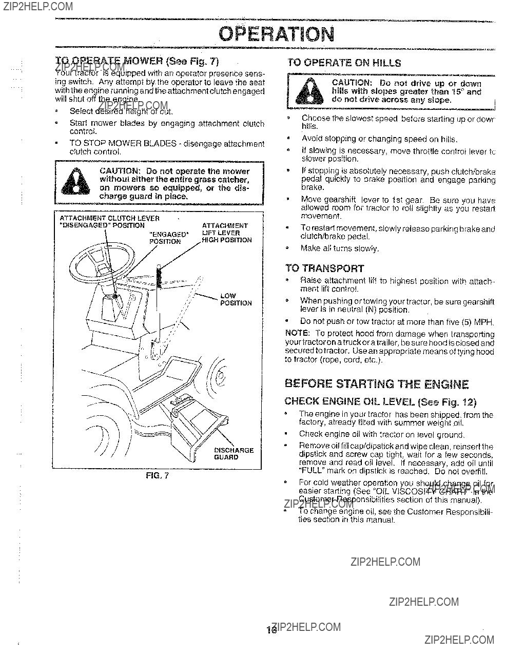
TO OPERATE MOWER (See Fig, 7)
Your tractor is equipped with an operator presence sens- ing switch. Any attempt by the operator to leave the seat with the engine running and the attachment clutch engaged will shut off the engine.
???Select desired height of cut.
???Start mower blades by engaging attachment clutch contro!.
??TO STOP MOWER BLADES - disengage attachment clutch control.
,_A without either the entire grass catcher,
J _ on mowers so equipped, or the dis- l
ATTACHMENT CLUTCH LEVER
"DISENGAGED" POSITIONATTACHMENT
"ENGAGED" LIFT LEVER POStTJON HIGH POSIT_ON
/?
/
POSITION
TO OPERATE ON HILLS
hilts with slopes greater than 15?? and CAUTION: Do not drive up or down do not drive across any slope.
Choose the slowest speed before starting up or dowr hiIIs.
???Avoid stopping or changing speed on hills.
If slowing is necessary, move throttle control lever tc slower position.
If stopping is absolutely necessary, push clutch/brake
pedal quickly to brake position and engage parking brake.
Move gearshift lever to 1st gear. Be sure you have
allowed room for tractor to roll slightly as you restart movement.
To restart movement, slowly release parking brake and clutch/brake pedal.
Make all turns slowly.
TO TRANSPORT
*Raise attachment lift to highest position with attach- ment lift control.
??When pushing or towing your tractor, be sure gearshift lever is in neutral (N) position.
,Do not push or tow tractor at more than five (5) MPH.
NOTE: To protect hood from damage when transporting your tractor on a truck or a trailer, be sure hood is closed and secured to tractor. Use an appropriate means of tying hood to tractor (rope, cord, etc.).
DISCHARGE
GUARD
BEFORE STARTmNG THE ENGINE
CHECK ENGINE OiL LEVEL (See Fig. 12)
??The engine in your tractor has been shipped, from the factory, already filled with summer weight oil.
-Check engine oil with tractor on level ground.
,Remove oil fill cap/dipstick and wipe clean, reinsert the dipstick and screw cap tight, wait for a few seconds, remove and read oil level. If necessary, add oil until "FULL" mark on dipstick is reached. Do not overfill.
oFor cold weather operation you should change oil for' easier starting (See "OtL VISCOSITY CHART" in the Customer Responsibilities section of this manual).
To change engine oil, see the Customer ResponsibiIF ties section in this manual.
13

OPERATBON
..... i
..... i
ADD GASOUNE
???Fill fuel tank, Use fresh, clean, regular unleaded gasoline. (Use of leaded gasoline will increase carbon and lead oxide deposits and reduce valve life).
IMPORTANT: WHEN OPERATING IN TEMPERATURES
BELOW 32??F(0??C), USE FRESH, CLEAN WINTER GRADE
GASOLINE TO HELP INSURE GOOD COLD WEATHER
STARTING.
WARNING: Experience indicates that alcohol blended fuefs (called gasohol or using ethanol or methanol) can attract moisture which leads to separation and formation of acids during storage. Acidic gas can damage the fuel system of an engine while in storage. To avoid engine problems, the fuel system should be emptied before stor- age of 30 days or longer. Drain the gas tank, start the engine and let it run until the fuel lines and carburetor are empty. Use fresh fuel next season. See Storage Instruc- tions for additional information. Never use engine or carburetor cleaner products in the fuel tank or permanent damage may occur.
TO START ENG|NE (See Fig. 6)
When starting engine for the first time or if engine has run out of fuel, it will take extra cranking time to move fuel from the tank to the engine.
???Depress clutch/brake pedal and set parking brake.
??Place gearshift lever in neutral (N) position.
,Move attachment clutch to "DISENGAGED" position.
oMove throttle control lever to choke (I\l) position for cold engine start. Forwarm engine start, move throttle control to fast (_) position.
???Insert key into ignition and turn key clockwise to"START" position and release key as soon as engine starts. Do not run starter continuously for more than fifteen seconds per minute, tf engine does not start after several attempts, move throttle control to fast (,f_) position, wait a few minutes and try again.
,When engine starts, move throttle control to desired position.
Allow engine to warm up for a few minutes before engaging drive or attachments.
NOTE: If at a high altitude (above 3000 feet) or in cold temperatures (below 32??F), the carburetor fuel mixture may need to be adjusted for best engine performance. See "TO ADJUST CARBURETOR" in the Service and Adjust- ments section of this manual.
MOWING TiPS
Tire chains cannot be used when the mower housing is attached to tractor,
??Mower should be properly leveled for best mowing performance. See "TO LEVEL MOWER HOUSING" in the Service and Adjustments section of this manual.
=The left hand side of mower should be used for trim- ming.
Drive so that clippings are discharged onto the area
that has been cut. Have the cut area to the right of the machine. This will result in a more even distribution of
clippings and more uniform cutting.
???When mowing large areas, start by turning to the right so that clippings will discharge away from shrubs, fences, driveways, etc. After one or two rounds, mow in the opposite direction making left hand turns until finished (See Fig. 8 ).
If grass is extremely tall, it should be mowed twice to reduce load and possible fire hazard from dried clip- pings. Make first cut relatively high; the second to the desired height.
???Do not mow grass when it is wet. Wet grass wili plug mower and leave undesirable clumps. Allow grass to dry before mowing.
???Always operate engine at full throttle when mowing to assure better mowing performance and proper dis- charge of material. Regulate ground speed by select- ing a low enough gear to give the mower cutting performance as well as the quality of cut desired.
=When operating attachments, select a ground speed that will suit the terrain and give best performance of the attachment being used.
FiG, 8
14
CUSTOM ESPONS LINES
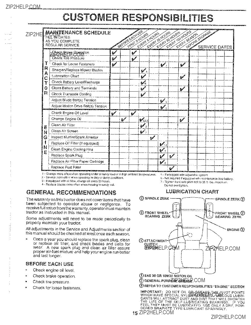
MAINTENANCE SCHEDULE
FILL IN DATES
AS YOU COMPLETE
REGULAR SERVICE
Check Brake Operation
Check Tire Pressure
Check for Loose Fasteners
R [ Sharpen/ReplaceMowerBtades
A
C LubricationChart
T Check Battery Level/Recharge
0 Clean Batteryand Termina{s
RCheck Transax/eCooIing Adjust Blade Belt(s)Tension
Adjust Motion Drive Belt(s) Tension
E
Check Engine Oil Level
Change Engine Oil
Clean Air Fitter
N [ Clean AirScreen
F
G Inspect Muffler/Spark Arrester
Replace Oil Filter(lf equipped)
N Clean EngineCoolingFins
E
Replace Spark Piug
Replace Air Filter Paper Cartridge
ReplaceFuel Fitter
GENERAL RECOMMENDATIONS
The warranty on this tractor does not cover items that have been subjected to operator abuse or negligence. To receive full value from the warranty, operator must maintain tractor as instructed in this manual.
Some adjustments will need to be made periodically to properly maintain your tractor,
All adjustments in the Service and Adjustments section of this manual should be checked at least once each season.
Once a year you should replace the spark plug, clean or replace air filter, and check blades and belts for wear. A new spark plug and clean air filter assure proper
ENGINE(_
G
CLUTCH
PWOT(S)
BEFORE EACH USE
oCheck engine oil level. Check brake operation.
,Check tire pressure.
o Check for loose fasteners.
(_) SAE 30 OR 10W30 MOTOR OIL
(_) GENERAL PURPOSE GREASE
(_ REFER TO CUSTOMER RESPONSIBILiTiES "ENGINE" SECTION
IMPORTANT: DO NOT OIL OR GREASE THE PIVOT POINTS
WHICH HAVE SPECIAL NYLON BEARINGS. VISCOUS LUBRI.- CANTS WILL ATTRACT DUST AND DIRT THAT WiLL SHORTEN
THE LIFE OF THE
FEEL THEY MUST BE LUBRICATED, USE ONLY A DRY, POW-
DERED GRAPHITE TYPE LUBRICANT SPARINGLY,
15
CUSTO RESPON IL ES
...... i
TRACTOR
Always observe safety rules when performing any mainte- nance.
BRAKE OPERATMON
If tractor requires more than six (6) feet stopping distance at high speed in highest gear, then brake must be adjusted. (See "TO ADJUST BRAKE" in the Service and Adjust- ments section of this manual).
TmRES
=Maintain proper air pressure in alt tires (See "PROD-
UCT SPECIFICATIONS" on page 3 of this manual).
???Keep tires free of gasoline, oil, or insect control chemi- cals which can harm rubber.
???Avoid stumps, stones, deep ruts, sharp objects and other hazards that may cause tire damage,
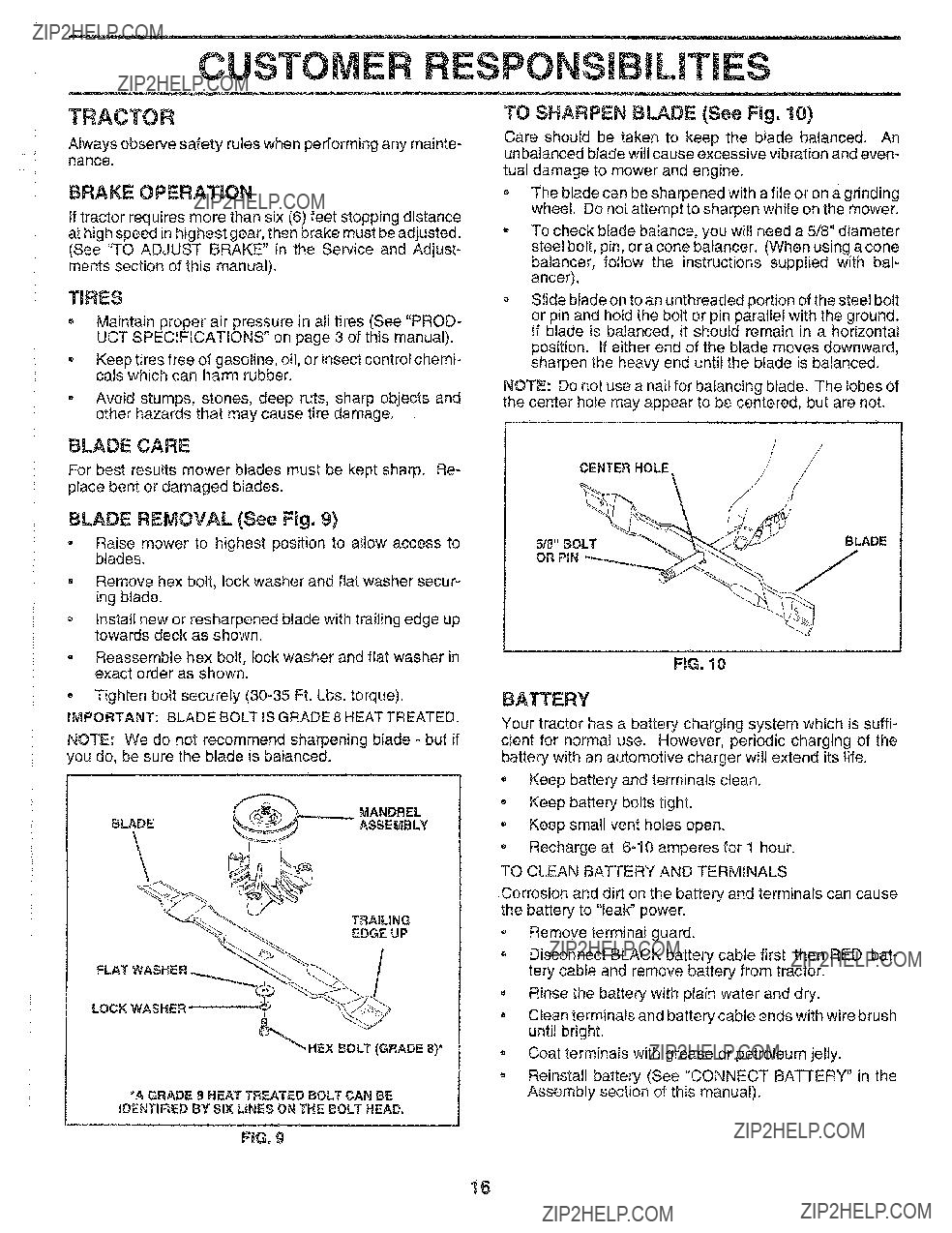
TO SHARPEN BLADE (See Fig. 10)
Care should be taken to keep the blade balanced. An unbalanced blade will cause excessive vibration and even-
tual damage to mower and engine.
oThe blade can be sharpened with a file or on a grinding wheel. Do not attempt to sharpen while on the mower.
To check blade balance, you will need a 5/8" diameter steel bolt, pin, or a cone bafancer. (When using a cone
baiancer, follow the instructions supplied with bai- ancer).
Slide blade on to an unthreaded portion of the steel bolt or pin and hold the bolt or pin parallel with the ground. If blade is balanced, it should remain in a horizontal position, if either end of the blade moves downward, sharpen the heavy end until the blade is balanced.
NOTE: Do not use a nail for balancing blade. The lobes of the center hole may appear to be centered, but are not,
BLADE CARE
For best results mower blades must be kept sharp. Re- place bent or damaged blades.
BLADE REMOVAL (See Fig. 9)
???Raise mower to highest position to allow access to blades.
oRemove hex bolt, lock washer and flat washer secur- ing blade.
oInstall new or resharpened blade with trailing edge up towards deck as shown.
Reassemble hex bolt, lock washer and flat washer in exact order as shown.
- Tighten bolt securely
IMPORTANT: BLADE BOLT IS GRADE 8 HEAT TREATED.
NOTE: We do not recommend sharpening blade - but if _oudo, be sure the blade is balanced.
FLAT
LOCK WASHER
*A GRADE 8 HEAT TREATED BOLT CAN BE
IDENTIFIED BY SIX LINES ON THE BOLT HEAD.
FIG. 9
CENTER HOLE
\
FiG. 10
BATTERY
Your tractor has a battery charging system which is suffi- cient for normal use. However, periodic charging of the battery with an automotive charger wilt extend its life.
??? Keep battery and terminals clean.
-Keep battery bolts tight.
??Keep small vent holes open.
Recharge at
TO CLEAN BATTERY AND TERMINALS
Corrosion and dirt on the battery and terminals can cause the battery to "leak" power.
o Remove terminal guard.
,Disconnect BLACK battery cable first then RED bat- tery cable and remove battery from tractor.
Rinse the battery with plain water and dry.
oClean terminals and battery cable ends with wire brush untit bright.
Coat terminals with grease or petroleum jelly.
=Reinstall battery (See "CONNECT BATTERY" in the Assembly section of this manual).
16
..... i
OUSTOME ESPONS L ES
Check
operation and replace if necessary. The belts are notCAPIDIPSTICK adjustable. Replace belts if they begin to slip from wear.
TRANSAXLE COOLING
Keep transaxle free from
ENG|NE
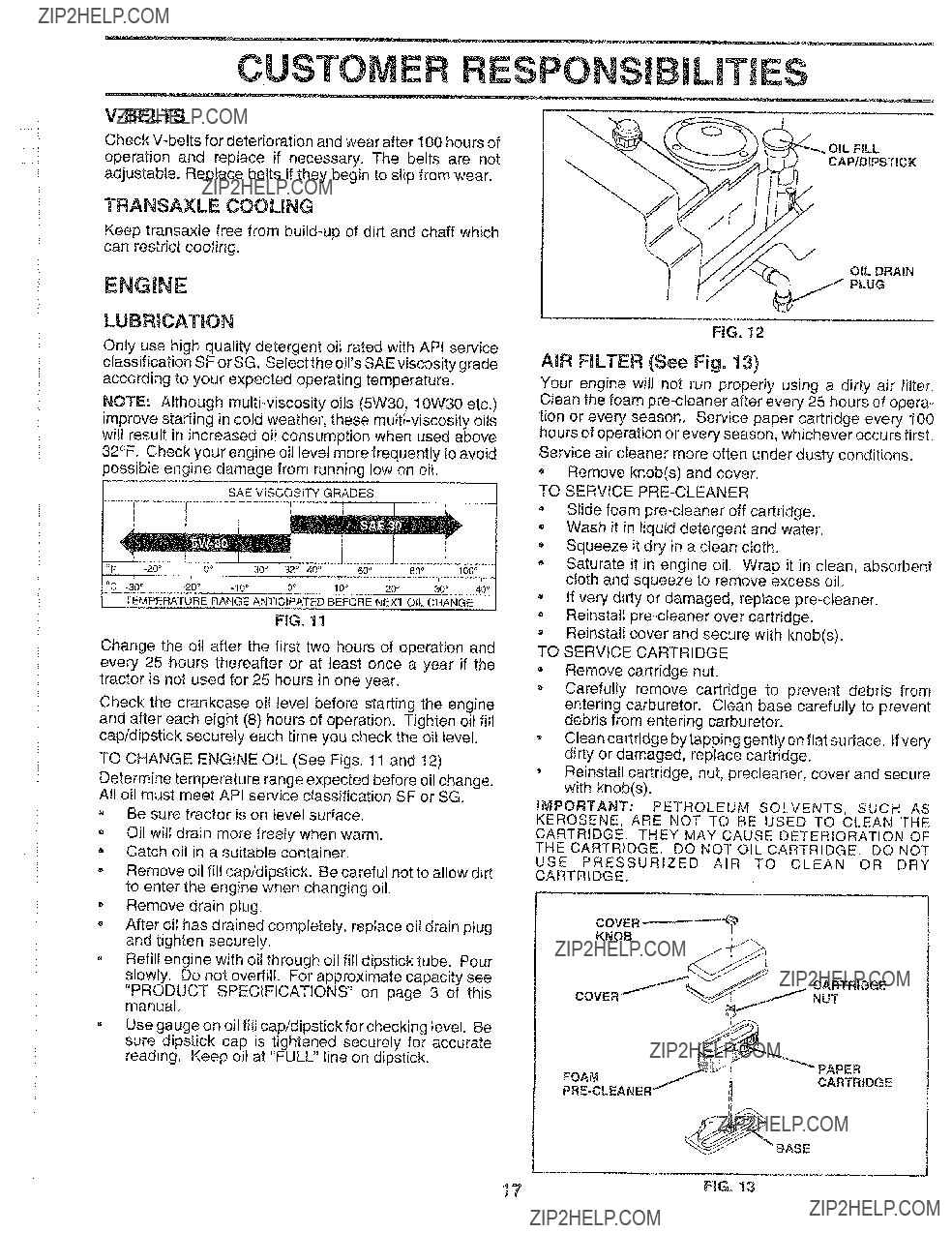
LUBRICATION
Only use high quality detergent oil rated with API service
classificatJon SF or SG. Selectthe oil'sSAE viscosity grade according to your expected operating temperature.
NOTE: Although
SAE ViSCOSiTY GRADES
TEMPERATURE RANGE ANTICIPATED BEFORE NEXT OIL CHANGE
FIG, 11
Change the oil after the first two hours of operation and every 25 hours thereafter or at least once a year if the tractor is not used for 25 hours in one year.
Check the crankcase oil level before starting the engine and after each eight (8) hours of operation. Tighten oil fill cap/dipstick secureiy each time you check the oil level.
TO CHANGE ENGINE OIL (See Figs. 11 and 12)
Determine temperature range expected before oil change. All oi! must meet APt service classification SF or SG.
???Be sure tractor is on ievel surface.
Oil will drain more freely when warm.
,Catch oil in a suitable container.
oRemove oil fill cap/dipstick. Be careful not to allow dirt to enter the engine when changing oil.
o Remove drain plug.
,After oi! has drained completely, replace oil drain plug and tighten securely.
oRefill engine with oil through oil fill dipstick tube. Pour slowly. Do not overfill. For approximate capacity see
"PRODUCT SPECIFICATIONS" on page 3 of this manual.
???Use gauge on oil fill cap/dipstick for checking level. Be sure dipstick cap is tightened securely for accurate reading. Keep oil at "FULL" line on dipstick.
OIL DRAIN
PLUG
FIG. 12
AIR FILTER (See Fig. 13)
Your engine wilt not run properly using a dirty air filter. Clean the foam
tion or every season. Service paper cartridge every I00 hours of operation or every season, whichever occurs first.
Service air cleaner more often under dusty conditions. Remove knob(s) and cover.
TO SERVICE
Slide foam
-Wash it in liquid detergent and water. Squeeze it dr;/in a clean cloth.
Saturate it in engine oil. Wrap it in clean, absorbent cloth and squeeze to remove excess oil.
If very dirty or damaged, replace
,Reinstall pre.cleaner over cartridge.
o Reinstall cover and secure with knob(s).
TO SERVICE CARTRIDGE
???Remove cartridge nut.
???Carefully remove cartridge to prevent debris from entering carburetor. Clean base carefu!ly to prevent debris from entering carburetor.
Clean cartridge by tapping gently on flat su #dace. tfvery dirty or damaged, replace cartridge.
Reinstall cartridge, nut, precleaner, cover and secure with knob(s).
IMPORTANT: PETROLEUM SOLVENTS, SUCH AS
KEROSENE, ARE NOT TO BE USED TO CLEAN THE
CARTRIDGE. THEY MAY CAUSE DETERIORATION OF
THE CARTRIDGE. DO NOT OIL CARTRIDGE. DO NOT
USE PRESSURIZED AIR TO CLEAN OR DRY
CARTRIDGE.
COVER
KNOB

CUSTOMEILITI
CLEAN AIR SCREEN (See Fig. 14)
ENGINE COOLING FINS (See Fig. 14)
Remove any dust, dirt or oil from engine cooling fins to prevent engine damage from overheating.
* Remove screws from blower housing and lift housing and oil fiti tube assembly off engine,
, Cover oil fill opening to prevent entry of dirt.
, Remove the screws securing the starter housing and lift housing off engine.
, Use compressed air or stiff bristle brush to thoroughly clean engine cooling fins.
o To reassemble, reverse above procedure.
SCREWS
BLOWER HOUSING
SCREWS
AIR SCREEN
OIL FiLL
TUBE
ASSEMBLY
FiG. 14
MUFFLER
Inspect and replace corroded muffler and spark arrester (if equipped) as it could create afire hazard and/or damage.
SPARK PLUGS
Replace spark plugs at the beginning of each mowing season or after every 100 hours of operation, whichever occurs first. Spark plug type and gap setting are shown in "PRODUCT SPEC IFICATtONS" on page 3 of this manual.
The fuel filter should be replaced once each season. If fuel filter becomes clogged, obstructing fuel flow to carburetor, replacement is required.
??With engine cool, remove filter and plug fuel line sections.
???Place new fuel filter in position in fuel line with arrow pointing towards carburetor.
??Be sure there are no fuel line leaks and clamps are properly positioned.
,immediately wipe up any spilled gasoline.
FIG. 15
CLEANING
???Clean engine, battery, seat, finish, etc. of all foreign matter.
???Keep finished su rfaces and wheels free of all gasoline, oil, etc.
??Protect painted surfaces with automotive type wax,
We do not recommend using a garden hose to clean your tractor unless the electrical system, muffler, air filter and carburetor are covered to keep water out. Water in engine can result in a shortened engine life.
18

??? ,,,,z
........ i
...... ! i
i
i
ERVICE A ADJ STMENTS
CAUTION: BEFORE PERFORMING ANY SERVICE OR ADJUSTMENTS:
?? Depress clutch/brake pedal fully and set parking brake,
,Place gearshift lever in neutrat (N) position.
Ptace attachment clutch in "DISENGAGED" position.
-Turn ignition key "OFF" and remove key.
Make sure the blades and all moving parts have completely stopped.
,Disconnect spark plug wire from spark plug and ptace wire where it cannot come in contact with plug.
TO REMOVE MOWER (See Fig. 16)
Mower will be easier to remove from the rightside of tractor.
,Place attachment clutch in "DISENGAGED" position,
=Move attachment lift lever forward to lower mower to its lowest position.
???Roll belt off engine putley.
-Disconnect clutch rod from clutch lever by removing retainer spring.
oDisconnect
,Disconnect suspension arms from rear deck brackets by removing retainer springs.
oDisconnect front links from deck by removing retainer springs.
Raise lift lever to raise suspension arms. Slide mower out from under tractor.
IMPORTANT: JFAN ATTACHMENT OTHER THAN THE
MOWER IS TO BE MOUNTED TO THE TRACTOR, THE
R.H, AND L.H, SUSPENSION ARMS MUST BE REMOVED
FROM TRACTOR,
TO iNSTALL MOWER (See Fig. 16)
*Raise attachment lift lever to its highest position.
,Slide mower under tractor with discharge guard to right side of tractor.
*Lower lift lever to its lowest position.
o Instal mower in reverse order of removal instructions.
RETAINER
SPRING
/
RETAINER
SPRINGS
(BOTH SIDES)
FiG. 16
19

SERVICE AN ADJUSTMENTS
.... i
E
Ji
TO LEVEL MOWER HOUSING
Adjust the mower while tractor is parked on level ground or driveway. Make sure tires are properly inflated (See "PRODUCT SPECIFICATIONS" on page 3of this manual). Iftires are over or underinflated, you will not properly adjust your mower.
Raise mower to its highest position.
???At the midpoint of both sides of mower, measure height
from bottom edge of mower to ground. Distance "A" on both sides of mower should be the same or within 1/4" of each other.
If adjustment is necessary, make adjustment on one side of mower only.
To raise one side of mower, tighten lift link adjustment nut on that side.
To lower one side of mower, loosen lift link adjustment nut on that side.
NOTE: Each full turn of adjustment nut will change mower height about t/8".
-Recheck measurements after adjusting.
GROUND LINE
RG. !7
SUSPENSION
ARM
UFT UNK
ADJUSTMENT NUT
FtG. 18
iMPORTANT: DECK MUST BE LEVEL
THE FOLLOWING
NECESSARY, BE SURE TO ADJUST BOTH FRONT LINKS
EQUALLY SO MOWER WILL STAY LEVEL
To obtain the best cutting results, the mower housing should be adjusted so that the front is approximately 1/4" to 3/4" lower than the rear when the mower is in its highest position.
Check adjustment on right side of tractor. Measure dis- tance "D" directly in front and behind the mandrel at bottom edge of mower housing as shown.
Before making any necessary adjustments, check that both front links are equal in length. Both links should be approximately
???If links are not equal in length, adjust one link to same length as other link.
To lower front of mower loosen nut "E" on both front links an equal number of turns.
When distance "D" is t/4" to 3/4" lower at front than
rear, tighten nuts "F" against trunnion on both front links.
To raise front of mower, loosen nut"F" from trunnion on both front links. Tighten nut "E" on both front links an equal number of turns.
When distance "D" is 1/4" to 3/4" lower at front than rear, tighten nut "F" against trunnion on both front links.
Recheck
FiG. 19
BOTH FRONT LItNKSMUST BE EQUAL IN LENGTH
NUT "E"
NUT "F"
ERVICE ADJUSTMENTS
TO REPLACE MOWER BLADE DRIVE BELT
(See Fig. 21)
....... i
The mower blade drive bett may be replaced without tools. Park the tractor on feve! surface. Engage parking brake.
BELT REMOVAL-
-Remove mower from tractor (See "TO REMOVE MOWER" in this section of this manual).
,Work belt off both mandrel pulleys and idler pulleys.
,Pull belt away from mower.
BELT INSTALLATION -
,Install new belt in reverse order of removal.
oMake sure belt is in all pulley grooves and inside all belt guides.
-Install mower in reverse order of removal instructions.
MANDREL IDLER
PULLEYPULLEYS
MANDREL
PULLEY
FiG, 2t
TO ADJUST BRAKE (See Fig. 22)
Your tractor is equipped with an adjustable brake system which is mounted on the right side of the transaxle.
If tractor requires more than six (6) feet stopping distance at high speed in highest gear, then brake must be adjusted.
*Dep tess clutch/brake pedal and engage parking b rake.
Measure distance between brake operating arm and nut "A" on brake rod,
If d!stance is other than 1
Road test tractor for proper stopping distance as stated above. Readjust if necessary. If stopping distance is still greater than six (6) feet in highest gear, further maintenance is necessary. Contact your nearest au- thorized service centeddepartment.
WITH PARKING BRAKE "ENGAGED"
\
\
\ \
NUT
OPERATING
ARMi
!
FiG. 22
TO REPLACE MOTION DRIVE BELT
(See Fig, 23)
Park the tractor on level surface. Engage parking brake. For assistance, there is a belt installation guide decal on bottom side of left footrest.
???Remove mower (See "TO REMOVE MOWER" in this section of this manual.)
???Remove upper belt keeper.
=Remove belt from stationary idler and clutching idler. Pull belt slack toward rear of tractor. Remove belt
upwards from transaxle pulley by deflecting belt keep- ers.
-Pull belt toward front of tractor and remove downwards from around engine pulley.
o Install new belt by reversing above procedure.
IMPORTANT: MAKE SURE UPPER BELT KEEPER IS
POSITIONED PROPERLY BETWEEN LOCATOR TABS.
PULLEY
IDLER
KEEPER
iDLER
TRANSA>
PULLEY

.... :!
SERVICE AN
TO ADJUST STEERING WHEEL ALIGNMENT
If steering wheel crossbars are not honzontal (left to right)
when wheels are positioned straightforward, remove steer- ing wheel and reassemble per instructions in the Assembly section of this manual.
FRONT WHEEL
The front wheel
TO REMOVE WHEEL FOR REPAIRS
(See Fig. 24)
???Block up axle securely,
,Remove axle cover, retaining dng and washers to allow wheel removal (rear wheel contains a square key - Do not lose).
,Repair tire and reassemble,
-On rear wheels only: align grooves in rear wheel hub and axle. Insert square key.
???Replace washers and snap retaining ring securely in axle groove.
???Replace axle cover.
ADJUSTMENTS
TO START ENGINE WiTH A WEAK BATTERY
{See Fig. 25)
CAUTION:
ate e??plosive gases, Keepsparks, flame and smoking materials away from bat-
teries. Always wear eye protection when around batteries,
If your battery is too weak to start the engine, it should be recharged. If "jumper cables" are used for emergency starting, follow this procedure:
iMPORTANT: YOUR TRACTOR iS EQUIPPED WiTH A 12
VOLT NEGATIVE GROUNDED SYSTEM. THE OTHER
VEHICLE MUST ALSO BE A 12 VOLT NEGATIVE
GROUNDED SYSTEM. DO NOT USE YOUR TRACTOR
BATTERY TO START OTHER VEHICLES.
TO ATTACH JUMPER CABLES -
*Connect each end of the RED cable to the POSITIVE
(+)terminal of each batter:/, taking care not to short against chassis.
Connect one end of the BLACK cable to the NEGA- TIVE
Connect the other end of the BLACK cable to good CHASSIS GROUND, away from fuel tank and battery.
TO REMOVE CABLES, REVERSE ORDER -
,BLACK cable first from chassis and then from the fully charged battery.
=RED cable last from both batteries.
BATTERY
FIG. 25
22
SERVICE AND ADJUSTMENTS
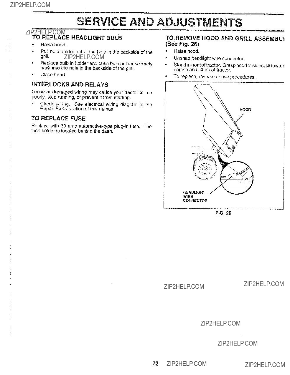
TO REPLACE HEADLIGHT BULB
*Raise hood.
,Pull bulb holder out of the hole in the backside of the grill.
=Replace bulb in holder and push bulb holder securely back into the hole in the backside of the grill.
,Close hood.
TO REMOVE HOOD AND GRILL ASSEMBL_
(See Fig, 26)
,Raise hood.
Unsnap headlight wire connector.
Stand in front of tractor. Grasp hood at sides, tilt towarc engine and lift off of tractor.
=To replace, reverse above procedures.
INTERLOCKS AND RELAYS
Loose or damaged wiring may cause your tractor to run poorly, stop running, or prevent it from starting.
TO REPLACE FUSE
Replace with 30 amp automotive4ype
HEADLIGHT
WIRE
CONNECTOR
FIG, 26
23
SERVICE A
ENGINE
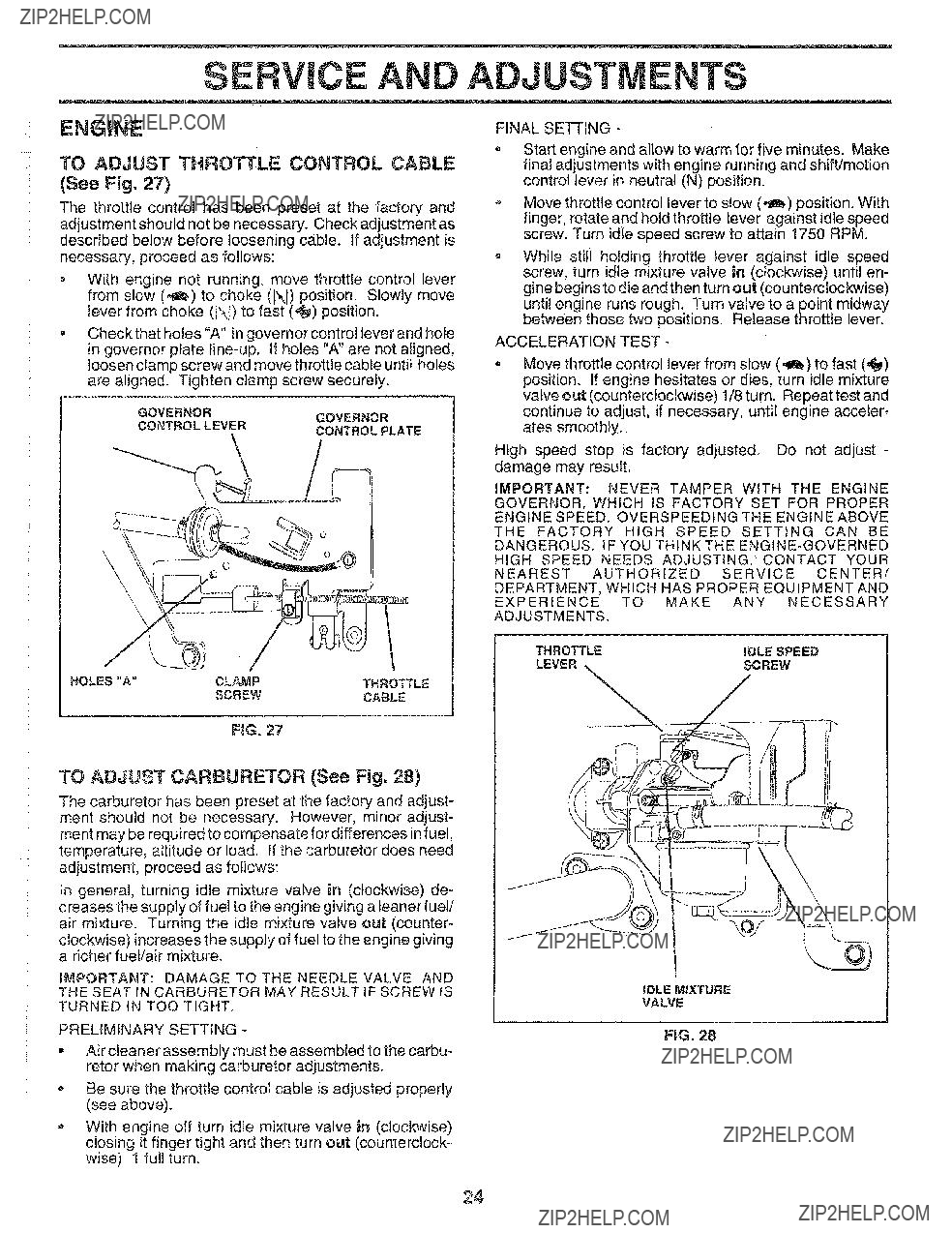
TO ADJUST THROTTLE CONTROL CABLE
(See Fig. 27)
The throttle control has been preset at the factory and adjustment should not be necessary. Check adjustment as described below before loosening cable. If adjustment is necessary, proceed as follows:
???With engine not running, move throttle control lever from slow (,_) to choke (XI) position. Slowly move lever from choke (N) to fast (_) post on.
???Check that holes "A" in governor control lever and hole in governor plate
/
A JUSTMENTS
FINAL SETTING *
,Start engine and allow to warm for five minutes. Make fina! adjustments with engine running and shift/motion control lever in neutral (N) position.
*Move throttle control lever to slow (,_!) position, With finger, rotate and hold throttle lever against idle speed screw, Turn idle speed screw to attain 1750 RPM,
,While still holding throttle lever against idle speed screw, turn idle mixture valve in (clockwise) until en- gine begins to die and then turn out (counterclockwise) until engine runs rough. Turn valve to a point midway between those two positions. Release throttle lever.
ACCELERATION TEST -
???Move throttle control lever from slow (,_!,) to fast (,_) position. If engine hesitates or dies, turn idle mixture valve out (counterclockwise) 1/8 turn. Repeat test and continue to adjust, if necessary, until engine acceler- ates smoothly.
High speed stop is factory adjusted. Do not adjust - damage may result.
IMPORTANT: NEVER TAMPER WiTH THE ENGINE
GOVERNOR, WHICH iS FACTORY SET FOR PROPER
ENGINE SPEED. OVERSPEEDING THE ENGINE ABOVE
THE FACTORY HIGH SPEED SETTING CAN BE DANGEROUS. IF YOU THtNKTHE
HIGH SPEED NEEDS ADJUSTING, CONTACT YOUR
NEAREST AUTHORIZED SERVICE CENTER/
DEPARTMENT, WHICH HAS PROPER EQUIPMENT AND
EXPERIENCE TO MAKE ANY NECESSARY
ADJUSTMENTS.
TO ADJUST CARBURETOR (See Fig. 28)
The carburetor has been preset at the factory and adjust- ment should not be necessary. However, minor adjust- ment may be required to compensate for differences infuel, temperature, altitude or load. if the carburetor does need adjustment, proceed as follows:
In general, turning idle mixture valve in (clockwise) de- creases the supply of fuel to the engine giving a leaner fuel/ air mixture. Turning the idte mixture valve out (counter-
clockwise) increases the supply of fuel to the engine giving a richer fuel/air mixture.
#_PORTANT: DAMAGE TO THE NEEDLE VALVE AND
THE SEAT IN CARBURETOR MAY RESULT IF SCREWIS
TURNED IN TOO TIGHT.
PRELIMINARY SETTING -
???Air cleaner assembly must be assembled to the carbu- retor when making carburetor adjustments.
oBe sure the throttle control cable is adjusted properly (see above).
oWith engine off turn idle mixture valve in (clockwise) dosing it finger tight and then turn out (counterclock?? wise) 1 full turn.
iDLE M_XTURE
VALVE
FIG. 28
24

STORAGE
-Fully charge the battery for storage.
Cover your tractor with a suitable protective cover that does not retain moisture. Do not use plastic. Plastic cannot breathe which allows condensation to form and wilt cause your tractor to rust.
]ivIPORTANT: NEVER COVER TRACTOR WHILE ENGINE
AND EXHAUST AREAS ARE STILL WARM.
25

Wil| not start
Hard to start
Engine will not turn over
Engine clicks but wilt not start
Loss of power
1.Replace blade. Tighten blade bolt,
2.Replace blade mandrel.
3.Tighten loose part(s). Replace damaged parts.
26

TROU LESHOOTING POINTS
PROBLEM
27

SERVICE NOTE
28

TRACTOR - = MODEL NUMBER 917.256500
SCHEMATIC
BATTERY
STARTER
BLACK
BLACK
II
AFTER FIRE SOLENOID
29
REPAmRPARTS
TRACTOR
ELECTRICAL
z
22
21
36
\
/
\
/
\
/
6
30
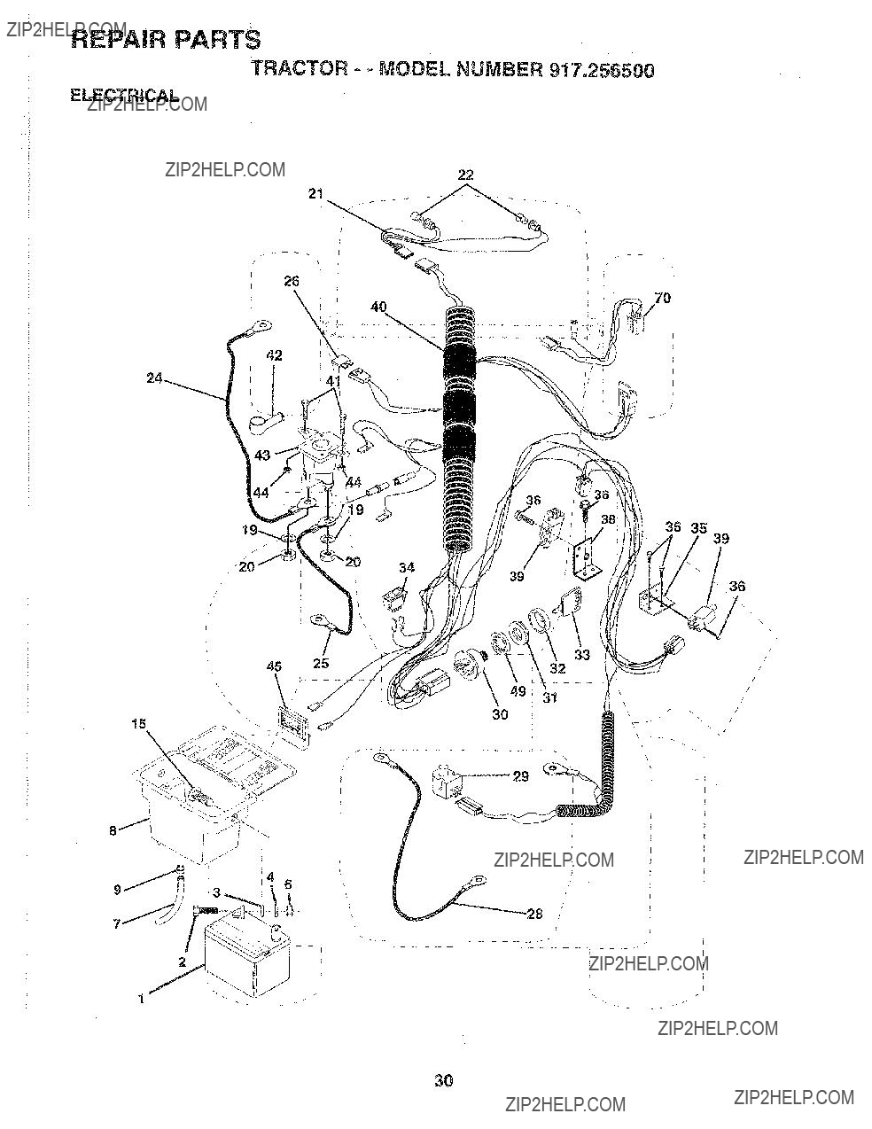
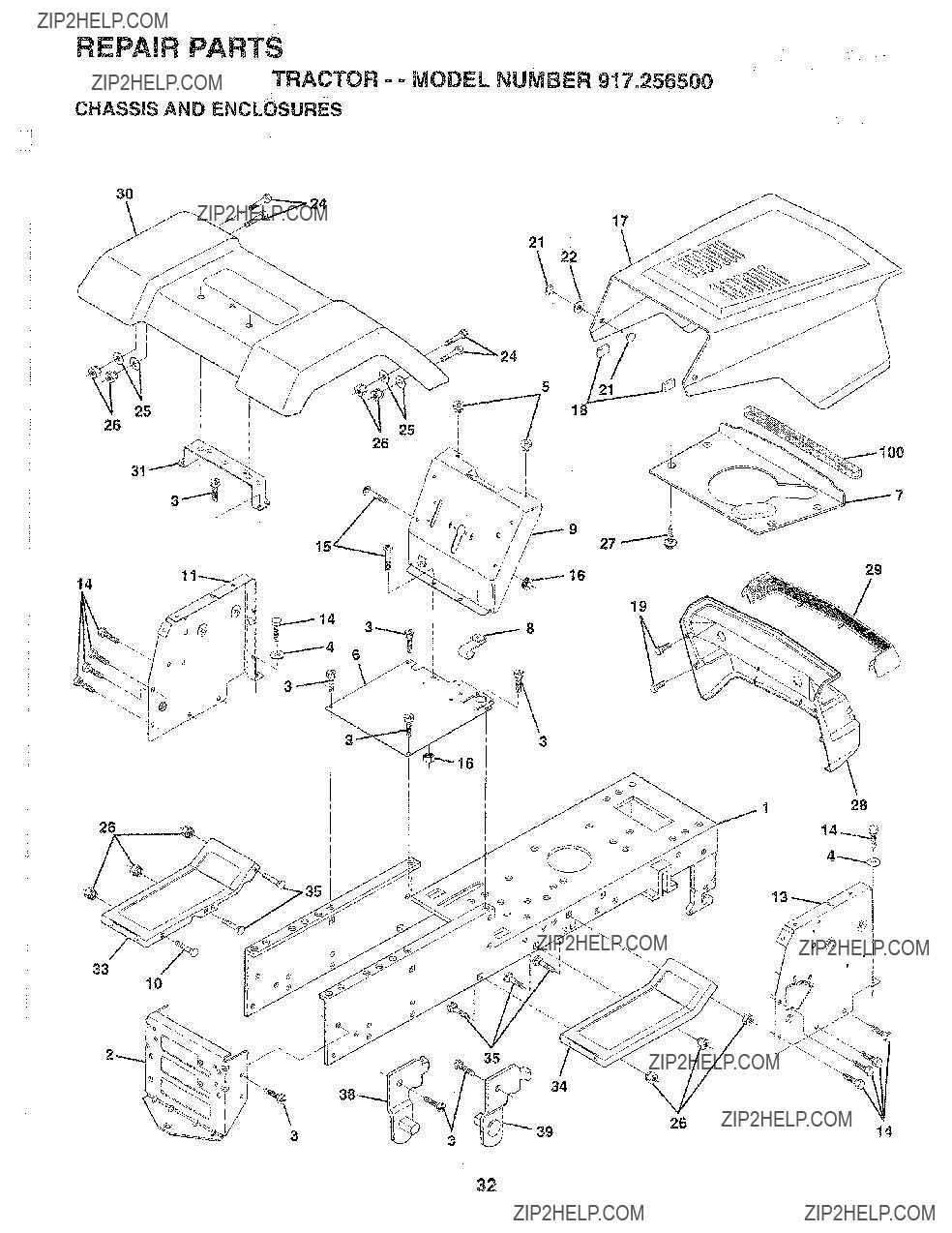
REPAIR PARTS
TRACTOR - - MODEL NUMBER 917.256500
ELECTRICAL
....... i
KEY PART
NO. NO= DESCRiPTiON
2STD523107 Bolt Hex Hd
3STD551025 Washer 9/32 X 5/8 X 16 Ga
4STD551125 Washer Lock Hvy Helical 1/4
6STD54t025 Nut Fin Hex
4171110408 Bolt Bfk Hex
42131563 Cover Terminal Red
_z
NOTE: Att component dimensions given in U.S. inches ! inch = 25.4 mm
31
REPAIR PARTS
TRACTOR
CHASSIS AND ENCLOSURES
.... i
3O
17
21\ \
5
18
26
31
9
29
3
33
!0
3
32
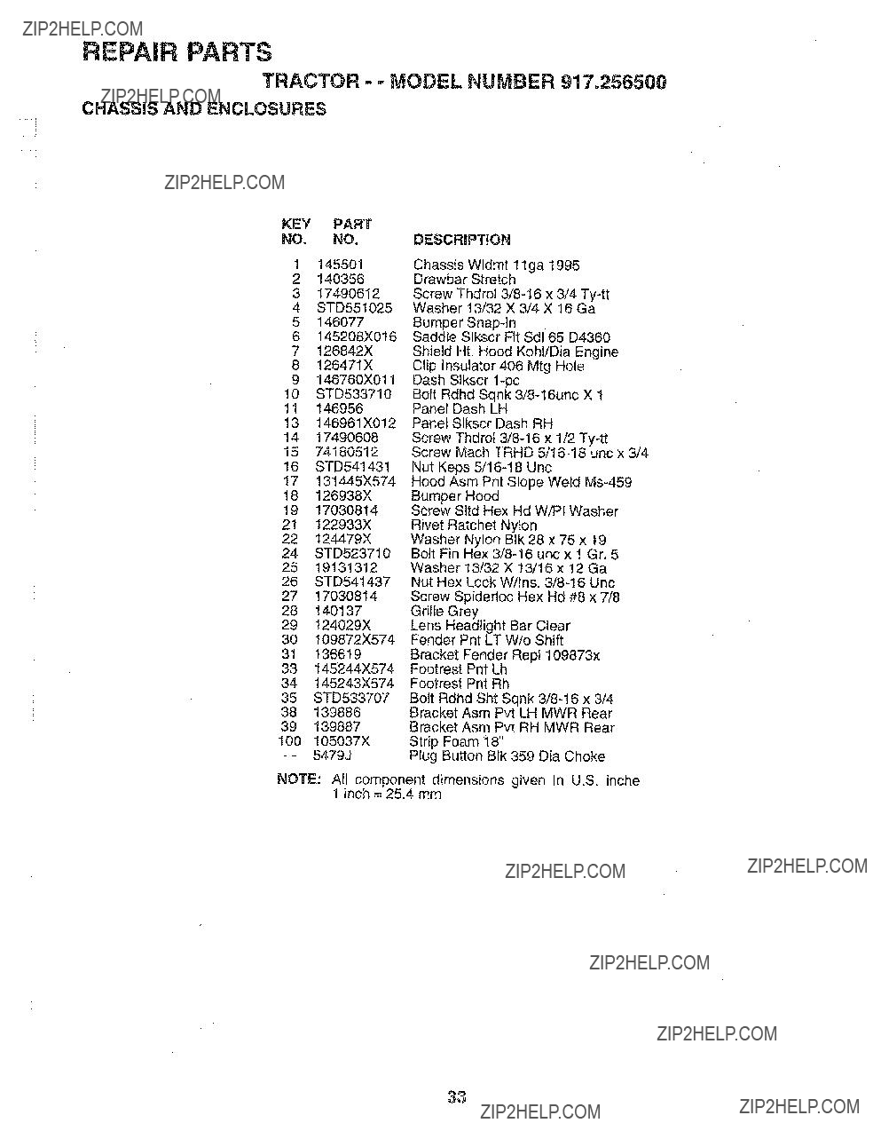
REPAIR PARTS
TRACTOR - = MODEL NUMBER 917.256500
CHASSIS AND ENCLOSURES
9146760X011 Dash Slkscr
10STD533710 Bolt Rdhd Sqnk
16STD541431 Nut Keps
17131445X574 Hood Asm Pnt Slope Weld
18126938X Bumper Hood
1917030814 Screw SItd Hex Hd W!PI Washer
24STD523710 Bolt Fin Hex
2519131312 Washer 13/32 X 13/16 x 12 Ga 26 STD541437 Nut Hex Lock W/Ins.
33145244X574 Footrest Pnt Lh
34145243X574 Footrest Pnt Rh
35STD533707 Bolt Rdhd Sht Sqnk
NOTE: All component dimensions given in U.S, inche 1 inch = 25.4 mm
33
/
/
"" MODELNUMBER9"!7,256,_00
57
/
/
/
/
i
63 _ \
/
\
\
\
1
/:
6
\
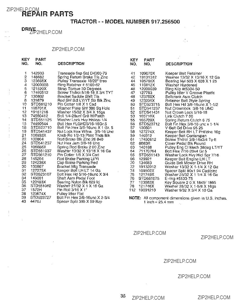
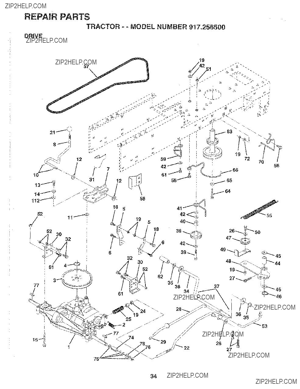
REPAIR PARTS
TRACTOR o.. MODEL NUMBER 917o256500
DRIVE
35
REPAIRPARTS
TRACTOR - - MODEL NUMBER 917.256500
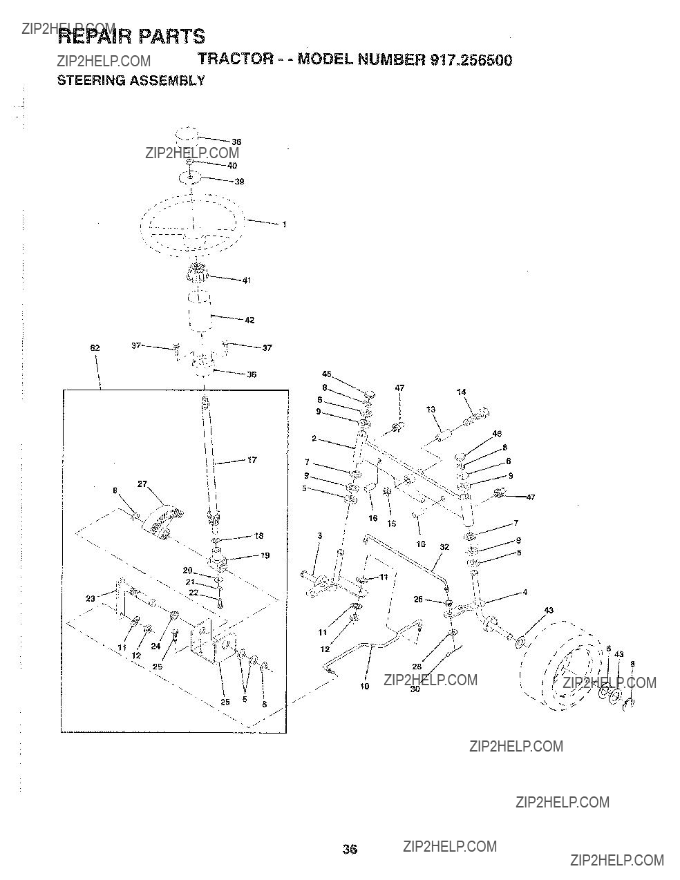
STEERING ASSEMBLY
...... i
.... i
_L
F
62
46
i
8_47
12
J
36

REPAIR PARTS
TRACTOR - - MODEL NUMBER 917o256500
STEERING ASSEMBLY
KEY PART
NO. NO.
1139768
2142033
3135227
4135228
56266H
6121748X
719272016
812000029
93366R
10 130468
1t STD551!37
12 73610600
t3 !!0438X
14 74011056
15 73901000
16132624
17132614
1857079
19124035X
20126684X
21STD551125
2271070410
23 127501
24 109816X
25 t24036X
26 126847X
27 136874
2819131416
2917490612
30STD561210
32130465
36132196
3717431008
38139769
3919133808
40STD541537
41104820X
42124417X
43121749X
46121232X
47 6855M
62 149684
DESCRBPT_ON
Wheel Steering Opp Sears Blk Axle Asm Front Lt
Spindle Asm Lh
Spindle Asm Rh
Washer Thrust .75 x 1.230 Washer 25/32 x
Bearing Cot Strg Blk
Link Drag Sol Ball Jt 20.064 Washer Lock Hvy Htcl Spr 3/8 Nut Fin Hex
Spacer Bearing Axle Front Bolt, Hex
Locknut Flange
Pin Axle 5/8 x 1.55/I .54 Lg Shaft Asm Strg 5/8 x 15.19 Lt Washer Thrust .515 x .750 x .033
Support Shaft
Washer Shim 1/4 x 5/8 x .062
Washer Lock Hvy Helical 1/4 Screw Hex Socket
Nyliner Snap tn Bracket Steering
Bushing Link Drag Blk LR Gear Sector 22 Teeth
Washer 13/32 x 7/8 x !6 Ga. Screw Thdrot
Rod Tie Wire Form 19.75 Mech Bushing Strg. 5/8 ID Dash Screw Slftp
Adaptor Wheel Strg..640/.635 Id
Boot Shaft Steering Craftsman Washer 25/32 x
Cap Spindle Fr Top Btk
Fitting Grease
Steering Assembly
NOTE: All component dimensions given in U.S. inches ", 1 inch = 25.4 mm
37

REPAIR PARTS
TRACTOR =- MODEL NUMBER 917,256500
ENGINE
...... !
.... i
3
72
62
8113
4
r
44
31
33
37
4033
23
OPTIONAL EQUIPMENT
Spark Attester
38

REPAIR PARTS
TRACTOR - - MODEL NUMBER 917.256500
ENGINE
32123549X Cap Asm Fuel W/sym Vented
33123487X Clamp Hose Blk
NOTE: All component dimensions given in U.S. inches 1 inch = 25.4 mm
39
REPAIR PARTS
TRACTOR = - MODEL NUMBER 917.256500
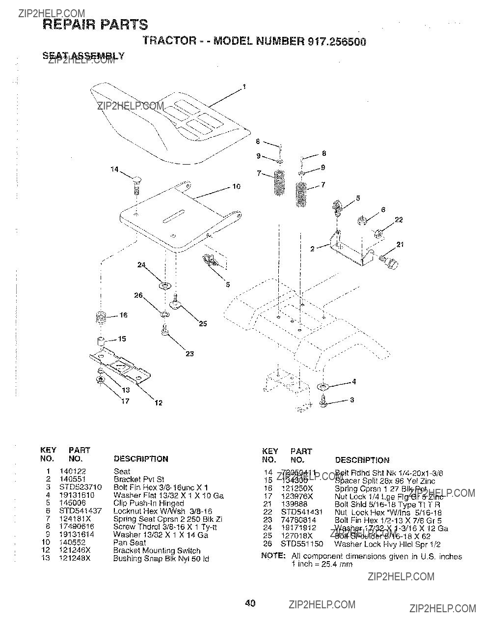
SEAT ASSEMBLY
......!
\
\ \
14
5
12
2374780814 Bolt Fin Hex
2419171912 Washer t7/32 X
25127018X Bolt Shoulder
26STD551150 Washer Lock Hvy Hlcl Spr 1/2
NOTE: All component dimensions given in U.S. inches 1 inch = 25.4 mm
4O
REPAIR PARTS
TRACTOR- = MODEL NUIVlBER 917.258500
DECALS
\
16
13
KEY PART
NO. NO,
t 138955
2272937
3150676
4150677
5150680
6133644
7142235
8140837
9!25880X
10149516
11137537
15
18
WHEELS & TIRES
KEY PART
NO, NO.
DESCRIPTION
Cap Valve Tire Stem Valve
Tire F Ts 15 X 6 0 - 6 Service
Tube Front (Service Item Only) Rim Asm 6" front White Service
Fitting Grease (Front Wheel Only) Bearing Flange (Front Wheel Only) Rim Asm 8" rear White Service Tire R Ts t8x8
Tube Rear (Service Item Only) Cap Hub Axle Blk ! 50 X ! 00 Sealant, Tire (10 oz. Tube)
NOTE: All component dimensions given in U,S. inches 1 inch = 25,4 mm
41

REPAIR PARTS
TRACTOR - - MODEL NUMBER 917.256500
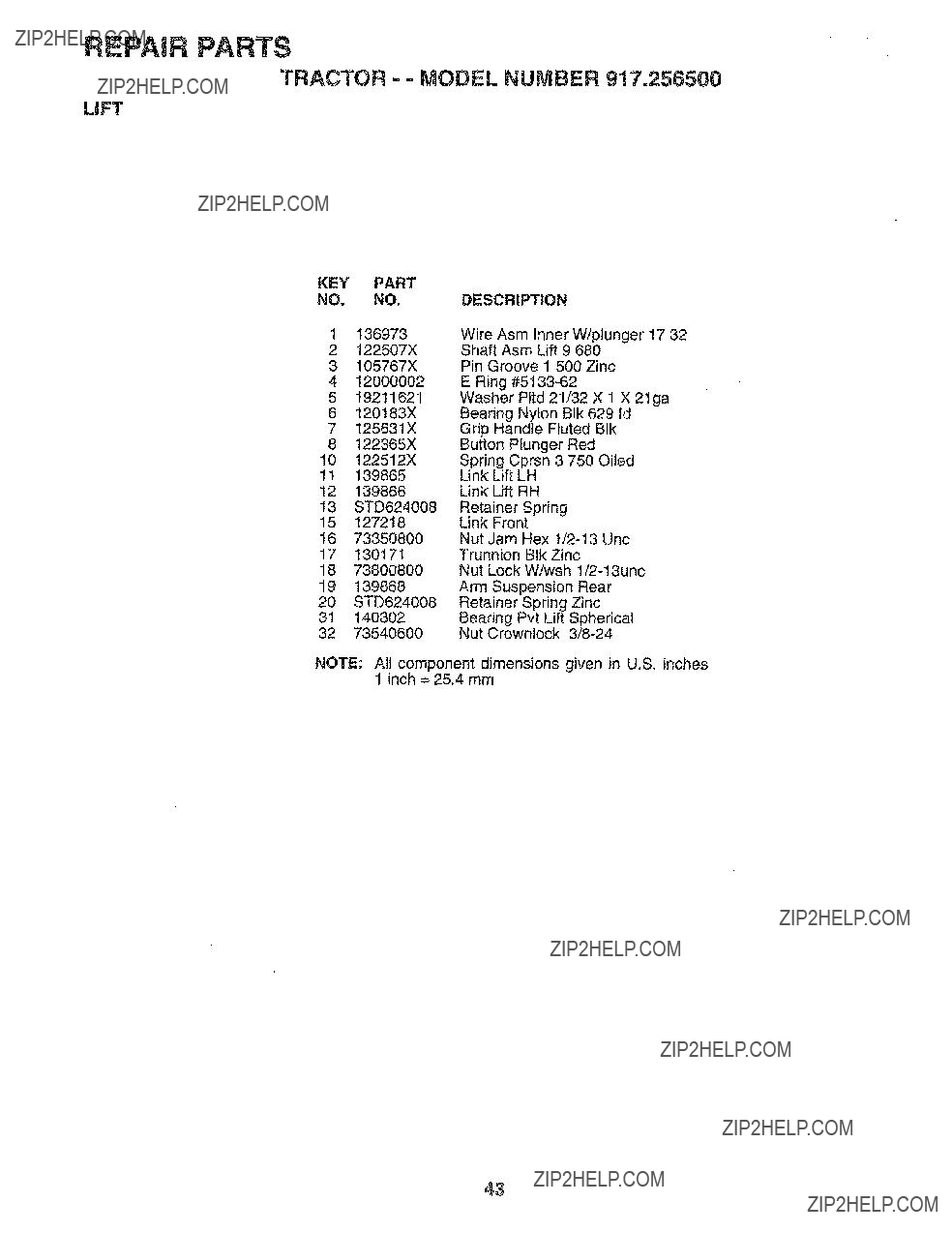
LiFT
...... !
..... !
]
7
5
4
6
12
13
19
l.j__ =o \\_>_J
3219
.J_> :zu \
42
REPAIR PARTS
TRACTOR - - MODEL NUMBER 9!7.256500
LiFT
KEY PART
NO, NO.DESCRIPTION
2122507X Shaft Asm Lift 9 680
3105767X Pin Groove 1 500 Zinc
NOTE: All component dimensions given in U.S. inches 1 inch = 25.4 mm
43

REPAIR PARTS
TRACTOR
MOWER
I
\
2
27
29
18
44
REPAIR PARTS
TRACTOR == MODEL NUMBER 917.256500
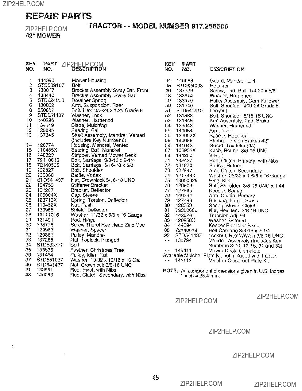
42" MOWER
KEY PART
NO. NO.
1 144393
2STD533107
3138017
4138440
5STD624008
6130832
8850857
9STD551137
10140296
11134149
12129895
i3 137645
14128774
15110485X
16140329
177211O61O
1872140505
19132827
20 136888
21 STD54t437
22 134753
23 131267
24 t05304X
25 123713X
26 110452X
27 130968
28 19111016
29 131491
30 138776 3! 129963
32129861
33137266
34STD533717 35 133835 36 131494
37 STD551037
40 STD541437
41 !33551
43 140083
45

REPAIR PARTS
TRACTOR o- MODEL NUMBER 917.256500
DANA TRANSAXLE - MODEL NUMBER
21
1
37
42
46
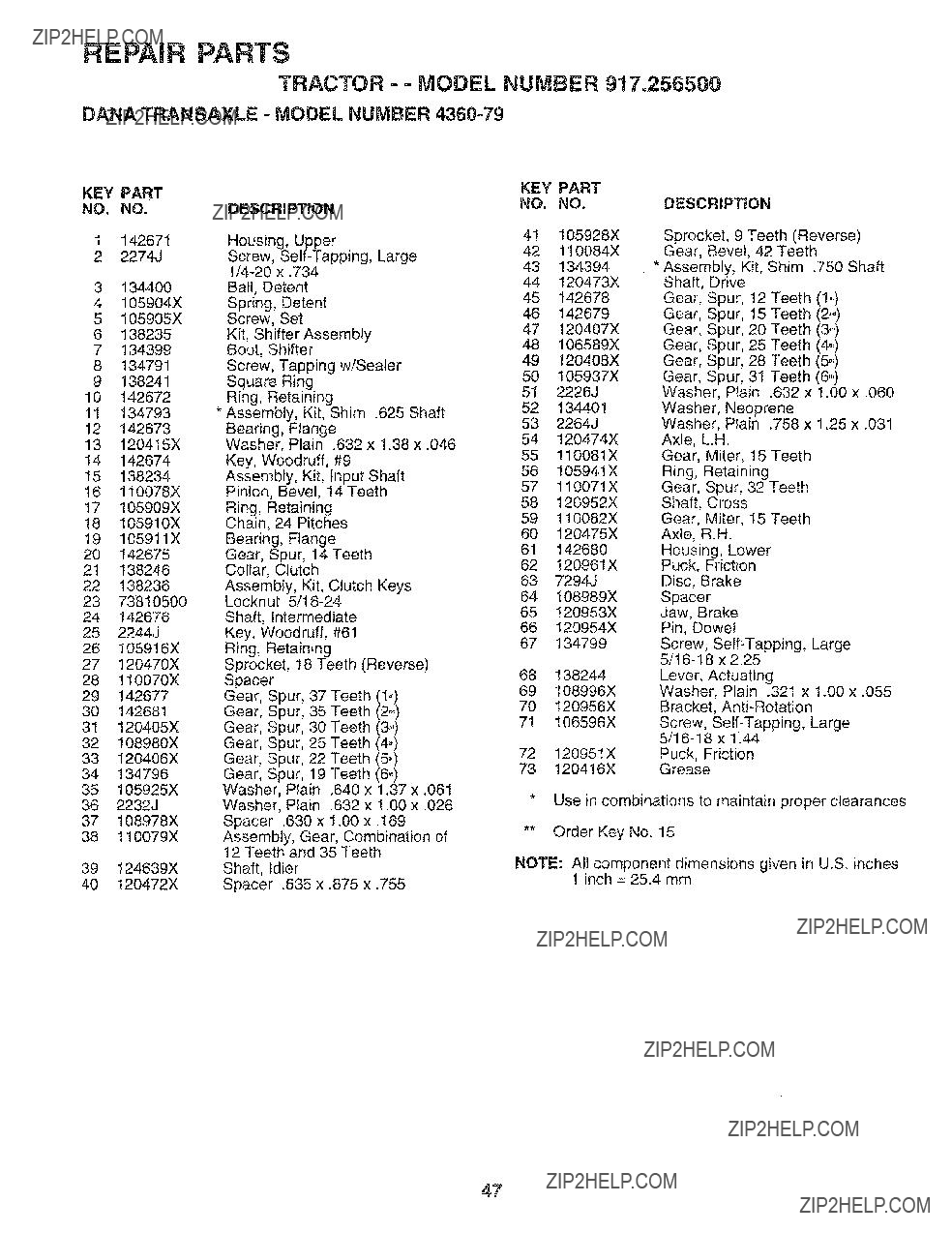
REPAIR PARTS
TRACTOR == MODEL NUMBER 917.256500
DANA TRANSAXLE = MODEL NUMBER
13120415X Washer, Plain .632 x 1.38 x .046
14142674 Key, Woodruff, #9
KEY PART NO. NO.
41105928X
42110084X
43134394
44120473X
45t42678
46t42679
47120407X
48106589X
49120408X
50105937X
512226J
52134401
532264J
54120474X
55110081X
56105941X
57110071X
58120952X
59110082X
60 120475X
61 142680
62 120961X
63 7294J
64 108989X
65120953X
66120954X
67 134799
68138244
69108996X
70 120956X
71 106596X
7212095IX
73120416X
DESCRiPTiON
Sprocket, 9 Teeth (Reverse)
Gear, Bevel, 42 Teeth
*Assembly, Kit, Shim .750 Shaft Shaft, Drive
Gear, S_ur, 12 Teeth (1o,) Gear, S_ur, 15 Teeth (2,,) Gear, S_ur, 20 Teeth (3,,) Gear, Sgur, 25 Teeth (4,,,) Gear, S_ur, 28 Teeth (5_) Gear, S:)ur, 31 Teeth (6_)
Washer Plain .632 x 1.00 ?? .060
Washer Neoprene
Washer Plain .758 x 1.25 x .031 Axle, L.H.
Gear, Miter, 15 Teeth Ring, Retaining
Gear, Spur, 32 Teeth Shaft, Cross
Gear, Miter, 15 Teeth Axle, R.H.
Housing, Lower Puck, Friction Disc, Brake
Spacer Jaw, Brake Pin, Dowel
Screw, Self,Tapping, Large
Lever, Actuating
Washer, Plain .321 x 1.00 x .055 Bracket,
Screw,
Puck, Friction Grease
12 Teeth and 35 Teeth
39 t24639X Shaft, Idler
40 120472X Spacer .635 x .875 x .755
*Use in combinations to maintain proper clearances
**Order Key No. 15
NOTE: All component dimensions given in U.S. inches 1 inch = 25.4 mm
47
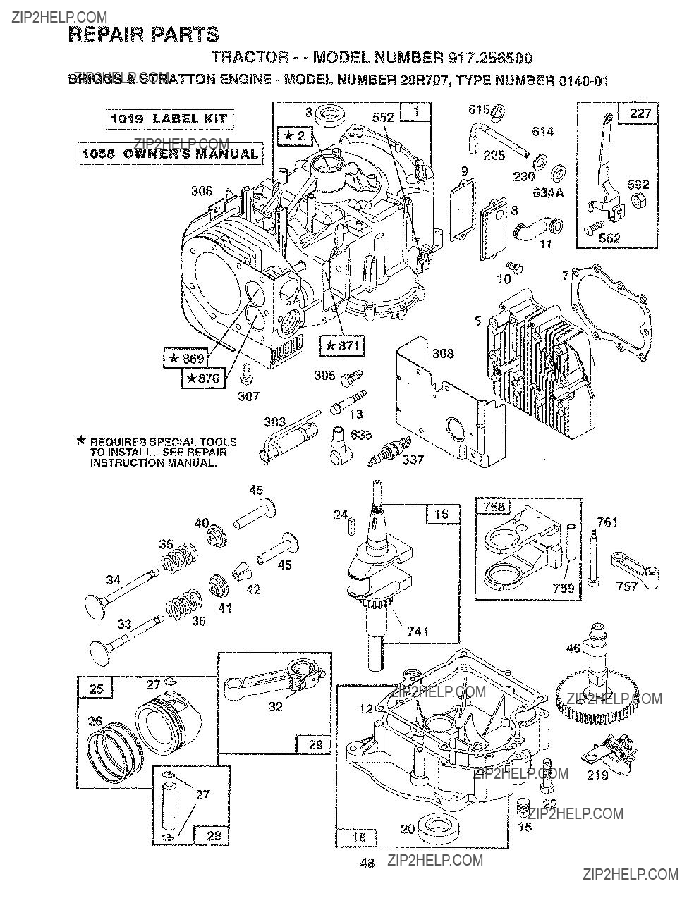
REPAIR PARTS
TRACTOR - - MODEL NUMBER 917.256500
BRIGGS & STRATTON ENGINE - MODEL NUMBER 28R707_ TYPE NUMBER
61s_
9 23o0_
306
8 634A
5
3O8
45
4
32
48

REPAIR PARTS
TRACTOR - - MODEL NUMBER 917.256500
BRIGGS & STRATTON ENGINE - MODEL NUMBER 28R707, TYPE NUMBER 0140=01
125
130
147 _] 108
_137
@ 138
164 _ 123
!42
REQUIRES SPECIAL TOOLS
TO INSTALL. SEE REPAIR
INSTRUCTION MANUAL.
523
224
872l
17!
I525
53;
535
646 _ 284A
49
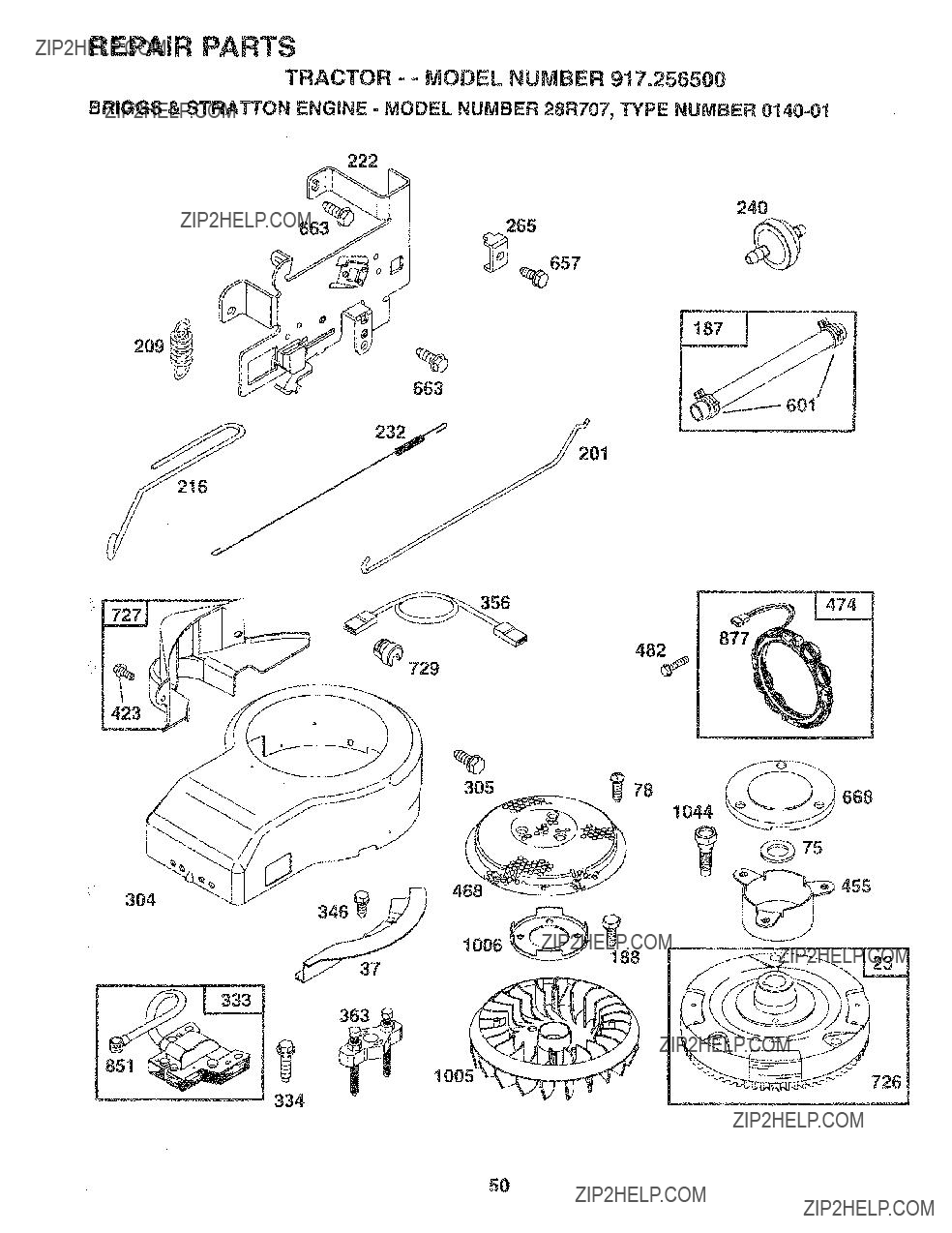
REPAIR PARTS
TRACTOR = - MODEL NUMBER 917.256500
BRIGGS & STRATTON ENGINE - MODEL NUMBER 28R707, TYPE NUMBER 0140=01
240
265
209
601
305_ 78
668
1044
75
455
_726
100,_
334
5O
REPAIR PARTS
TRACTOR - - MODEL NUMBER 917.256500
BRIGGS & STRATTON ENGINE - MODEL NUMBER 28R707, TYPE NUMBER
728
1090
311
803
544
51

FiEPAJR PARTS
TRACTOR - - MODEL NUMBER 917.256500
BRIGGS & STRATTON ENGHNE - MODEL NUMBER 28R707, TYPE NUMBER
52
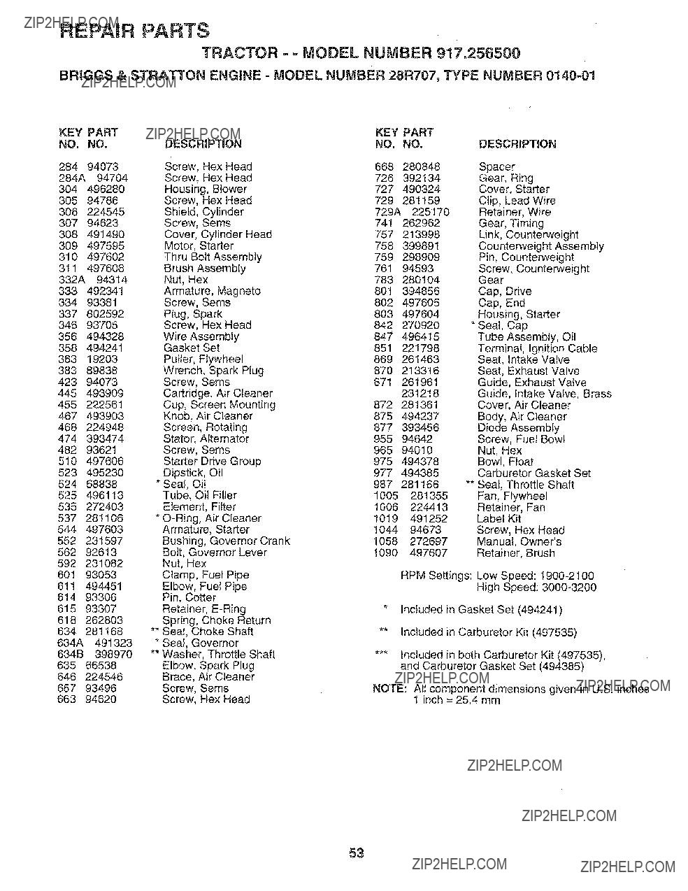
REPAIR PARTS
TRACTOR = = MODEL NUMBER 917.25{}500
BRtGGS & STRATTON ENGINE =MODEL NUMBER 28R707, TYPE NUMBER
53

SERVICE OTES
54

Z
0
m
,,<
CC
13.1
0
LLI
13.
O3
0
LL,,
O3
W
0
,,,,,,I
gO
0
Z
emma
::C:
0
U)
0
LI.,
LLI
0
m
::::)
t_
LLI
t_ r_
J
",r-
Z:
0/
a
/
z,,,_
<:T:
CL
O3
uJ 0
>,.,<
zO Oz
0
o/_
/
/
/
/ o
Z
/
/
!
/
o0

S IR8
OWNER'S
MANUAL
MODEL NO. 917.256500
IF YOU NEED
REPAIR SERVICE
OR PARTS:
FOR REPAIR SERVICE, CALL
THIS TOLL FREE NUMBER:
FOR REPLACEMENT PARTS
INFORMATION AND
ORDERING, CALL THIS
TOLL FREE NUMBER:
FOR CONSUMER ASSISTANCE
HOT LINE, CALL THIS
TOLL FREE NUMBER:
150661 Rev. 1 !&12.95 TR
??
13.5 HP IC
ELECTRIC START 42" MOWER
6 SPEED TRANSAXLE
LAWN TRACTOR
Each tractor has its own model number. Each engine has its own mode] number.
The mode] number for your tractor will be found on the model plate located under the seat.
The model number for your engine will be found on the blower housing of the engine,
All parts listed herein may be ordered from any Sears, Roebuck and Co. Service Center/Department and most Re - tail Stores.
WHEN ORDERING REPAIR PARTS, ALWAYS GIVE THE
FOLLOWING INFORMATION:
= PRODUCT - TRACTOR
??? MODEL NUMBER- 917.256500
= ENGINE MODEL NO. - 28R707, TYPE NO.
??? PART NUMBER
,, PART DESCRIPTION
Your Sears merchandise has added vatue when you consider Sears has service units nationwide staffed with
Sears trained technicians.., professional technicians specifically trained to insure that we meet our pledge to you, we service what we see
Printed in U:S.A.