OWNER'S

MANUAL

MODEL NO.

917.255590

Caution:

Read and follow

all Safety Rules and instructions

Before Operating

This Equipment

,Assembly

???Operation

. Customer Responsibilities

??? Service and Adjustment

?? Repair Parts

Sears, Roebuck and Coo, Chicago, JL 60684 U.S??A.

IMPORTANT: THIS CUTTING MACHINE IS CAPABLE OF AMPUTATING HANDS AND FEET AND THROWING OBJECTS,

FAILURE TO OBSERVE THE FOLLOWING SAFETY INSTRUCTIONS COULD RESULT IN SERIOUS INJURY OR DEATH,

L GENERAL OPERATmON

eRead, understand, and follow alt instructions in the manual and on the machine before starting,

Only allow responsible adults, who are familiar with the instructions, to operate the machine.

Clear the area of objects such as rocks, toys, wire, etc., which could be picked up and thrown by the blade,

oBe sure the area is clear of other people before mowing. Stop machine if anyone enters the area,

Never carry passengers.

Do not mow in reverse untess absolutely necessary. Always look down and behind before and while backing.

eBe aware of the mower discharge direction and do not point it at anyone. Do not operate the mower without either the entire grass catcher or the guard in place.

Slow down before turning.

Never leave a running machine unattended. Always turn off blades, set parking brake, stop engine, and remove keys before dismounting,

Turn off btades when not mowing.

Stop engine before removing grass catcher or unclogging chute.

Mow only in daylight or good artificial light.

Do not operate the machine while under the influence of alcohol or drugs.

Watch for traffic when operating near or crossing roadways,

Use extra care when loading or unloading the machine into a trailer or truck.

I1. SLOPE OPERATION

Slopes are a major factor related to loss-of-control and tipover

accidents, which can result in severe injury or death. All slopes require extra caution. If you cannot back up the slope or if you feel uneasy on it, do not mow it.

DO:

-Mow up and down slopes, not across.

o Remove obstacles such as rocks, tree limbs, etc.

o Watch for holes, ruts, or bumps. Uneven terrain could overturn the machine. Tall grass can hide obstacles.

???Use slow speed. Choose a low gear so that you will not have to stop or shift while on the slope.

I& CHILDREN

Tragic accidents can occur if the operator is not alert to th_ presence of children, Children are often attracted to the machin_

and the mowing activi_. Never assume that children will remair_ where you last saw them.

oKeep children out of the mowing area and under the watchfu! care of another responsible adult.

oBe alert and turn machine off if children enter the area.

Before and when backing, _ook behind and down for smali children.

Never carry children, They may fall off and be seriously injured or interfere with the safe machine operation.

Never allow cNdren to operate the machine.

Use extra care when approaching blind corners, shrubs, trees, or other objects that may obscure vision.

IV. SERVICE

oUse extra care in handling gasoline and other fuels. They are flammable and vapors are explosive.

Use only an approved container.

*Never remove gas cap or add fuel with the engine

running. Allow engine to coo_ before refueling. Do no_. smoke.

Never refuel the machine indoors.

Never store the machine or fuel container inside where there is an open flame, such as a water heater.

Never run a machine inside a closed area.

. Keep nuts and bolts, especiafiy blade attachment bolts, tight and keep equipment in good condition.

,Never tamper with safety devices. Check their proper operation regularly.

-Keep machine free of grass, leaves, or other debris build-up. Clean oil or fuel spillage. AtSow machine to cool before storing.

"Stop and inspect the equipment if you strike an object. Repair, if necessary, before restarting.

. Never make adjustments or repairs with the engine running.

oGrass catcher components are subject to wear, damage, and deterioration, which coutd expose moving parts or allow objects to be thrown. Frequently check components and replace with manufacturer's recommended parts, when neck. essary.

o Do not turn on slopes unless necessary, and then, turn slowly and gradually downhill, if possible.

???Do not mow near drop-offs, ditches, or embankments. The mower could suddenly turn over if a wheel is over the edge of a cliff or ditch, or if an edge caves in,

=Do not mow on wet grass. Reduced traction could cause sliding.

oDo not try to stabilize the machine by putting your foot on the ground.

CAUTaON: Amways disconnect spark

contact spark p_ug in order to prewnt plug wire and #face wire where it cannot accidental starting when setting up,

transporting, adjusting or making repairs,

CONGRATULATIONSon your purchaseof a Sears Tractor. tt has beendesigned,engineered and manu-

factured to give you the best possible dependability and performance.

Should you experience any problem you cannot easily remedy, please contact your nearest Sears Service

Center/Department. We have competent, well-trained technicians and the proper tools to service or repair this unit.

Please read and retain this manual. The instructions will enable you to assemble and maintain your unit properly. Always observe the "SAFETY RULES".

MODEL

NUMBER 917.255590

SERIAL

NUMBER

DATE OF PURCHASE

THE MODELAND SERIAL NUMBERS WILL BE FOUND

ON A PLATE UNDER THE SEAT.

YOU SHOULD RECORD BOTH SERIAL NUMBER AND

DATE OF PURCHASE AND KEEP IN A SAFE PLACE

FOR FUTURE REFERENCE.

MAWNTENANCE AGREEMENT

A Sears Maintenance Agreement is available on this prod- uct. Contact your nearest Sears store for details.

CUSTOMER RESPONSIBALtTIES

???Read and observe the safety rules.

Follow a regular schedule in maintaining, caring for and using your unit.

???Follow the instructions under "Customer Responsibili- ties" and "Storage" sections of this owner's manual.

PRODUCT SPEC FmCATIONS

WARNING: This unit is equipped with an internal combus- tion engine and should not be used on or near any unim- proved forest-covered, brush-covered or grass-covered land unless the engine's exhaust system is equipped with a spark arrester meeting applicable local or state laws (if any). tf a spark arrester Jsused, it should be maintained in effective working order by the operator.

In the state of California the above is required by law

(_Section 4442 of the California Public Resources Code). Other states may have similar laws. Federal taws apply on federal lands. A spark arrester for the muffler is available through your nearest Sears Authorized Service Center (See REPAIR PARTS section of this manual).

LIMITED TWO YEAR WARRANTY ON ELECTRIC START RIDING EQUIPMENT

For two (2) years from the date of purchase, if this riding equipment is maintained, lubricated and tuned up according to the instructions in the owner'smanual, Sears will repair or replace, free of charge, any parts found to be defective in material or

workmanship,

This Warranty does not cover:

???Expendable items which becomeworn during normal use, such as blades, spark plugs, air cleaners and belts.

???Tire replacement or repair caused by punctures from outside objects, such as naits, thorns, stumps, or glass.

oRepairsnecessary because of operator abuse, negligence, improper storage or accident or the failure to maintain the equipment according to the instructions contained in the owner'smanual,

Riding equipment used for commercial or rental purposes.

LiMiTED 90 DAY WARRANTY ON BATTERY

For 90 days from date of purchase, if any battery included with this riding equipment proves defective in material or workmanship and our testing determines the battery wil_not hold a charge, Sears will replace the battery at no charge,

WARRANTY SERVICE IS AVAILABLE BY RETURNING THE RIDING EQUIPMENT TO THE NEAREST SEARS SERVICE CENTER/DEPARTMENT tN THE UNITED STATES.

This Warranty gives you specific legal rights, and you may also have other rightswhich may vary from state to state.

SEARS, ROEBUCK AND CO., Di731CR-W, SEARS TOWER, CHICAGO, ILLINOIS 60684

3

TABLE OF CONTENTS

raND

E

4

ACCESSORIES AN ATTACHMENTS

These accessories and attachments were available when the unit was purchased. They are a_so available at most Sears retail outfets,

catalog and service centers. Most Sears stores can order these items for you when you provide the model number of your tractor.

PERFORMANCE

Sears offers a wide variety of attachments that fit your vehicle. Many of these are listed below with brief explanations of how they can help you. This list was current at the time of publication; however, it may change in future years - more attachments may be added, changes may be made in these attachments, orsome may no longer be available orfit your model. ContactyournearestSearsstorefortheaccessotie$

and attachments that are available for your unit,

Most of these attachments do not require additional hitches or conversion kits (those that do are indicated) and are designed for easy attaching and detaching.

PERMANEX BAGGER tats you collect grass clippings and leaves for a healthier, nearer looking lawn. Two Permanex containers hold 30-gailon plastic bags.

LAWN SWEEPERS let you collect grass clippings and leaves.

LAWN VACS for powerful collection of heavy grass clippings and leaves. Wand attachment to pick up debris in hard-to-reach

places.

CARTS make hauling easy. Variety of sizes available.

ROLLER for smoother lawn surface. 36-inch wide, 18-inch diameter water-tight drum holds upto390 Ibs. ofweight. Rounded

edges prevent harm to turf. Adjustable scraper automatically cleans drum.

SPREADER!SEEDERS make seeding, fertilizing, and weed kiIling easy. Broadcast spreaders are also useful for granular de-icers and sand.

CORING AERATOR takes small plugs out of soil to allow mois- ture and nutrients to reach grass roots. 36-inch swath, 24 hardened steel coring tips. 150 lb, capacity weight tray.

AERATOR promotes deep root growth for a healthy lawn. Ta- pered 2,5-inch steel spikes mounted on 10-inch diameter discs puncture holes in soil at close intervals to let moisture soak in. Steel weight tray for increased penetration.

MULCH RAKE/DETHATCHER !oosens soi! and flips thatch and matted leaves to lawn surface for easy pickup. Twenty spring tine teeth. Useful to prepare bare areas for seeding. Available for front or rear mounting,

SPRAYERS use 12-volt DC electric motor that connects to the tractor battery or other 12-vott source. Includes booms for automatic spraying when putling, and hand held wand for spot spraying. Wand has adjustable spray pattern. For applying herbicides, insecticides, fungicides, and fiquid fertilizers,

SNOW BLADE for snow removal only. 14-inch high, 42-inch wide blade clears 38-inch path when angled left or right, Raises, iowers with side lever. Adjustabie skids; replaceable, reversible scraper bar. (Use with tire chains, wheel weights, or rear drawbar weight.)

SNOWTHROWER has 40-inch swath, Drum4ype auger handles powdery and wet/heavy snow. Mounts easily with simple pin arrangement. Discharge chute adjusts from tractor seat. (;-inch diameter spout discharges snow 10 to 50 feet. Lift controlled at tractor seat. (Use with chains, wheel weights, or rear drawbar weight.)

TIRE CHAINS are heavy duty; closely spaced extra-large cross links give smooth ride, outstanding traction.

WHEEL WEIGHTS for rear wheels provide needed traction for snow removal or dozing heavy materials. In pairs. (30 Ibs. each.)

TRACTOR CAB has heavy duty vinyl fabric over tubular steel frame, ABS plastic top; clear plastic windshield offers 360 degree visibility. Hinged metal doors with catch. Keeps operator warm and dry. Remove vinyl and windshields for use as sun protector in summer. (Catalog only.)

Optional accessories for tractor cab: tinted/tempered solid

safety glass windshield with hand operated wiper; 12-volt amber caution light for mounting on cab top, (Catalog only.)

TRACTOR COVER protects tractor from weather. Made of Evolution 3 fabric (water-repellent, extremely breathable, light weight, soft, non-abrasive, pliable in all temperatures, durable, stain/tear/puncture resistant, will not shrink or stretch.) (Catalog only.)

5

CONTENTS OF HARDWA PACK

\

(1) Locknut 3/8-24

(1) 2_3/8" Dia. Washer

(1) Washer 17/32 x 1-3/16 x 12 Ga.

@

(2) Hex Bolts 1/4 - 20 x 3/4

(2) Hex Nuts 1/4- 20

z z

(2) Lock Washers I/4

(2) Washers 9/32 x 5/8 x 16 Ga.

Seat

Battery acid

l'

Parts bag contents not shown full size

6

ASSE BLY

Utility knife

When right and left hand is mentioned in this manual, it means when you are in the operating position (seated behind the steering wheel).

TO REMOVE UNIT FROM CARTON

UNPACK CARTON

-Remove all accessible loose parts and parts cartons from carton (See page 6).

???Cut along dotted lines on carton, from top to bottom, all four corners of carton and lay panels flat.

???Check for any additional loose parts or cartons and remove.

BEFORE ROLMNG UNIT OFF SKtD

ATTACH STEE!RJNG WHEEL (See Fig, 1)

o Slide the steering bushing over the steering shaft.

,Raise steering shaft forward until screw holes in dash line up with steering bushing. Install two (2) sheet metal screws and tighten securely.

o Position steering boot over steering shaft.

,Place tabs of steering boot over slots in dash and push down to secure.

-Slide steering wheel adapter onto upper steering shaft.

,Position front wheels of the tractor so they are pointing straight forward.

,Position steering wheel so cross bars are horizontal (left to right) and slide onto adapter.

???Assemble large flat washer and 3/8-24 hex fockn ut and tighten securely.

??Snap insert into center of steering wheel.

o Remove protective plastic from tractor hood and grill.

IMPORTANT; CHECK FOR AND REMOVE ANY

STAPLES IN SKID THAT MAY PUNCTURE TIRES WHERE

UNIT IS TO ROLL OFF SKID.

(See Fig. 6)

,Raise attachment lift lever to its highest position.

,Release parking brake by depressing clutch/brake pedal.

o Pull freewheel knob up to disengage transmission.

o Roll unit backwards off skid.

oRemove banding holding discharge guard up against tractor.

STEERING

BOOT

STEERING

BUSHING

STEERING SHAFT

(SHiPPiNG

POSiTiON)

STEERING SHAFT

(ASSEMBLY POSITION)

FIG. 1

7

ASSE BLY

HOW TO SET UP YOUR TRACTOR

PREPARE BAKERY (SeeFig,21

CAUTION: Wear eye a_d face shield.

Wash hands or c_othing _rnmedlately if accidentally in contact with battery acid.

Do not smoke. Fumes from charged battery acid are e??p_osiveo

Read the instructions included with the battery vent ??apso Always wear gloves,

c_othing and goggles to protect your hands_ skin and eyes.

Your unit has a battery charging system which is sufficient

for normal use. However, periodic charging of the battery with an automotive charger writ extend its life.

o See instructions packed with vent caps in parts bag.

oFil! battery with acid. Fill each celt until it reaches the bottom of the vent wetIs. Do not overfill.

Allow battery to stand and settle for at least thirty minutes. After standing, check the level of acid. if beiow the vent wells, add more acid until the correct level is reached.

_MPORTANT: TO MAXIMIZE THE UFE OF YOUR

BATTERY, iT IS NECESSARY THAT THE BATTERY BE

CHARGED BEFORE USE. FAILURE TO CHARGE

BATTERY CAN RESULT iN A SHORTENED BATTERY LIFE.

oCharge battery at a rate of 6 amperes for ! hour. Use a 12 volt battery charger. Observe all safety precautions required for battery charging.

oCheck the acid levet after the battery is charged. If the acid has fallen below the correct level, add distilled or iron free water.

ohstalt the vent caps to cover the vent wells. Wash the top of the battery with water to remove any acid, then w_pe dry.

oCheck battery case for leakage to make sure that no damage has occurred in handling.

???Dispose of excess battery acid. Neutralize acid for disposal by adding it to four inches of water in a five gallon plastic container. Stir with a wooden or plastic paddle while adding baking soda until the addition of more soda causes no more foaming.

o Follow instructions on how to instalI battery.

_NSTALL SEAT (See Fig, 3}

Adjust seat before tightening adjustment bolt.

o Remove cardboard packing on seat pan,

??P_ace seat on pan and assemble shoulder bolt.

???Assemble adjustment bolt, tock washer and flat washer loosely. Do not tighten,

???Tighten shoulder bolt securely.

oLower seat into operating position and sit on seat.

Slide seat until a comfortable position is reached which

allows you to press clutch/brake pedal all the way down (See Fig. 6).

???Get off seat without moving its adjusted poskion.

???Raise seat and tighten adjustment bolt securely.

FLAT WASHER

/

ADJUSTMENTLOCK WASHER

BOLT

FIG. 3

CHECK TIRE PRESSURE

The tires on your unit were overinflated at the factory for shipping purposes. Correct tire pressure is important for best cutting performance.

???Reduce tire pressure to PSI shown in "PRODUCT SPECIFICATIONS" on page 3 of this manual.

CHECK DECK LEVELNESS

For best cutting results, mower housing should be properly leveled. See "TO LEVEL MOWER HOUSING" in the

Service and Adjustments section of this manual.

CHECK FOR PROPER POS T ON OF ALL

BELTS

See the figures that are shown for replacing motion and mower blade drive belts in the Service and Adjustments section of this manual. Verify that the be!ts are routed correctly.

CHECK BRAKE SYSTEM

ASS LY

iNSTALL BATTERY (See Figs. 4 & 5)

............ i

CAUTION: Do not short battery termi-

meta_ bracelets, wristwatch bands, rings,hale. Beforeetc. installing battery, remove

Positive termina_ must be connected first to prevent sparking from accideno tat grounding.

. Lift seat to raised position.

,Open battery box door.

*Lower battery into battery box with battery terminals toward front of unit.

,Be sure battery drain tube is attached to battery box.

oFirst connect RED battery cabfe to positive (+) battery terminal with hex bolt, flat washer, lock washer and hex nut as shown. Tighten securely??

*Connect BLACK grounding cable to negative (-) bat, tery terminal with remaining hex bolt, flat washer, lock washer and hex nut?? Tighten securely.

o Close battery box door.

Open battery box door for:

oinspection for secure connections (to tighten hard- ware).

o Inspection for corrosion.

,Testing battery,

,Jumping (if required). Periodic charging

BATTERY

BOX DOOR

FLAT

WASHER

HEX \_\

BOLT

POSITIVE (+) TERMINAL

VENT CAPS

FIGo5

/ CHECKMST

BEFORE YOU OPERATE AND ENJOY YOUR NEW

TRACTOR, WE WISH TO ASSURE THAT YOU RECEIVE THE BEST PERFORMANCEAND SA TISFACT"iON FROM

THIS QUALITY PRODUCT.

PLEASE REVIEW THE FOLLOWING CHECKLIST:

,/ All assembly instructions have been completed.

??" No remaining loose parts in carton??

,/ Battery is properly prepared and charged. (Minimum 1 hour at 6 amps).

,/ Seat is adjusted comfortably and tightened securely.

,/ All tires are properly inflated, (For shipping purposes, the tires were over-inflated at the factory).

???" Be sure mower deck is properly leveled side-to-side/ front-to-rear for best cutting results. (Tires must be properly inflated for leveling).

??' Check mower and drive belts. Be sure they are routed properly around pulleys and inside all belt keepers.

_z Check wiring, See that all connections are still secure and wires are properly clamped.

WHILE LEARNING HOW TO USE YOUR TRACTOR, PAY EXTRA ATTENTION TO 7:HE FOLLOWlNG IMPORTANT

ITEMS:

,/ Engine oil is at proper level,

./ Fue! tank is filled with fresh, dean, regular unleaded gasoline.

??" Become familiar with all controls _ their !ocation and function. Operate them before you start the engine.

,/ Be sure brake system is in safe operating condition,

........ i

z

OPERATION

}<NOW YOUR TRACTOR

READ THiS OWNER'S MANUAL AND SAFETY RULES BEFORE OPERATING YOUR TRACTOR

Compare the illustrations with your tractor to familiarize yourself with the locations of various controls and adjustments. Save this manual for future reference.

ATTACHMENT CLUTCH LEVER

LIGHT SWITCH

THROTTLE/CHOKE

CONTROL

LIFT LEVER PLUNGER

ATTACHMENT LIFT LEVER

[l

MOTION CONTROL LEVER

FREEWHEEL CONTROL

FiG. 6

Sears tractors conform to the safety standards of the American National Standards institute.

ATTACHMENT CLUTCH LEVER: Used to engage the

mower biades, or other attachments mounted to your tractor.

LIGHT SWITCH: Turns the headlights on and off.

THROTTLE/CHOKE CONTROL: Used for starting and controlling engine speed.

CLUTCH/BRAKE PEDAL; Used for declutching and braking the tractor and starting the engine.

PARKING BRAKE: Locks clutch/brake pedal into the brake position.

MOTION CONTROL LEVER: Selects the speed and di-, rection of tractor.

ATTACHMENT LIFT LEVER: Used to raise, lower, and adjust the mower deck or other attachments mounted to your tractor,

UFT LEVER PLUNGER: Used to release attachment lift lever when changing its position.

IGNITION SW_TCH: Used for starting and stopping the engine.

FREEWHEEL CONTROL: Disengages transmission for pushing or slowly towing the tractor with the engine off.

10

OPERATION

......... i

The operation of any tractor can result in foreign objects thrown into the eyes, which can result in severe eye damage. Always wear safety glasses or eye shields while operating your tractor or performing any adjustments or repairs. We recommend wide vision safety mask for over the spectacles or standard safety g_asses, available at Sears Retail or Catalog stores.

HOW TO USE YOUR TRACTOR

TO SET PARKING BRAKE (See Fig. 7)

Your unit is equipped with an operator presence sensing switch. When engine is running, any attempt by the operator to leave the seat without first setting the parking brake wilt shut off the engine.

. Depress clutch/brake pedal into full "BRAKE" position and hold.

Place parking brake lever in "ENGAGED" position and release pressu refrom cfutchibrake pedal. Pedal should remain in "BRAKE" position. Make sure parking brake wilt hold vehicle secure.

ENGINE -

Move throttle control to "SLOW" position.

Turn ignition key to "OFF" position and remove key. Always remove key when leaving vehicle to prevent unauthorized use.

,Never use choke to stop engine.

NOTE: Under certain conditions when unit is standing idle with the engine running, hot engine exhaust gases may cause "browning" of grass. To eliminate this possibility, always stop engine when stopping unit on grass areas.

STOPPING (See Fig, 7)

MOWER BLADES -

Move attachment clutch lever to "DISENGAGED" po- sition.

GROUND DRIVE -

??? Depress clutch/brake pedal into ful! "BRAKE" position.

,Move motion control lever to "NEUTRAL" position.

iMPORTANT; THE MOTION CONTROL LEVER DOES

NOT RETURN TO "NEUTRAL" POSITION WHEN THE

CLUTCH/BRAKE PEDAL IS DEPRESSED.

TO USE THROTTLE CONTROL (See Fig. 7)

Always operate engine at full throttle.

???Operating engine at less than full throttle reduces the battery charging rate and the engine cooling air flow.

oFull throttle offers the best bagging and mower per- formance.

TO MOVE FORWARD AND BACKWARD (See

Fig. 6)

The direction and speed of movement is controlled by the motion control lever.

???Start tractor with motion control lever in "NEUTRAL" position.

,Release parking brake and clutch/brake pedal. Slowly move motion control lever to desired position.

TO ADJUST MOWER CUTTING H_I_T l_,_,= Fig. 6)

The position of the attachment lift lever determines the cutting height,

o Grasp lift lever,

. Press plunger with thumb and move lever to desired position.

The cutting height range is approximately 1-t/2" to 4". The heights are measured from the ground to the blade tip with the engine not running. These heights are approximate

and may vary depending upon soil conditions, height of grass and types of grass being mowed,

oThe average lawn should be cut approximately 2-t/2

inches during the cool season and over 3 inches during hot months, For healthier and better looking lawns, mow often and after moderate growth,

oFor best cutting performance, ..qr_c_ov_r 6 inches in height should be mowed twice. Make the first cut relatively high; the second to desired height.

11

OPEFIATIO

TO OPERATE MOWER (See Fig. 8)

Your unit is equipped with an operator presence sensing switch. Any attempt by the operator to leave the seat with the engine running and the attachment clutch engaged will shut off the engine.

???Select desired height of cut.

oEngage mower by slowly moving attachment clutch lever to "ENGAGED" position.

oTO STOP MOWER - Move attachment clutch lever to "DISENGAGED" position.

LOW

POSJTtON

DISCHARGE GUARD

FIG, 8

TO OPERATE ON HILLS

hills with slopes greater than 15 ?? and

???Choose the slowest speed before starting up or down hills.

o Avoid stopping or changing speed on hills.

???if slowing is necessary, move throttle control lever to slower position.

,If stopping is absolutely necessary, push clutch/brake

pedal quickly to brake position and engage parking brake.

Move motion control lever to "NEUTRAL" position.

IMPORTANT: THE MOTION CONTROL LEVER DOES

NOT RETURN TO "NEUTRAL" POSITION WHEN THE

CLUTCH/BRAKE PEDAL IS DEPRESSED.

oTo restart movement, slowly release parking brake and clutch/brake pedal.

???Slowly move motion control lever to slowest setting.

???Make all turns slowly.

TO TRANSPORT

oPull freewheel control knob up to disengage transmis- sion (See Fig. 6).

,When pushing or towing your unit, be sure motion control lever is in "NEUTRAL" position??

???Raise attachment lift control to highest position.

,Do not push or tow unit at more than five (5) MPH.

BEFORE STARTING THE ENGINE

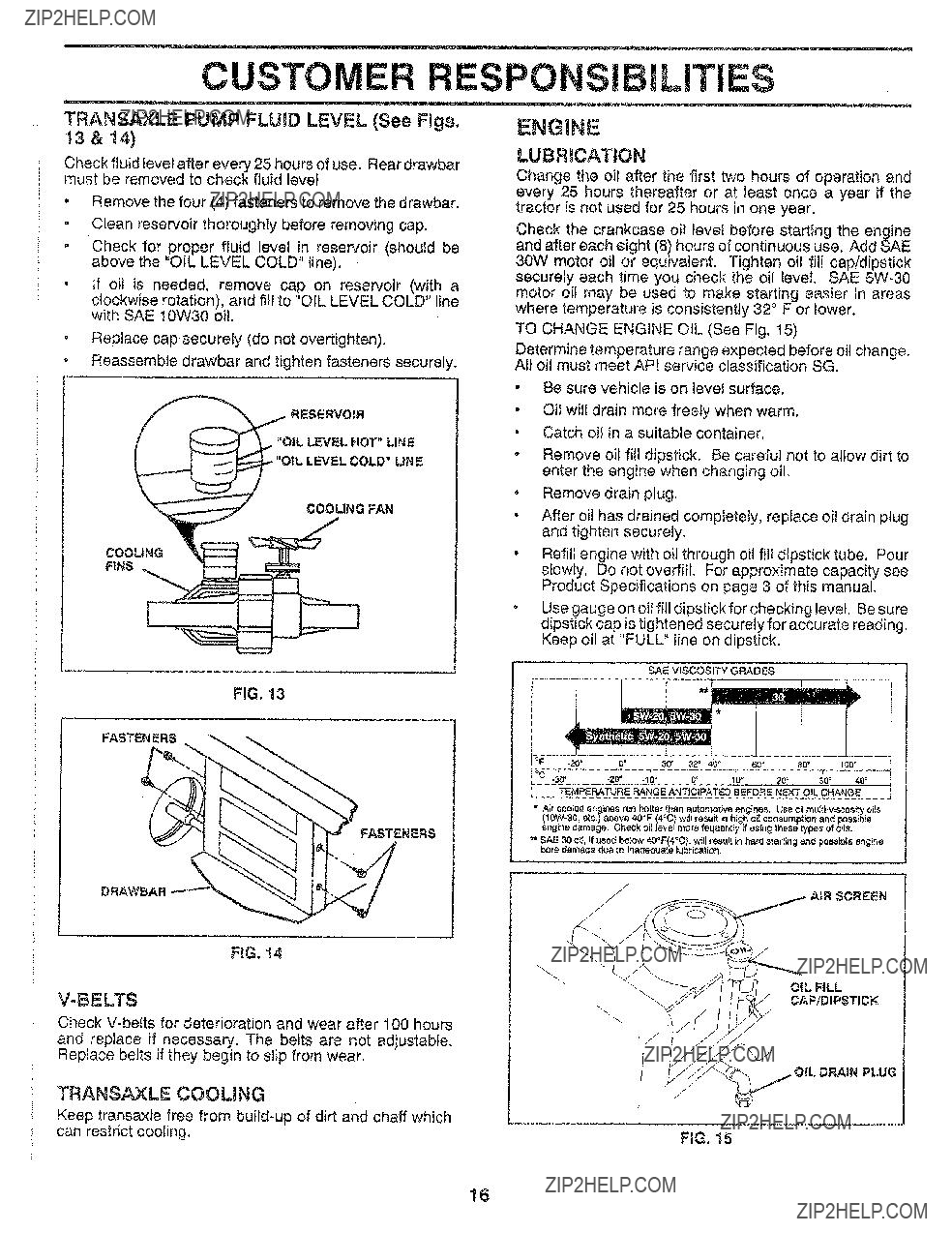
CHECK ENGINE OIL LEVEL (See Fig. 15)

???The engine in your unit has been shipped, from the factory, already filled with summer weight oil.

o Check engine oil with unit on level ground.

???Remove oi! fill dipstick and wipe clean, replace and screw cap tight, wait for a few seconds, remove and

read oi! level. If necessary, add oil until "FULL" mark on dipstick is reached. Do not overfill.

???For cold weather operation you should change oil for easier starting (see "OIL VISCOSITY CHART" in the Customer Responsibilities section of this manual).

,To change engine oil, see the Customer Responsibilities section in this manual.

ADD GASOLINE

???Fill fuel tank. Use fresh, clean, regular unleaded gasoline. (Use of leaded gasoline will increase carbon and lead oxide deposits and reduce vatve life).

iMPORTANT: WHEN OPERATING IN TEMPERATURES

BELOW 32??F(0??C), USE FRESH, CLEAN WINTER GRADE

GASOLINE TO HELP INSURE GOOD COLD WEATHER

STARTING.

WARNING: Experience indicates that alcohol blended fuels (called gasohol or using ethanol or methanol) can attract moisture which leads to separation and formation of acids during storage. Acidic gas can damage the fuel system of an engine while in storage. To avoid engine problems, the fue! system should be emptied before stor- age of 30 days or longer. Drain the gas tank, start the engine and let it run until the fuel lines and carburetor are emptyh Use fresh fuel next season. See Storage instruc- tions for additional information. Never use engine or carburetor cleaner products in the fuel tank or permanent damage may occur.

CAUTION: Fill to bottom of gas tank filler neck, Do not overfill Wipe off any spiWed oil or fuel Do not store, spill or use gasoline neBr an open flame??

OPERATIO

.......

......... ! z z

TO START ENGINE (See Fig. 7)

When starting engine for the first time or if engine has run out of fuel, it wil! take extra cranking time to move fuel from the tank to the engine.

. Depress the clutch/brake pedal and set the parking brake,

???Place motion control lever in "NEUTRAL" position.

???Move attachment clutch to "DISENGAGED" position.

Move throttle control lever to "CHOKE" position for cold engine start, For warm engine start, move throttle control to "FAST" position,

???Turn ignition key clockwise to "START" position and release key as soon as engine starts. Do not run starter continuously for more than fifteen seconds per minute, If engine does not start after several attempts, move throttle control to "FAST" position, wait a few minutes and try again.

???When engine starts, move throttle control to desired position.

. Allow engine to warm up for a few minutes before engaging drive or attachment clutch,

NOTE: If at a high altitude (above 3000 feet) or in cold temperatures (below 32 ?? F), the carburetor fuel mixture may need to be adjusted for best engine performance.

See "TO ADJUST CARBURETOR" in the Service and Adjustments section of this manual.

MOWING TIPS

- Tire chains cannot be used when the mower hous- ing is attached to unit.

???Mower should be properly leveled for best mowing performance, See "TO LEVEL MOWER HOUSING" in the Service and Adjustments section of this manual.

???Use the runner on the right hand side of mower as a guide. The blade cuts approximately an inch outside the runner (See Fig. 8),

,The left hand side of mower should be used for trim- ming.

Drive so that clippings are discharged onto the are_ that has been cut. Have the cut area to the right o the machine. This will result in a more even distri- bution of clippings and more uniform cutting.

When mowing large areas, start by turning to th( right so that clippings will discharge away frorr shrubs, fences, driveways, etc. After one or tw_ rounds, mow in the opposite direction making lef hand turns until finished (See Fig. 9).

\J

FIG, 9

,tf grass is extremely tall, it should be mowed twic_ to reduce toad and possible fire hazard from drie_: clippings. Make first cut relatively high; the secon( to the desired height.

,Do not mow grass when it is wet. Wet grass wil plug mower and leave undesirable clumps. AI!ov, grass to dry before mowing,

oAlways operate engine at full throttle when mowin( to assure better mowing performance and prope discharge of material. Regulate ground speed b_ selecting a tow enough gear to give the mowe cutting performance as well as the quality of cu desired.

When operating attachments, select a ground spee( that wilt suit the terrain and give best performance o the attachment being used.

13

CUSTOM ESPO ILITIES

.......... i

GENERAL RECOMMENDATIONS

The warranty on this vehicle does not cover items that have been subjected to operator abuse or negligence. To

receive full vatue from the warranty, operator must main- tain unit as instructed in this manual.

Some adjustments will need to be made periodically to properly maintain your unit.

AJtadjustments in the Service and Adjustments section of this manuat should be checked at least once each season.

,Once a year you should replace the spark plug, clean or replace air filter, and check blades and belts for

wear. A new spark plug and clean air fiJter assure proper air-fuel mixture and help your engine run better and last longer.

BEFORE EACH USE

???Check engine oil leveE.

,Check brake operation.

o Check tire pressure.

???Check for loose fasteners.

C

PUMP FLUID

(_ SAE t0W30 MOTOR OIL API - SG

(_ GENERAL PURPOSE GREASE

??REFER TO CUSTOMER RESPONSIBJLITi,_S "ENGINE" SECTION

iMPORTANT: DO NOT O_L OR GREASE THE PIVOT POINTS

WHICH HAVE SPECIAL NYLON BEARINGS. VISCOUS LUBRI-

CANTS WILL ATTRACT DUST AND DIRT THAT WILL SHORTEN THE LIFE OF THE SELF-LUBRICATiNG BEARINGS. IF YOU

t4 FEEL THEY MUST BE LUBRICATED, USE ONLY A DRY, POW_

DERED GRAPHITE TYPE LUBRICANT SPARINGLY.

CUSTO RESPONSi L ES

....... i

TRACTOR

Always observe safety rules when performing any main- tenance.

BRAKE OPERATION

If unit requires more than six (6) feet stopping distance at high speed in highest gear, than brake must be adjusted. (See "TO ADJUST BRAKE" in Service and Adjustments section of this manual).

TIRES

oMaintain proper air pressure in all tires (See "PROD- UCT SPECIFICATIONS" on page 3 of this manual),

oThe btade can be sharpened with a file or on a grindin1? wheel. Do not attempt to sharpen while on the mower.

-To check blade balance, you wili need a 5/8" diamete__ steel bolt, pin, or a cone balancer. (When using a cone balancer, follow the instructions supplied with bal

anoer).

Slide blade on to an unth readed portion of the steel boit

or pin and hold the bolt or pin parallel with the ground, If blade is balanced, it should remain in a horizontai position, tf either end of the blade moves downward, sharpen the heavy end until the blade is balanced.

NOTE: Do not use a nail for balancing blade, The lobes of the center hole may appear to be centered, but are not.

//

-Avoid stumps, stones, deep ruts, sharp objects and other hazards that may cause tire damage.

BLADE CARE

For best results mower blades must be kept sharp. The blades can be sharpened with a file or on a grinding wheel. We suggest they be sharpened or replaced after every 25 hours of mowing, Check blades more often if mowing in sandy conditions.

???Do not attempt to sharpen blades while they are on the mower.

???Replace bent or damaged blades.

BLADE REMOVAL (See Fig. 10)

,Raise mower to highest position to allow access to blades.

FiG, 11

BATTERY (See Fig, 12)

Your unit has a battery charging system which is sufficient for normal use. However, periodic charging of the battery with an automotive charger will extend it'slife.

oAcid solution level in each battery cell should be ever_ with bottoms of vent wetls. Add only distilled or iron free water if necessary. Do not overfill.

Remove hex bolt, lock washer and flat washer securing blade.

CUSTO RESPONSI LITIES

TRANSAXLE PUMP FLUUD LEVEL (See Figs,

t3 & 14)

Check fluid level after every 25 hours of use, Rear drawbar must be removed to check fluid level??

+Remove the four (4) fasteners to remove the drawbar.

??? Clean reservoir thoroughly before removing cap.

+Check for,proper fluid+ level in reservoir (should be above the OiL LEVEL COLD" line).

-If oil is needed, remove cap on reservoir (with a

clockwise rotation), and fill to "OIL LEVEL COLD" line with SAE 10W30 oil.

. Replace cap securely (do not overtighten).

???Reassemble drawbar and tighten fasteners securely.

ENGINE

LUBRMCATION

Change the oil after the first two hours of operation and every 25 hours thereafter or at least once a year if the tractor is not used for 25 hours in one year,

Check the crankcase oil level before starting the engine and after each eight (8) hours of continuous use. Add SAE 30W motor oil or equivalent. Tighten oil fi!t cap/dipstick securely each time you check the oil level, SAE 5W-30 motor oil may be used to make starting easier in areas where temperature is consistently 32 ?? F or lower.

TO CHANGE ENGINE OIL (See Fig+ 15)

Determine temperature range expected before oil change. All oil must meet API service classification SG.

+Be sure vehicle is on level surface.

??? Oil will drain more freely when warm.

, Catch oil in a suitable container.

+ Remove oil fill dipstick. Be careful not to allow dirt to enter the engine when changing oiL

+ Remove drain plug.

COOLING FAN

- After oil has drained completely, replace oil drain plug and tighten securely.

??? Refill engine with oil through oil fill dipstick tube, Pour slowly. Do not overfil!. For approximate capacity see Product Specifications on page 3 of this manual,

" Use gauge on oi! fill dipstick for checking level. Be sure dipstick cap is tightened securely for accurate reading. Keep oil at "FULL" fine on dipstick.

Check V-belts for deterioration and wear after 100 hours

and replace if necessary. The belts are not adjustable,

TRANSAXLE COOUNG

OIL DRAIN PLUG

16

..... i

z

CUSTO E RESPONSI

Your engine will not run properly and may be damaged by using a dirty air filter, Cfean the foam pre-cleaner element after every 25 hou rs of operation, more often if used in very dusty, dirty conditions.

o Remove knob and cover.

o Remove cartridge nut and replace cartridge.

o Reassemble and tighten securely.

NOTE.: Do not attempt to clean or oii the paper cartridge. Replace paper cartridge once a year or after every I00 hours of operation, more often if used in very dusty, dirty conditions.

,Wash foam pre-cteaner in liquid detergent and water.

,Wrap foam pre??cleaner in cloth and squeeze dry.

LtTtES

BLOWER HOUSING

SCREWS

oLightly coat foam preocleaner with clean engine oil.

Squeeze in towel to remove excess oit. Do not satu- rate.

, InstaII foam pre-cleaner over paper cartridge.

-Reassemble cover and secure with knobs.

ENGINE COOMNG FIiNS

FiG. t7

MUFFLER

Inspect and replace corroded muffler and spark arrester (il equipped) as it could create a fire hazard and/or damage.,

COVER

AIR SCREEN (See Fig. I5)

The engine air screen must be kept free of dirt and chaff to prevent engine damage from overheating. Clean with a wire brush or compressed air to remove dirt and stubborn dried gum fibers.

SPARK PLUGS

Replace spark plugs at the beginning of each mowin!; season or after every 100 hours of use, whichever come_ first. Spark plug type and gap setting is shown in "PROD ._ UCT SPECIFICATIONS" on page 3 of this manual.

IN-LINE FUEL FBLTER (See Fig. 18)

Fuel filter should be replaced once each season, if fue_filte_ becomes clogged, obstructing fuel flow to carburetor, re,, placement is required,

=With engine coot, remove filter and plug fuel ]in<; sections,

,Place new fuel filter in position in fuel line.

oBe sure there are no fuel line leaks and clamps arc properly positioned,

o Immediately wipe up any spilled gasoline,

FILTER

ENGINE COOUNG FINS (See Fig. t7)

Remove any dust, dirt or oil from engine cooling fins to prevent engine damage from overheating,

,Remove oil fill dipstick and cover opening to prevent entry of dirt,

???Remove screws from blower housing and lift housing off engine.

???Remove the screws securing the starter housing and lift housing off engine,

F_G. 18

CLSANING

oClean engine, battery, seat, finish, etc. of all foreign matter.

,Keep finished surfaces and wheels free of al! gasoline, oil, etc,

???Protect painted surfaces with automotive type wax.

ERVICE AN ADJUSTM TS

CAUTION: BEFORE PERFORMING ANY SERVICE OR ADJUSTMENTS:

???Depress clutch!brake pedal fully and set parking brake.

o Place motion control lever in "NEUTRAL" position.

-Place attachment clutch in "DISENGAGED" position.

o Turn ignition key "OFF" and remove key.

o Make sure the blades and all moving parts have completely stopped.

???Disconnect spark plug wire from spark plug and place wire where it cannot come in contact with plug,

TRACTOR

TO REMOVEMOWER (See Fig. 19)

Mower will be easier to remove from the right side of unit.

,Place attachment clutch in "DISENGAGED" position.

oMove attachment lift lever forward to lower mower to its lowest position.

???Roll belt off engine puItey,

oDisconnect clutch rod from clutch lever by removing retainer spring.

oDisconnect suspension arms from rear deck brackets by removing retainer springs.

,Disconnect front links from deck by removing retainer springs.

oRaise lift lever to raise suspension arms. Slide mower out from under tractor.

iMPORTANT: IF AN ATTACHMENT OTHER THAN THE

MOWER tS TO BE MOUNTED TO THE TRACTOR, THE

R.H. AND L.H. SUSPENSION ARMS MUST BE REMOVED

FROM TRACTOR.

CLUTCH

ROD

RETAINER

SPRINGS

\

\

TO iNSTALL MOWER (See Fig. 19)

-Raise attachment lift lever to its highest position.

oSlide mower under tractor with discharge guard to right side of tractor.

ENGINE

PULLEY

18

SERVICE AN ADJUSTMENTS

-i

TO LEVEL MOWER HOUSING

Adjust the mower while tractor is parked on levet ground or

driveway. Make sure tires are properly inflated (See PRODUCT SPECIFICATIONS on page 3). if tires are

over or under inflated, you wiil not properly adjust your

mower.

SIDE-TO-SIDE ADJUSTMENT (See Figs. 20 and 21) -

???Raise attachment lift iever to its highest position.

???Measure height from bottom of deck curt to ground level at front corners of mower. Distance "A" should be the same.

???If distance "A" needs to be changed, snap out access hole cover on left side of tractor above footrest.

. To raise left side of mower, loosen nut "B" and tighten nut "C".

oTo lower left side of mower, loosen nut "C" and tighten nut "B",

???When distance "A" is equal, securely tighten nuts "B" and "C",

???Replace access hole cover,

FRONT-TO-BACKADJUSTMENT (See Figs. 22 and 23) -

To obtain the best cutting results, the mower housin_

should be adjusted so that the front is approximately 3/8" tc !/2" lower than the rear when the mower is in its highes'

position,

Check adjustment on right side of tractor. Measure dis. tance "D" at front and rear flanges of mower housing a_ shown,

oTo lower front of mower turn nut "E" counterclockwis<_ on both front links an equal number of turns,

oWhen distance "D" is 3/8" to 1/2" lower at front tha??_

rear, tighten nuts "F" against trunnion on both fron' links,

??To raise front of mower, loosen nut"F" from trunnion or both front links, Turn nut "E" clockwise on both fron' links an equal number of turns,

oWhen distance "D" is 3/8" to t/2" lower at front tha_

rear, retighten nut "F" against trunnion on both fron' links.

IMPORTANT: WHEN ADJUSTING FRONT L_INP:

TRUNNIONS, ALWAYS ADJUST BOTH EQUALLY SC MOWER WILL STAY LEVEL SIDEoTO-SIDE.

, Recheck sideoto-side adjustment,

\ \

o o

o

BOTTOM

OF CURL

/

\

GROUND LiNE

FIG. 20

t_C {1

flBII

FRONT LmNKSTRUNNION

19

SERVICE AN

TO REPLACE MOWER BLADE DRIVE BELT

(See Fig. 24)

The mower blade drive belt may be replaced without tools. Park the tractor on levet surface, Engage parking brake. For assistance, there is a belt installation guide deca! on the mower housing.

BELT REMOVAL -

???Place attachment clutch in "DISENGAGED" position.

??Move attachment lift lever forward to lower mower to its lowest position.

???Roli belt off engine putley.

o DisconnectR.H. suspension arm from rear deck brackel by removing retainer spring.

,Work belt off both mandrel pulleys and idler pulleys.

o Pull belt away from mower.

BELT INSTALLATION -

o install new belt in reverse order of removal.

???Make sure belt is in all pultey grooves and inside all belt guides.

PULLEY _%

PULLEYS

RETAINER

SPRING

/

MANDREL

PULLEY

FiG, 24

ADJUSTMENTS

WITH PARKING BRAKE "ENGAGED"

"\,..i/

NUT "A"

fAM NUT

OPERATING

FIG, 25

TO REPLACE MOTION DRIVE BELT (See

Figs, 26 & 27)

Park the tractor on level surface. Engage parking brake. For ease of service, remove rear drawbar from chassis

and belt keeper from transmission input pulley. For

assistance, there is a belt installation guide decal on bottom side of left footrest.

???Remove mower (See "TO REMOVE MOWER" in this section of this manual).

, Remove belt from stationary idler and clutching idler.

??Remove clutch locator.

???Disconnect ctutch wire harness.

oRotate clutch assembly enough to altow belt to be removed downwards off engine pulley, under belt keeper, and around _lutch assembly.

???Remove belt carefully upwards from transmission input pulfey and over cooling fan blades.

???Install new belt by reversing above procedure, iMPORTANT: REPLACE ONLY WiTH BELT LISTED tN THIS MANUAL??

TO ADJUST BRAKE (See Fig, ,!5)

Your unit is equipped with an adjustable brake system which is mounted on the right side of the transaxle.

If unit requires more than six (6) feet stopping distance at high speed in highest gear, then brake must be adjusted.

???Depress clutch_tbrake pedal and engage parking brake.

,Measure distance between brake operating arm and nut "A" on brake rod.

oIf distance is other than 1-112", disengage parking brake, loosen jam nut and turn nut "A" until distance becomes 1-1/2% Retighten jam nut against nut "A"o

oEngage parking brake and recheck distance,

??Road test unit for proper stopping distance as stated above. Readjust if necessary, If stopping distance is

still greater than six (6) feet in highest gear, further maintenance is necessary. Contact your nearest au-

thorized service center.

BELT KEEPE_

FAN

Fill, 26

2O

SERVICE AN ADJUSTMENTS

CLUTCH

ELECTRIC ._LOCATOR

CLUTCH

PULLEY

E

CLUTCHING

IDLER

STATIONARY "

IDLER

ELECTRmCCLUTCH

WiRiNGHARNESS

CONNECTOR

FiG, 27

TO ADJUST MOTION CONTROL LEVER

(See Fig. 28)

"NEUTRAL" position of the motion control lever has been preset at the factory and adjustment should not be nec- essary,

tf your unit tends to 'icreep"when the motion controt lever is in "NEUTRAL" position, adjust the neutral lever position as follows:

FORWARD ADJUSTMENT-

"Drive unit forward on a level surface.

???Move motion control lever to the left and back until it stops against forward adjustment plate and release lever.

???if unit "creeps" forward or backward, turn engine off and set parking brake.

???From underside of fender, loosen the two (2) bolts securing forward adjustment plate and move plate 1/16" opposite the direction the unit "creeps":

Forward "creep", move plate backwards 1/16 inch, Reverse "creep", move plate forward 1/16 inch.

??Retighten bolts securely.

oRepeat forward drive test and, if necessary, readjust until "creep '_is eliminated.

REVERSE ADJUSTMENT-

,Drive unit in reverse on a level surface.

Move motion control lever to the right and forward

until it stops against reverse adjustment plate and release lever.

???If unit "creeps" forward or backward, turn engine off and set parking brake.

,Loosen and move reverse adjustment plate in th_

same manner as forward adjustment plate described above:

Forward "creep", move plate backwards 1/16 inch. Reverse "creep", move plate forward t/16 inch.

???Retighten bolts securely.

???Repeat reverse drive test and, if necessary, readjus! until "creep" is eliminated,

tf "creep" cannot be eliminated by the above adjustments contact your nearest Sears Service Center,

FORWARD ADJUSTMENT PLATE

FiG. 28

2I

SERVICE AN ADJUSTMENTS

TO ADJUST STEERING WHEEL ALIGNMENT

If steering wheel crossbars are not horizontal (left to right) when wheels are positioned straight forward, remove steering wheel and reassemble per instructions in the Assembly section of this manual.

FRONT WHEEL TOE-IN/CAMBER

The front wheel toe-in and camber are not adjustable on your tractor. If damage has occurred to affect the front

wheel toe-in or camber, contact your nearest authorized service center.

TO REMOVE WHEEL FOR REPAIRS (See

Fig, 29)

*Block up axle securely.

Remove axle cover, retaining ring and washers to allow wheel removal (rear wheel contains a square key - Do not lose).

,Repair tire and reassemble.

,On rear wheels only: align grooves in rear wheel hub and axle. Insert square key.

oReplace washers and snap retaining ring securely in axle groove.

,Replace axle cover.

WASHERS

RETAiNiNG

RING

Q !

AXLE COVER

'_ SQUARE KEY

(REAR WHEEL ONLY)

TO START ENGINE WiTH A WEAK BATTERY

(See Fig. 30)

CAUTMON: Lead-acid batteries gener-

ate explosive gases, Keep sparks, flame

and smoking materials away from bat- teries, Aiways wear eye protection when around batteries,

If your battery is too weak to start the engine, it should be

recharged. If "jumper cables" are used for emergency starting, follow this procedure:

IMPORTANT: YOUR UNIT IS EQUIPPED WITH A t2

VOLT NEGATIVE GROUNDED SYSTEM. THE OTHER

VEHICLE MUST ALSO BE A 12 VOLT NEGATIVE

GROUNDED SYSTEM. DO NOT USEYOURTRACTOR

BATTERY TO START OTHER VEHICLES.

TO ATTACH JUMPER CABLES -

,Connect each end of the RED cable to the POSITIVE

(+)terminal of each battery, taking care not to short against chassis.

???Connect one end of the BLACK cable to the NEGA- TIVE (-) terminal of fully charged battery,

???Connect the other end of the BLACK cable to a good CHASSIS GROUND, away from fuel tank and battery.

TO REMOVE CABLES, REVERSE ORDER

,BLACK cable first from left side of chassis and fully charged battery.

-RED cable last from both batteries.

FIG, 29

CABLES

CHARGED

BATTERY

FIG. 30

22

...... i

SERVICE AND

TO REPLACE FUSE (See Fig, 31)

Replace with 30 amp automotive-type plug-in fuse. The fuse holder is located in the engine compartment, directly in front of the dash.

FiG. 3i

TO REPLACE HEADLIGHT BULB

??Raise hood,

oPull bulb holder out of the hole in the backside of the grill.

??Replace bulb in holder and push bulb holder securely back into the hole in the backside of the grill.

??Close hood.

ADJUSTMENTS

TO REMOVE HOOD AND GRILL (See Fig. 32}

_/

CAUTION: Muffler is hot. Be careful i! when removing retainer springs from _i_

??Raise hood.

t Unsnap headlight wire connector.

??Remove retainer springs from hood pivot brackets.

=Stand in front of tractor. Grasp hood at sides, tilt forward and lift off of tractor.

???To reinstall, slide hood pivot brackets into slots in frame. Replace retainer springs.

???Reconnect headlight wire connector and close hood.

HEADLIGHT

CONNECTOR

HOOD

\

RETAINER

SPRINGS

FiG. 32

23

SERVICE AN ADJUSTMENTS

..... i

ENGINE

TO ADJUST THROTTLE CONTROL CABLE

(See Fig. 33)

The throttle control has been preset at the factory and adjustment should not be necessary, Check adjustment as described below before loosening cable, tf adjustment is necessary, proceed as follows:

???With engine not running, move throttle control lever

from "SLOW" to "CHOKE" position. Slowly move lever from "CHOKE" to "FAST" position.

oCheck that holes "A" in governor control lever and hole in governor plate line-up, If holes "A" are not aligned, Ioosen clamp screwand move throttle cable until holes are aligned. Tighten clamp screw securely,

FINAL SETTING -

???Start engine and allow to warm for five minutes. Make finat adjustments with engine running and shift/motion contro! lever in "NEUTRAL" position.

???Move throttle control lever to "SLOW" position. With

finger, rotate and hold throttle lever against idle speed screw. Turn idle speed screw to attain 1750 RPM.

???While still holding throttle lever against idle speed screw, turn idle mixture valve in (clockwise) until en- gine begins to die and then turn out (counterclockwise) until engine runs rough. Turn valve to a point midway between those two positions. Release throttle Jever.

ACCELERATION TEST -

"Move throttle control lever from "SLOW" to "FAST"

position. If engine hesitates or dies, turn idle mixture valve out (counterclockwise) 1/8 turn. Repeat test and continue to adjust, if necessary, until engine acceler- ates smoothly.

High speed stop is factory adjusted. Do not adjust - damage may result.

iMPORTANT: NEVER TAMPER WtTH THE ENGINE

GOVERNOR, WHICH IS FACTORY SET FOR PROPER ENGINE SPEED. OVERSPEEDtNG THE ENGINE ABOVE

THE FACTORY HIGH SPEED SETTING CAN BE DANGEROUS. iF YOU THINK THE ENGINE-GOVERNED

HIGH SPEED NEEDS ADJUSTING, CONTACT YOUR

NEAREST AUTHORIZED SERVICE CENTER, WHICH HAS

PROPER EQUIPMENT AND EXPERIENCE TO MAKE ANY

NECESSARY ADJUSTMENTS.

FIG, 33

TO ADJUST CARBURETOR (See Fig. 34)

The carburetor has been preset at the factory and adjust- ment should not be necessary. However, minor adjust- ment may be required to compensate for differences in fuel, temperature, altitude or load. If the carburetor does need adjustment, proceed as follows:

tn general, turning idfe mixture valve in (clockwise) de- creases the supply of fuel to the engine giving a leaner fuel/ air mixture. Turning the idle mixture valve out (counter-

clockwise) increases the supply of fuel to the engine giving a richer fuel/air mixture.

iMPORTANT: DAMAGE TO THE NEEDLE VALVE AND

TH E SEAT IN CARBURETOR MAY RESULT IF SCREW IS TURNED tN TOO TIGHT.

PRELIMINARY SETTING

???Air cleaner assembly must be assembled tothe carbu- retor when making carburetor adjustments.

,Be sure the throttle control cable is adjusted properly (see above).

???With engine off turn idle mixture valve in (clockwise) closing it finger tight and then turn out (counterclock- wise) I full turn.

IDLE MIXTURE

VALVE

FIG. 34

24

STORAGE

immediately prepare your tractor for storage at the end of the season or if the unit will not be used for 30 days or more.

CAUTION: Never store the tractor with gasoline in the tank inside a building where fumes may reach an open flame or spark. Allow the engine to cool before storing in any enclosure.

TRACTOR

Remove mower from tractor for winter storage. When mower is to be stored for a period of time, clean it thor- oughly, remove all dirt, grease, leaves, etc. Store in a clean, dry area.

"Clean entire tractor (See "CLEANING" in the Customer Responsibilities section of this manual).

???inspect and replace belts, if necessary (See belt re- placement instructions in the Service and Adiustments section of this manual).

,Lubricate as shown in the Customer Responsibilities section of this manual,

-Be sure that atl nuts, bolts and screws are securely fastened. Inspect moving parts for damage, breakage and wear. Replace if necessary.

oTouch up all rusted or chipped paint surfaces; sand lightly before painting.

BATTERY

???Fullycharge thebatteryforstorage.

??After a period of time in storage, battery may require recharging.

,To help prevent corrosion and power leakage during long periods of storage, battery cables should be disconnected and battery cleaned thoroughly (see "TO CLEAN BATTERY AND TERM INALS" inthe Custo met

Responsibilities section of this manual).

,After cleaning, leave cables disconnected and place

cables where they cannot come in contact with battery terminals.

*Be sure battery drain tube is securely attached.

ENGINE

FUEL SYSTEM

IMPORTANT: IT iS IMPORTANT TO PREVENT GUM

DEPOSITS FROM FORMING IN ESSENTIAL FUEL

SYSTEM PARTS SUCH AS CARBURETOR, FUEL FILTER,

FUEL HOSE, OR TANK DURING STORAGE. ALSO,

EXPERIENCE INDICATES THAT ALCOHOL BLENDED

FUELS (CALLED GASOHOL OR USING ETHANOL OR

METHANOL) CAN ATTRACT MOISTURE WHICH LEADS

TO SEPARATION AND FORMATION OF ACIDS DURING

STORAGE. ACIDIC GAS CAN DAMAGE THE FUEL

SYSTEM OF AN ENGINE WHILE IN STORAGE.

Drain the fuel tank.

,e, it run until the fuel lines and ?? Start the engine and ' '

carburetor are empty.

Never use engine or carburetor cleaner products in the fuel tank or permanent damage may occur.

o Use fresh fue! next season.

NOTE: Fuel stabilizer is an acceptable alternative in minimizing the formation of fuel gum deposits during stor- age. Add stabilizer to gasoline in fuel tank or storage container. Always follow the mix ratio found on stabilizer container. Run engine at least I0 minutes after adding stabilizer to allow the stabilizer to reach the carburetor. Do not drain the gas tank and carburetor if using fuel stabilizer.

ENGINE OIL

Drain oil ('withengine warm) and replace with clean engine oil. (See "ENGINE" in the Customer Responsibilities section of this manual).

CYLINDERS

???Remove spark plug(s).

oPour one ounce of oil through spark plug hole(s) into cylinder(s).

???Turn ignition keyto "START" position for a few seconds to distribute oil.

???Replace with new spark plug(s).

OTHER

,Do not store gasoline from one season to another.

???Replace your gasoline can if your can starts to rust. Rust and/or dirt in your gasoline wil! cause problems.

??If possible, store your unit indoors and cover it to give protection from dust and dirt.

oCover your unit with a suitable protective cover that does not retain moisture. Do not use plastic. Plastic cannot breathe which allows condensation to form and

wilt cause your unit to rust.

IMPORTANT: NEVER COVER TRACTOR WHILE ENGINE

AND EXHAUST AREAS ARE STILL WARM.

25

TROU LESHOOTI G POINTS

Will not start

Hard to start

1.Out of fuel,

2.Engine not "CHOKED" properly. 3, Engine flooded.

4, Bad spark plug. 5, Dirty air filter,

6. Dirty fuel fi_ter. 7, Water in fuel

8. Loose or damaged wiring.

9, Carburetor out of adjustment, t0. Engine valves out of adjustment,

t.Dirty air filter.

2, Bad spark plug,

3.Weak or dead battery.

4.Dirty fuel filter.

5.Stale or dirty fue!,

6.Loose or damaged wiring,

7, Carburetor out of adjustment.

8.Engine valves out of adjustment,

t.Fitlfuel tank.

2.See TO START ENGINE in Operation section,

3.Wait several minutes before attempting to start. 4, Replace spark plug.

5.Ctean/replace air filter,

6.Replace fuel filter.

7.Drain fuel tank and carburetor, refill tank with fresh gasoline and replace fuel filter,

8.Check alt wiring,

9.Contact Sears Service Department.

10.Contact Sears Service Department,

1, Clean/replace air filter.

2.Replace spark plug.

3.Recharge or replace battery.

4.Replace fuel filter.

5.Drain fuel tank and refill with fresh gasoline.

6.Check atlwiring.

7, Contact Sears Service Department,

8.Contact Sears Service Department.

1.Depress clutch/brake pedal.

2.Disengage attachment clutch.

3.Connect wire to spark piug.

4.Recharge or replace battery,

5.Replace fuse.

6.Clean battery terminals.

7.Check all wiring.

1.Recharge or replace battery.

2.C_ean battery terminals.

3.Check all wiring.

4.Check/replace solenoid or starter.

t, Set in "Higher Cut" position/reduce speed. 2, Adjust throttte control,

3. Clean underside of mower housing, 4, Clean/replace air filter.

5, Check oil _evelichange oil,

6, Clean and regap or change spark plug.

7.Replace fue! filter.

8.Drain fuet tank and refill with fresh gasoline.

9.Drain fuel tank and carburetor, refill tank with fresh gasoline and replace fuel filter.

t0. Connect and tighten spark plug wire.

11. Clean engine air screenflins. 12, Clean/replace muffler,

t3, Check all wiring.

14, Contact Sears Service Department.

15.Contact Sears Service Department.

1.Replace blade, Tighten blade bolt,

2.Replace blade mandrel,

3.Tighten loose part(s), Replace damaged parts.

26

....... i

,\

27

12.5 HP 38" RiDiNG LAWN TRACTOR == MODEL NUMBER 917.255590

SCHEMATBC

SEAT

SWITCH

(NOT OCCUPIED)

M

.... O---'- NON-REMOVABLE

CONNECTIONS

NOTE: If wiring insulated clips were re-

--_---- REMOVABLE moved for servicing of unit, they should CONNECTIONS be replaced to properly secure your wiring.

28

REPAmRPARTS

12=5 HP 38" RIDING LAWN TRACTOR .. - MODEL NUMBER 917o255590

DECALS

9

t5

11

t6

!2

WHEELS AND TIRES

DESCRIPTION

Cap Value Tire Stem Value

Tire F Ts 15 X 6 0 - 6 Service

Tube Front (Service ftem Only) Rim Asm 6"front Silver Service

Fitting Grease (Front Wheel Only) Bearing Flange (Front Wheel Only) Rim Asm 8"rear Silver Service

Tire R Ts 18x8 5-8 S Service Tube Rear (Service Item OnBy) Cap Axle Blk 1 50 X 1 00

NOTE: AIf component dimensions given in U,S. inches 1 inch = 25,4 mm

29

REPAIR PARTS

12.5 HP 38" RIDING LAWN TRACTOR - - MODEL NUMBER 9!7.255590

ELECTRICAL

I

I

t

}f

@14

6

7

k,d

_t'

21

19

31

30

...... !

REPAIR PARTS

12,5 HP 38" RIDING LAWN TRACTOR .. ,. MODEL NUMBER 917.255590

ELECTRICAL

11STD551125 * Lockwasher

1273350400 Nut Jam Hex 1/4-20 Unc

1374780408 Bolt Fin Hex 1i4-20uncxli2 Gr5

14 STD551225 * Washer

15STD541425 * Nut

16131563 Cover Terminal Red

18STD601005 * Screw

19STD365402 * Starter Swtc

25STD551025 * Washer

26STD551125 * Washer

27STD54t025 * Nut

* STANDARD HARDWARE -- PURCHASE LOCALLY

NOTE: All component dimensions given in U.S. inches 1 inch = 25.4 mm

31

REPAIR PARTS

12.5 HP 38" RiDiNG LAWN TRACTOR - .- MODEL NUMBER 917.255590

CHASSIS AND ENCLOSURES

10

2_

28

18

38

17

3O

13

37

H

36

@26

32

REPAIR PARTS

12,5 HP 38" RiDiNG LAWN TRACTOR o ,_rT_ODEL NUMBSR 917.255590

CHASSB AND ENCLOSURES

24STD523707 * Bolt

2519131312 Washer 13/32 X I3/16 X 12 Ga

26STD54t437 * Nut

2717490608 Screw Thdro! 3/8-16xl/2 Ty-tt

28123915X Grille Grey

* STANDARD HARDWARE -- PURCHASE LOCALLY

NOTE: All component dimensions given in U.S. inches t inch = 25,4 mm

33

REPAIR PARTS

12.5 HP 38" RIDING LAWN TRACTOR " -'MODEL NUMBER 917,255590

1o3

81

77

/

lOI

34

REPAIR PARTS

12o5 HP 38" RHD NG LAWN TRACTOR ?? ?? MODEL NUMBER 917.255590

DRHVE

z

:4

i.

NOTE: All component dimensions given in U,S. inches ! inch = 2&4 mm

35

REPAIR PARTS

12.5 HP 38" RIDING LAWN TRACTOR - - MODEL NUMBER 917.255590

STEERING ASSISM BLY

42

37

2627

/

18

3543

31

2324

26

36

REPAIR PARTS

12.5 HP 38" RIDING LAWN TRACTOR =.. MODEL NUMBER 917,255590

STEERING ASSEMBLY

KEY PART

NO. NO.

1 1007t3N

2105669X

3130460

4130459

56266H

6121748X

7 19272016

8 12000029

93366R

1273610600

131t0438X

1474011056

1573601000

16132624

17132614

1857079

19124035X

20126684X

21STD551125

2271070410

23127501

241098t6X 25 124036X

2612000029

27t24034X

286266H

2917490612

30STD55t137

3173610600

32 130465

33 120754X

34 19131416

35STD561210

36132196

37STD611005

38100710L

3919133808

40STD541537

41104820X

421244!7X

43t21749X

44121748X

4512000029

46121232X

DESCRIPTION

Wheel Steering Std Black

Axle Asm Front

Spindle Asm Lh

Spindle Asm Rh

Bearing Race Thrust Harden

Washer 25/32 X t 5/8 X 16ga

Washer27i32X 1 1/4 X 16 Ga

Ring Klip #t5304-75

Bearing Co_ Strg Blk

Link Drag Sot BaH Jt 20 064

*Lockwasher

Nut Fin Hex 3/8-24 Unf

Spacer Bearing Axle Front Bolt Hex 5/8-tl Unc X 3-1/2

Nut Hex Jam Lk Wiwh 5/8-11 Unc Pin Axle 5/8 X 1 55/1 54 Lg

Shaft Asm Strg 5/8 X 15 19 Lt Washer 'Thrust515x 750x 033

Support Shaft

Washer Shim 1/4 X 5/8 X 062

*Washer

Screw Hex Socket 1/4-20 X 5/8 Shaft Asm Pittman

Nyliner Snap In Bracket Steering

Ring Ktip #t5304-75 Gear Sector

Bearing Race Thrust Harden Screw Thdrol 3/8-t 6x3/4 Ty-tt

*Lockwasher

Nut Fin Hex 3/8-24 Unf

Rod T_e Wire Form t9 75 Mech

Bushing Rod Tie Blk Lt Washer 13/32 X 7/8 X 16ga

*Pin

Bushing Strg 5/8 Id Dash

*Screw

Insert Cap Strg Whee! Std BIk Washer 13/32 X 2-3/8 X 8 Ga

*Gripco Nut

Adaptor Wheel Strg 640/635id Boot Shaft Steering

Washer 25/32 X t t/4 X 16 Ga Washer 25/32 X 1 5/8 X 16ga Ring Klip #t5304-75

Cap Spindle Fr Top Blk

* STANDARD HARDWARE ooPURCHASE LOCALLY

NOTE; All component dimensions given in U.S. inches 1 inch = 25,4 mm

37

REPAIR PARTS

12.5 HP 38" RIDING LAWN TRACTOR .- - MODEL NUMBER 917.255590

ENGINE

\

25

3O

36 F 32

33,/

29

L EQU1PM ENT

ster

38

........ i

......... i

REPAIR PARTS

12.5 HP 38" RIDING LAWN TRACTOR - MODEL NUMBER 917.255590

ENGINE

:L

6 17Q30808 Screw Spidertoc Hexhd#Sxl/2 Ab

7STD551025 * Washer

8STD551125 * Washer

9STD522510 * Bolt

10STD54 t 031 * Nut

!1 STD55113t * Lockwasher

t2 7t O70510 Screw Hexhd Cap 5/16-18x5/8

13125593X Gasket 1 313 Id Tin Plated

1413280324 Nipple Pipe 3/8 Npt X 3"

!5 13200300 Elbow Std 90 Degree 3/8-18 Npt 16 STD551237 *Washer

1717490620 * Screw Thdrot 3/8-16xl -1/4 Tytt

18105736X Shield Pnt Heat

22 123650X Stud 1/4 Turn (replaces 10575t

23128953X *v" Shield Pnt Heat Browning Grass

24STD60'_005 * Screw

25124027X Shield PntHeat Hood Lt

2617030808 Screw Spiderloc Hexhd#8xli2 Ab

27105037X Strip Foam 18"

32123549X Cap Asm Fuel Wisym Vented

33123487X Clamp Hose BIk

40STD54t437 * Nut

*STANDARD HARDWARE - - PURCHASE LOCALLY

NOTE: All component dimensions given in U.S. inches

I inch = 25.4 mm

39

REPAIR PARTS

12.5 HP 38" RIDING LAWN TRACTOR == MODEL NUMBER 917,255590

38" MOWER

76

37

58

57

24

10

4O

REPAIR PARTS

12.5 HP 38" RIDING LAWN TRACTOR -- MODEL NUMBER 917,255590

38" MOWER

KEY PART NO. NO.

1129365

273680500

372140506

4763tj

5!10485X

6128774

7129895

8133172

9127842

10129962

1110030600

12850857

13128961

I4 t06736X

I5 106735X

16 105896X

17 t10452X

t8 t06734X

1919111016

20105304X

21128772

22 19111216

2378158

244939M

2574600636

26851074

27127218

2873350800

29130171

73680800

127224

128763

33133710

34127223

3573360700

36110447X

3773710700

38133736

39129963

40 129206

4173050900

42131494

43t22052X

DESCRIPTmON

Mower Asm 38"welded Nut, Crownlock 5/16-18

Bolt, Carriage 5/16-18 x 3/4 Runner, L, H.

Bearing, Bali, Mandrel

Housing Asm., Mandrel Vented (machd)

Bearing, Bali

Shaft and Bearing Asrn.

Blade, Mower, High Performance Washer, Hard, Mower, Vented

Washer, Lock Hvy 3/8

Bolt, Blade 3/8-24 x 1.1/4 Gr. 8 Stripper, Mower, Vented .- Shield, Deflector

Rod, Hinge

Bracket, Deflector, Mower Nut, Push

Spring, Deflector

Washer 11/32x 3/4x 16Ga.

Cap, Sleeve

Runner, R. H.

Washer 11/32 x 3/4 x !6 Ga. Bolt, Mandrel

Retainer, Spring

Bolt, Hex Hd. 3/8-16 x 2.25 Washer, Wear 7 Ga.

Link, Front

Nut, Jam Hex t/2-t3 Trunnion

Nut, Crowntock t/2.I3 Lift, Link, R. H.

Pin, Spring 5/16-3/4

Arm, Suspension, Rear Asm. Link, Lift, I_. H.

Nut, Hex Jam ASF 7/16o20 UNF Trunnion, Lift

Nut, Crownlock Jam 7/16-20 UNF Idler Arm Asm.

Washer, Spacer Mower, Vented Pulley, Mandrel, Single

Nut, Flangelock 9/16 Pulley, Idler, Flat Spacer, Retainer 1-3/4

KEY PART DESCRIPTION

NO. NOo

4419131612 Washer t3/32 x 1 x 12 Ga.

4573680600 Nut, Crowntock 3/8-16

NOTE: All component dimensions given in U.S. inches. 1 inch = 25.4 mm

4!

REPAIR PARTS

12.5 HP 38" RmDING LAWN TRACTOR- .- MODEL NUMBER 9!7.255590

SEAT ASSEM BLY

10

11

18STD51t005 * Screw

1973951000 Nut Keps #I0-32 Unf

22STD541431 * Nut

2374780814 Bolt Fin Hex 1/2-13 X 7/8 Gr 5

2419171912 Washer 17/32 X 1-3116 X 12 Ga

25127018X Bolt Shoulder 5/16-18 X 62

26STD55t150 * Lockwasher

*STANDARD HARDWARE - - PURCHASE LOCALLY

NOTE, All component dimensions given in U.S. inches 1 inch = 25.4 mm

42

...... i

REPAIR PARTS

12,5 HP 38" RiDiNG ,LAWN TRACTOR .... MODEL NUMBER 917,255590

SUNSTRAND PUMP ASSEMBLY o MODEL NUMBER BDU??t0S

42

42

25

37

OVERHAUL

SEAL KtT

PUMPCONASSEMBLYPLETE

43

...... i

...... i

REPAIR PARTS

12.5 HP 38" RiDiNG LAWN TRACTOR = -. MODEL NUMBER 917,255590

AGRI-FAB TRANSAXLE - MODEL NUMBER 12143tX

\

43

49

:SELECTIVE

42

65

i

SHELL DURINAOZ-O(20.) GREASEJL

44

REPAIR PARTS

12.5 HP 38" R DtNG LAWN TRACTOR = - MODEL NUMBER 9!7o255590

AGR oFAB TRANSAXLE o MODEL NUMBER t21431X

NOTE: All component dimensions given in U.S. inches ! inch = 25.4 mm

45

...... [

....... i

REPAIR PARTS

12.5 HiP 38" RRD}NG LAWN TRACTOR o.o MODEL NUMBER 917.255590

BRaGGS & STRATTON ENGINE =MODEL NUMBER 286707, TYPE NUMBER 0437-01

657

663

i

307

837

_15 6 4

13

383

46

REPAIR PARTS

12.5 HP 38" RiDiNG LAWN 'TRACTOR - -. MODEL NUMBER 917.255590

BRIGGS & STRATTON ENGINE = MODEL NUMBER 286707, 'TYPE NUMBER 0437o0!

......... !

121 C,.ARBURETOR OVEP_H,&UL KIT

13114!

985 53

51

535 171

%

123

224

125

84A

47

REPAIR PARTS

12.5 HP 38" RIDING LAWN TRACTOR ?? = MODEL NUMBER 917o255590

BRJGGS & $TRATTON ENGINE o MODEL NUMBER 286707, TYPE NUMBER 0437-01

80_

NOTE:

To tdentl_' Briggs and Sttatton manufactured starter rnotors_ measure the housnng _ength.

6_

_s

48

REPAIR PARTS

12.5 HP 38" RIDING LAWN TRACTOR - o MODEL NUMBER 917,255590

BRtGGS & STRATTON ENGINE o MODEL NUMBER 28(}707, TYPE NUMBER 0437o01

49

...... i

REPAIR PARTS

12.5 HP 38" RIDING LAWN TRACTOR -.. MODEL NUMBER 9!7.255590

BRIGGS & STRATTON ENGINE - MODEL NUMBER 286707, TYPE NUMBER 0437-01

50

SUGGESTED GUIDE FOR SiGHTiNG SLOPES FOR SAFE OPERATION

ONLY RiDE UP AND DOWN HILL,

NOT ACROSS HiLL

S_GHT AND HOLD THiS LEVEL W_TH

SKY LiNE OR TREE,

Z z

.... i

The model number for your tractor will be found on the model plate located under the seat.

The model number for your engine will be found on the blower housing.

All parts listed herein may be ordered from any Sears, Roebuck and Co.

Service Centers and most Retail Stores.

HOW TO ORDER

REPAIR PARTS

:

WHEN ORDERING REPAIR PARTS, ALWi_YS GiVE THE FOLLOW-

ING INFORMATION:

o PRODUCT-LAWN TRACTOR

= MODEL NUMBER - 9t7,255590

?? ENGINE MODEL NUMBER - 286707, TYPE NUMBER 0437-01

???PART NUMBER

???PART DESCRIPTION

Your Sears merchandise has added value when you consider Sears has service units nationwide staffed with Sears trained technicians,., profes- sional technicians specifically trained to insure that we meet our pledge to you, we service what we sell.

Sears, Roebuck and Co., Chicago, RL60684 U.S.A.