??

NUMBER 917.250510 OWNER'S MANUAL

_ Assembly

?? Operation

_ Customer Responsibilities

_ Service and Adjustments

_ Repair Parts

??

Convertible

,_IAUTION: Read and follow all safety rules and instructions before operating this equipment.

FOR CONSUMER ASSISTANCE HOT LINE, CALL THIS TOLL FREE NUMBER: !-800-659-5917

SAFETY RULES

Safe Operation Practices for Ride-On Mowers

IMPORTANT: THIS CUTTING MACHINE IS CAPABLE OF AMPUTATING HANDS AND FEET AND THROWING OBJECTS.

FAILURE TO OBSERVE THE FOLLOWING SAFETY INSTRUCTIONS COULD RESULT IN SERIOUS INJURY OR DEATH.

I.GENERAL OPERATION

???Read, understand, and follow all instructions in the manual and on the machine before starting.

???Only allow responsible adults, who are familiar with the instructions, to operate the machine.

,,Clear the area of objects such as rocks, toys, wire, etc., which could be picked up and thrown by the blade.

,,Be surethe area is clear of other people before mowing. Stop machine if anyone enters the area.

III. CHILDREN

Tragic accidents can occur if the operator is not alert to the presence of children. Children are often attracted to the machine and the mowing activity. Never assume that children will remain where you last saw them.

-Keep children out of the mowing area and under the watchful care of another responsible adult.

,,Be alert and turn machine off if children enter the area.

,,Never carry passengers.

,,Do not mow in reverse unless absolutely necessary. Always look down and behind before and while backing.

,,Be aware of the mower discharge direction and do not point it at anyone. Do not operate the mower without either the entire grass catcher or the guard in place.

??Slow down before turning.

=Never leave a running machine unattended. Always turn off blades, set parking brake, stop engine; and remove keys before dismounting.

??Turn off blades when not mowing.

???Stop engine before removing grass catcher or unclogging chute.

???Mow only in daylight or good artificial light.

oBefore and when backing, look behind and down for small children,

-Never carry children. They may falt off and be seriously injured or interfere with safe machine operation.

???Never allow children to operate the machine.

-Use extra care when approaching bIind corners, shrubs, trees, or other objects that may obscure vision.

IV. SERVICE

???Use extra care in handling gasoline and other fuels. They are flammable and vapors are explosive.

Use only an approved container.

Never remove gas cap or add fuel with the engine

running, Allow engine to coot before refueling. Do not smoke.

,,Do not operate the machine while under the influence of alcohol or drugs.

,,Watch for traffic when operating near or crossing roadways.

???Use extra care when loading or unloading the machine into a trailer or truck.

II.SLOPE OPERATION

Slopes are a major factor related to loss-of-control and tipover accide nts, which can result in severe injury or death. All slopes require extra caution. If you cannot back up the slope or if you feel uneasy on it, do not mow it.

DO:

???Mow up and down slopes, not across.

???Remove obstacles such as rocks, tree limbs, etc.

???Watch for holes, ruts, or bumps. Uneven terrain could overturn the machine. Tall grass can hide obstacles.

???Use stowspeed. Choose a low gear so that you will not have to stop or shift while on the slope.

???Follow the manufacturer's recommendations for wheel weights or counterweights to improve stability.

,,Use extra care with grass catchers or other attachments. These can change the stability of the machine.

???Keep all movement on the slopes slowand gradual Do not make sudden changes in speed or direction.

Never refuel the machine indoors.

Never store the machine or fuel container inside where there is an open flame, such as a water heater.

???Never run a machine inside a closed area.

???Keep nuts and bolts, especially blade attachment bolts, tight and keep equipment in good condition.

???Never tamper with safety devices. Check their proper operation regularly.

???Keep machine free of grass, leaves, or other debris build-up.

Clean oil or fuel spillage, Allow machine to cool before storing.

???Stop and inspect the equipment if you strike an object. Repair, if necessary, before restarting.

???Never make adjustments or repairs with the engine running.

???Grass catcher components are subject to wear, damage, and deterioration, which could expose moving parts or allow objects to be thrown. Frequently check components and replace with manufacturer's recommended parts, when nec- essary.

,Mower blades are sharp and can cut. Wrap the blade(s) or wear gloves, and use extra caution when servicing them.

=Check brake operation frequently. Adjust and service as required.

???Avoid starting or stopping on a slope. If tires lose traction, disengage the blades and proceed slowly straight down the slope.

DO NOT:

,Do not turn on slopes unless necessary, and then, turn slowly and gradually downhill, if possible.

???Do not mow near drop-offs, ditches, or embankments. The mower could suddenly turn over if a wheel is over the edge of a cliff or dilch, or if an edge caves in.

???Do not mow on wet grass. Reduced traction could cause sliding.

???Do not try to stabilize the machine by putting you r foot on the ground.

CAUTION: Always disconnect spark plug wire and place wire where it can not contact spark plug in order to prevent accidental starting when setting up, transporting, adjusting or making repairs.

A WARNING A

CONGRATULATIONS on your purchase of a Sears Tractor. tt has been designed, engineered and manufac- tured to give you the best possible dependability and pe rformance.

Should you experience any problem you cannot easily

remedY , please contact your nearest Sears Authorized Service Center/Department. We have competent, well- trained technicians and the proper tools to service or repair this tractor.

Please read and retain this manual, The instructions wil!

enable you to assemble and maintain your tractor properly. Always observe the "SAFETY RULES".
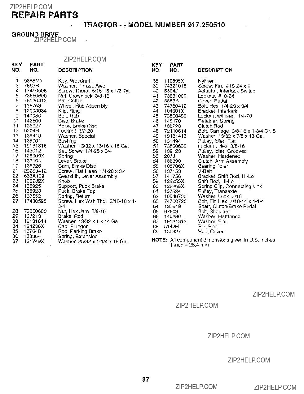
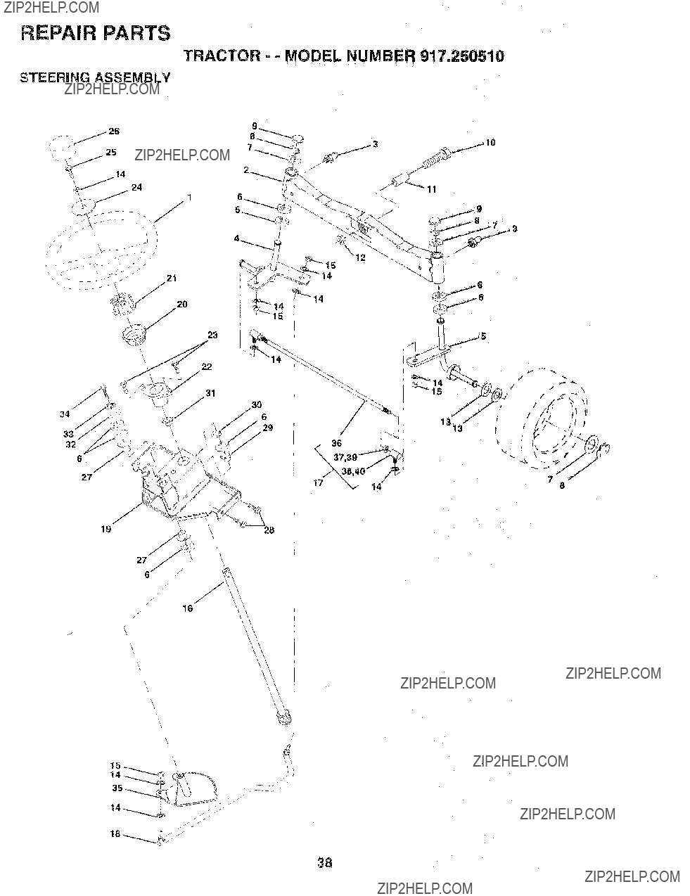
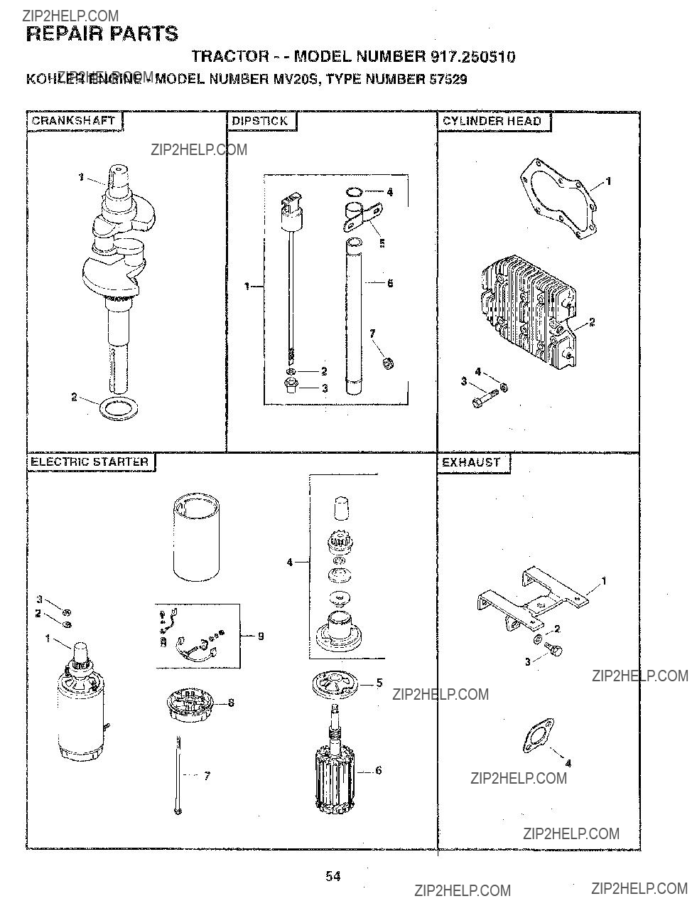
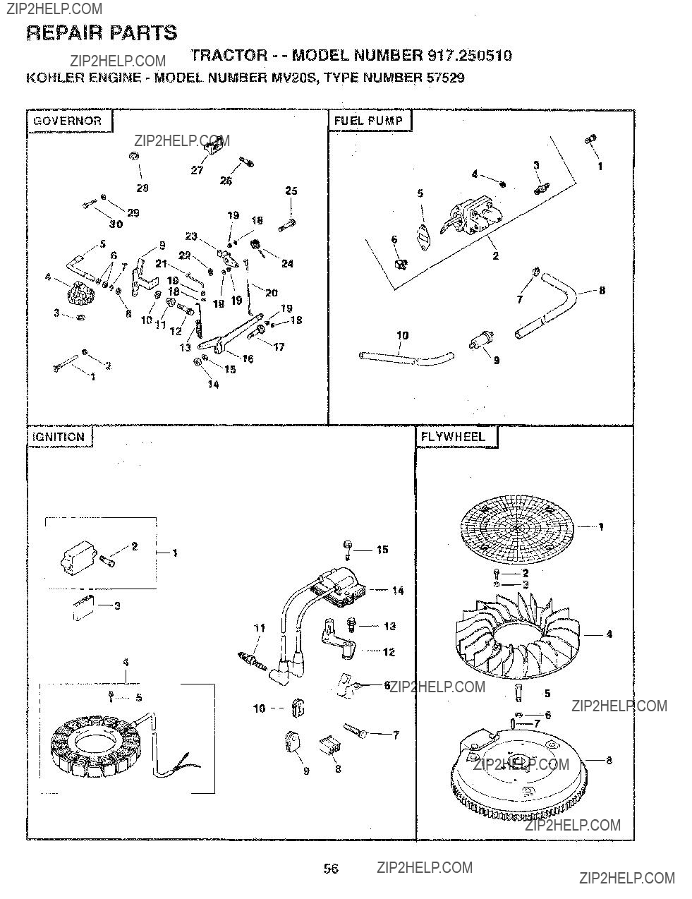
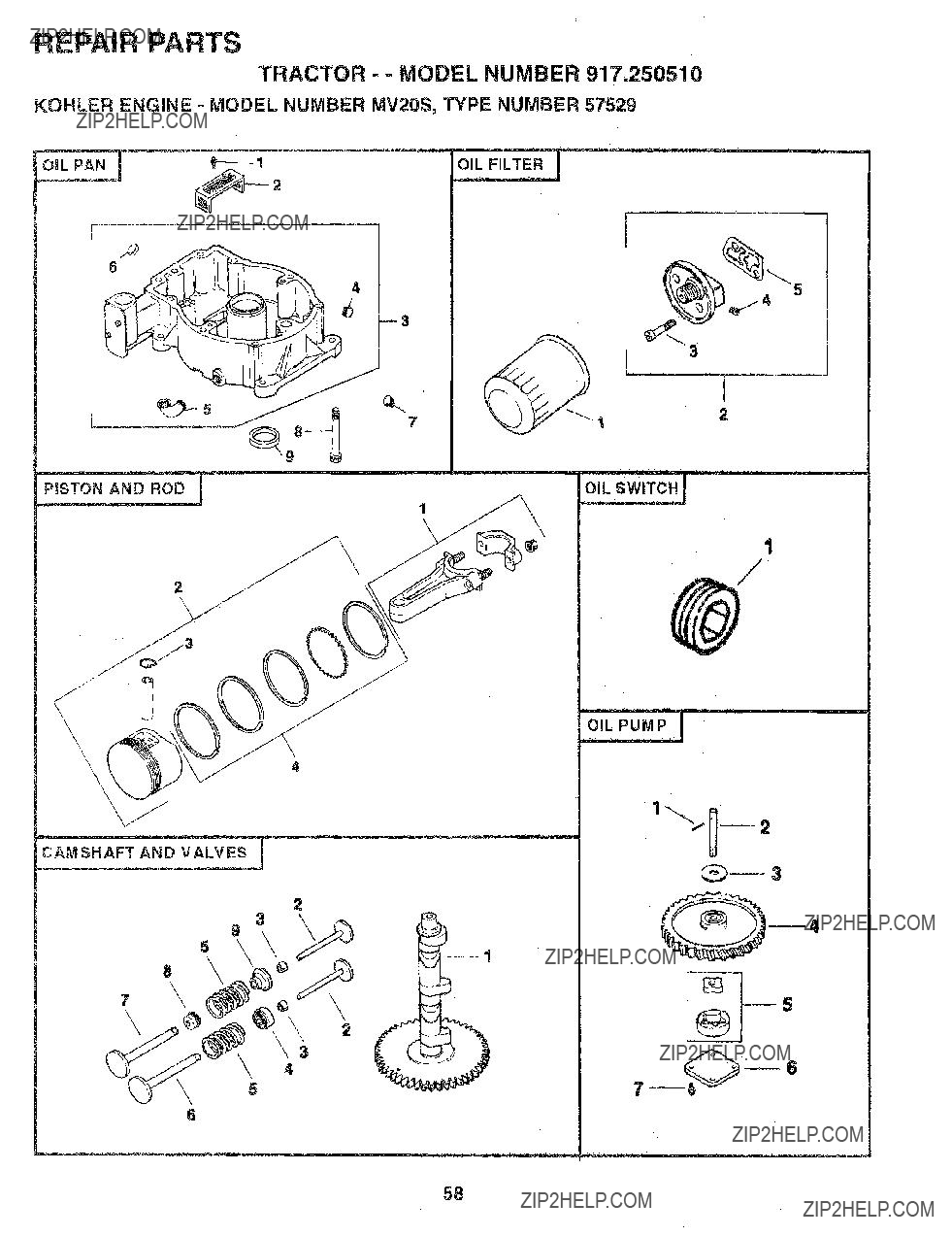
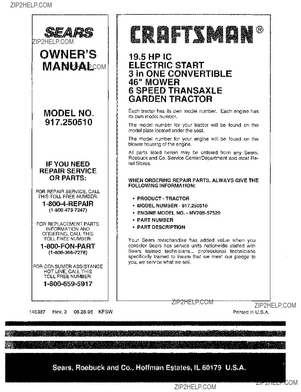
MODEL

NUMBER917.250510

SERIAL

NUMBER

DATEOF PURCHASE

THE MQDELAND SERIAL NUMBERSWILL BE FOUND

ON A PLATE UNDER THE SEAT.

YOU SHOULD RECORD BOTH SERIAL NUMBER AND DATE OF PURCHASE AND KEEP tN A SAFE PLACE

:OR FUTURE REFERENCE.

MAINTENANCE AGREEMENT

A Sears Maintenance Agreement is available on this prod- uct. Contact your nearest Sears store for details.

CUSTOMER RESPONSIBIMTIES

Read and observe the safety rules.

Fottow a regularschedule in maintaining, caring for and using your tractor.

- Follow the instructions under "Customer Responsibili- ties" and "Storage" sections of this owner's manual.

PRODUCT SPECIFICATIONS

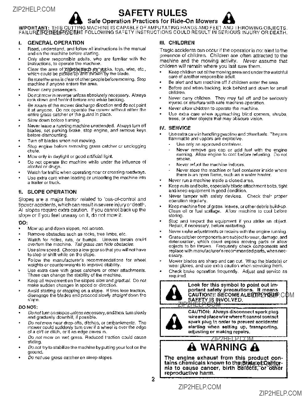
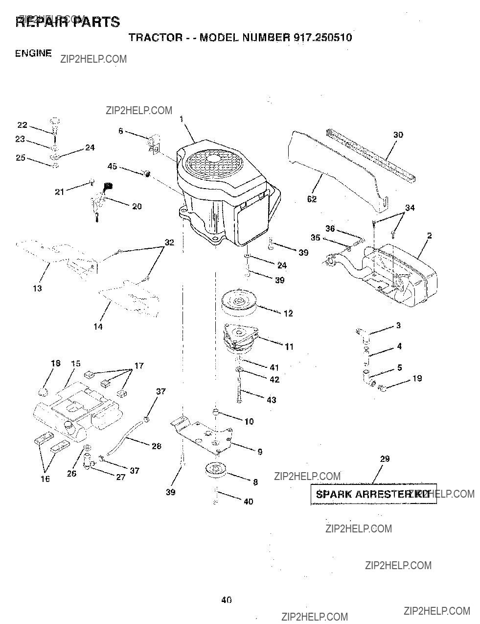
WARNING: This tractor is equipped with an internal combustion engine and should not be used on or near any unimproved forest-covered, brush-covered or grass-cov- ered land unless the engine's exhaust system is equipped with a spark arrester meeting applicable local or state laws (if any). If a spark arrester is used, it should be maintained in effective working order by the operator.

In the state of California the above is required by law (Section 4442 of the California Public Resources Code). Other states may have similar laws. Federal laws apply on federal lands. A spark arrester for the muffler is available through your nearest Sears Authorized Service Center/ Department (See REPAIR PARTS section of this manual).

LIMITED TWO YEAR WARRANTY ON CRAFTSMAN RIDING EQUIPMENT

For two (2) years from the date of purchase, if this Craftsman Riding Equipment is maintained, lubricated and tuned up according to the instructions in the owner's manual, Sears will repair or replace, free of charge, any parts found to be defective in material or workmanship.

This Warranty does not cover:

,,Expendable items which become worn during normal use, such as blades, spark plugs, air cleaners, belts, etc.

,,Tire replacement or repair caused by punctures from outside objects, such as nails, thorns, stumps, or g!ass.

,,Repairs necessary because of operator abuse, negligence, improper storage or accident or the failure to maintain the

equipment according to the instructions contained in the owner's manual.

-Riding equipmen[ used for commercial or rental purposes.

LIMITED 90 DAY WARRANTY ON BATTERY

For ninety (90) days from date of purchase, if any batter,! included with this riding equipment proves defective in material or workmanship and our testing determines the battery wilt not hold a charge, Sears will replace the battery at no charge.

IN-HOME WARRANTY SERVICE ON YOUR CRAFTSMAN RIDING EQUIPMENT IS AVAILABLE AT NO-CHARGE FOR 30

DAYS FROM THE DATE OF PURCHASE. PLEASE CONTACT YOUR NEAREST SERVICE CENTER. AFTER 30 DAYS FROM

THE DATE OF PURCHASE, WARRANTY SERVICE IS AVAILABLE BY TAKING YOUR CRAFTSMAN RIDING EQUIPMENT TO

YOUR NEAREST SEARS SERVICE CENTER. (IN-HOME WARRANTY SERVICE WILL STILL BE AVAILABLE AFTER 30 DAYS

FROM THE DATE OF PURCHASE BUT A STANDARD TRIP CHARGE WILL APPLY.) THIS WARRANTY APPLIES ONLY

WHILE THIS PRODUCT IS IN THE UNITED STATES.

This Warranty gives you specific legal rights, and you may also have other rights which may vary from state to stale.

SEARS, ROEBUCK AND CO., D/817 WA, HOFFMAN ESTATES, IL 60179

3

4

ACCESSORI AND ATTACH ENTS

These accessories and attachments were available through most Sears retail outlets and sen/ice centers when the tractor was purchased. Most Sears stores can order these items for you when you provide the model number of your tractor.

2

PERFORMANCE

Sears offers a wide variety of attachments that fit your tractor. Many of these are listed below with brief explanations of how they can help you. This list was current at the time of publication; however, it may change in future years - more attachments may be added, changes may be made in these attachments, or some may no longer be available or fit your model. Contact your nearest Sears store for the accessories and attachments that are available for your tractor.

Most of these attachments do not require additional hitches or conversion kits (those that do are indicated) and are designed for easy attaching and detaching,

AERATOR promotes deep root growth for a healthy lawn. Tapered 2.5-inch steel spikes mounted on 10-inch diameter discs puncture hoIes in soiI at close intervals to let moisture soak in, Steel weighttray for increased penetration.

BUMPER protects front end of tractor from damage,

CARTS make hauling easy. Variety of sizes available, plus accesso- ries such as side panel kits, too! caddy, cart cover, protective mat and dolly.

CORING AERATOR takes sina!! plugs out of soil to allow moisture and nutrients to reach grass roots, 36-inch swath. 24 hardened steel coring tipsl 150 lb. capacity weight tray.

DiSC HARROW has 2 gangs of 4 steel blades that angle from 10 to 20 degrees. 40 inches wide. Can hook2 units in tandem. (Requires sleeve hitch.)

DOZER BLADE removes snow; grades dirt, sand and gravel. 48 inches wide. !7 inches high, clears 44-inch path when angled, Master lift control lever for operator ease. Spring trip for snow removal on uneven pavement; built-in float for blade to folew ground contour Reversible, replaceable scraper bar, (Use with tire chains and wheel weights and/or rear drawbar weight.)

EASY oIL DRAIN VALVE makes oil changes easier, faster. FRONT NOSE ROLLER canters in front of mower deck to reduce chances of "scalping" on uneven terrain.

GANG HITCH lets you tow 2 or 3 pull-behind attachments at once, such as sweepers, dethatchers, aerators (not for use with rollers, carts or other heavy attachments).

MULCH RAKE/DETHATCHER loosens soil and flips thatch and matted leaves to lawn surface for easy pickup. Twenty spring tine teeth. Useful to prepare bare areas for seeding. Available for front or rear mounting, HIGH PERFORMANCE REEL-ACTION SPRING

"FINE DETHATCHER covers 36qnch wide path and tosses thatch into large hopper, Mounts behind tractor.

PLOW turns soil 6 inches deep. cuts tO-inch furrow. Crank adjust- ment controls depth, 3-position yoke sets width, Heavy steel iandside for straight furrowing. (Requires sleeve hitch.)

RAMP TOPS AND FEET let you load and unload tractor from a pickup truck Use with 2 x 8 or 2 x 10 lumber.

REAR GRADER BLADEis 42 inches wide and operated from driver's seat. Reversible steel btade can be angled at 30 degrees for grading. Reverses for pushing snow backwards. (Requires sleeve hitch.) ROLLER for smoethe r lawn surface. 36-inch wide, 18-inch diameter water4ight drum holds up to 390 Ibs. of weight, Rounded edges prevent harm to turf, Adjustable scraper automatically cleans drum.

SLEEVE CULTIVATOR is 43 inches wide. Prepares ground for seeding, helps weed control. Steel frame holds 5 adjustable sweeps. Adjusts vertically, horizontally. (Requires sleeve hitch,) Optional

accessory: steel furrow opener for wider openings for potatoes, corn, and other deep-seeded crops.

SLEEVE HITCH for use with master tilt system. Single pin coupies/ uncouples.

SNOWTHROWER has 42-inch swath. Drum4ype auger handtes powdery and wet/heavy snow. Mounts easily with simple pin arrange- ment. Discharge chute adjusts from tractor seat, 6-inch diameter spout discharges snow 10 to 50 feet. Lift controlled at tractor seat. (Use with chains and wheel weights and/or rear drawbar weight.)

SPRAYERS use 12-volt DC electric motor that connects to the tractor battery or other 12-volt source. Includes booms for automatic spraying and hand held wand for spot spraying. Wand has adjustable spray pattern. For applying herbicides, insecticides, fungicides and liquid fertilizers.

SPREADER/SEEDERS make seeding, fertilizing, and weed killing

easy, Broadcast spreaders are also useful for granular de-icers and sand.

SWEEPERS let you collect grass c ippings and leaves.

TILLER has 8 hp engine to prepare seed beds, cu tivate, and compost garden residue. Chain-drive transmission. Six ! 1-inch diameter one piece heat treated steel tines. Tills 30-inch bath. (Requires sleeve hitch.) Or use 5 hp tow-behind TBLLER with 36-inch swath to prepare seed beds, cultivate and compost garden residue. Tiller has its own built-in lift and depth controT system and does NOT require a sleeve hitch. Fits any lawn, yard or garden tractor. Simply hook up to the tractor drawbar and go! Optional accessories for 5 hp tiller convert unit for dethatching, aerating, hilling...without tools.

TRRE CHAINS are heavy duty; closely spaced extra-large cross Finks give smooth ride, outstanding traction.

TRACTOR CAB has heavy duty vinyl fabric over tubular steel frame, ABS plastic top; c_ear plastic windshield offers 360 degree visibility. Hinged metal doors with catch. Keeps operator warm and dry. Remove vinyl sidee and winrJshields for use as sun protector in summer, Optional accessories include: tinted/tempered solid safety glass windshield with hand operated wiper; t2wo/t amber caution light for mounting on cab top.

VACS for powerful collection of heavy grass clippings and leaves, Optional wand attachment to pick up debrisin hard to-reach places. VAC/CHIPPER includes a chipper-shredder.

WEIGHT BRACKET for drawbar for snow removal applications. Can be mounted on front of tractor for plowing applications. Uses (1) 55 Ib. weight.

WHEEL WEIGHTS for rear wheels provide needed traction for snow remove! or dozing heavy materials.

(1) Shoulder

Bolt 5/16-18

(1) Washer 17/32 x 1-3/16 x 12 Gauge

(double ioop)

(4) Retainer Springs (single loop)

(2)Weld Nuts #10

(2)Washers 3/16 x 3/4 x 16 Gauge

(2)Hex Bolts 1/4-20 x 3/4

(2)Hex Nuts 1/4-20

(2)Washers 9/32 x

Mulcher

Plate

Steering

Wheel

Parts Bag

Parts bag contents not shown ful! size

_[_(2) Front Link Assemblies _ Q

//",\ Steering

(2) Keys

Steering

Sleeve

Assemblies

Slope Shee t....

6

LY

Your new tractor has been assembled at the factory with exception of those parts left unassembled for shipping purposes. To ensure safe and proper operation of your tractor all parts and hardware you assemble must be tightened securely. Use the correct tools as necessary to insure proper tightness.

TOOLS REQUIRED FOR ASSEMBLY

A socket wrench set will make assembly easier. Standard wrench sizes are listed.

When right or left hand is mentioned in this manual, it means when you are in the operating position (seated behind the steering wheeI).

STEERING

WHEEL

TO REMOVE TRACTOR FROM CARTON

UNPACK CARTON

*Remove all accessible loose parts and parts cartons from carton (See page 6).

-Cut, from top to bottom, along lines on all four corners of carton, and lay panels flat.

-Remove mower and packing materials.

,Check for any additional loose parts or cartons and remove.

STEERING

WHEEL

ADAPTER

STEERING

SLEEVE

BEFORE ROLUNG TRACTOR OFF SKiD

ATTACH STEERING WHEEL (See Fig, 1)

-Remove hex bolt, lock washer and large flat washer from steering shaft.

=Position front wheels of the tractor so they are pointing straight forward.

-Slide steering sleeve over steering shaft.

???Position steering wheel so cross bars are horizontal (left to right) and slide onto steering wheel adapter.

,Secure steering wheei to steering shaft with hex bolt, Iockwasher and large flat washer previously removed, Tighten securely.

???Snap steering wheel insert into center of steering wheel.

-Remove protective plastic from tractor hood and grill.

IMPORTANT: CHECK FOR AND REMOVE ANY STAPLES

IN SKID THAT MAY PUNCTURE TIRES WHERE TRACTOR

IS TO ROLL OFF SKID.

FIG. 1

TO ROLL TRACTOR OFF SKID (See Fig= 6)

???Raise attachment lift lever to its highest position.

oRelease parking brake by depressing clutch/brake pedal.

- Place gearshift lever in neutral (N) position.

???Roll tractor backwards off skid.

ASSEMBLY

CONNECT BATTERY (See Fig. 2)

&CAUTION: Do not short battery termi- nals. Before connecting battery, re- move metal bracelets, wristwatch bands, rings, etc.

Positive terminal must be connected first to prevent sparking from acciden-

tal grounding.

fi

!Lift hood to raised position.

QOpen terminal access doors, remove terminal protec- tive caps and discard.

???If this battery is put into service after month and year indicated on label (label located between terminals) charge battery for minimum of one hour at 6-10 amps.

???First connect RED battery cable to positive (+) battery terminal with hex bolt, fiat washer, lock washer and hex nut as shown. Tighten securely.

???Connect BLACK grounding cable to negative (-) battery terminal with remaining hex bolt, flat washer, lock washer and hex nut. Tighten securely.

???Close terminal access doors.

Use terminal access doors for:

???: Inspection for secure connections (to tighten hard- ware),

???InspeCtion for corrosion.

???Testing battery,

???Jumping (if required).

???Periodic charging.

(RED)

CABLE

NEGATIVE

(BLACK)

CABLE

VENT HOLE

(KEEP CLEAN)

FIG. 2

INSTALL SEAT (See Fig. 3)

Adjust seat before tightening adjustment knob.

*Remove cardboard packing on seat pan.

o Place seat on seat pan and assemble shoulder b01t.

???Assemble adjustment knob and flat washer loosely. Do not tighten.

???Tighten shoulder bolt securely,

???Lower seat into operating position and sit on seat.

oSlide seat until a comfortable position is reached which al!ows you to press clutch/brake pedal a!_ the way down,

o Get off seat without moving its adjusted position.

???Raise seat and tighten adjustment knob securely.

SEAT

SEAT PANX

FIG. 3

CHECK TIRE PRESSURE

The tires on your tractor were overinflated at the factory for shipping purposes. Correct tire pressure is important for" best cutting performance.

???Reduce tire pressure to PSi shown in "PRODUCT SPECIFICATIONS" on page 3 of this manual.

CHECK BRAKE SYSTEM

After you learn how to operate your tractor, check to see that the brake is properly adjusted, See "TO ADJUST BRAKE" in the Service and Adjustments section of this manual.

8

ASSEMBLY

INSTALL MOWER AND DRIVE BELT (See

Figs. 4 and 7)

Be sure tractor is on leve+ surface and mower suspension arms are raised with attachment lift control. Engage park- +rigbrake.

+Cut and remove tie down securing anti-sway bar. Swing anti-sway bar to left side of mower deck.

+Slide mower under tractor with discharge guard to right side of tractor.

IMPORTANT: CHECK BELT FOR PROPER ROUTING IN

ALL MOWER PULLEY GROOVES. INSTALL BELT INTO

ELECTRIC CLUTCH PULLEY GROOVE.

+install One front link in top hole of the R.H. front mower bracket and R.H. front suspension bracket. Retainwith two single loop retainer springs as shown.

+Install second front link in L.H. front suspension bracket

only and retain with single loop retainer spring as shown.

. Turn height adjustment knob counterclockwise until it stops.

+Lower mower linkage with attachment lift control.

+Place the L.H. suspension arm on inward pointing deck

pin. tf necessary,, rock and raise front of mower to align deck pin with the hote in suspension arm.

???Slide left side of mower deck back and install the

unattached front link in top hole of the L+H+front mower bracket. Retain with singte loop retainer spring as shown.

+Place the R.H. suspension arm on inward pointing deck pin. If necessary, rock and raise front of mower to align deck pin with the hole in suspension arm.

+Connect anti-sway bar to chassis bracket under left footrest and retain with double loop retainer spring.

+Retain both suspension arms to deck pins with double loop retainer springs.

+Turn height adjustment knob clockwise to remove slack from mower suspension.

+Raise deck to highest position.

+Assemble gauge wheels (See "TO ADJUST GAUGE WHEELS" in the Operation section of this manual).

CHECK DECK LEVELNESS

For best cutting results, mower housing should be properly leveled. See '%0 LEVEL MOWER HOUSING" in the

Service and Adjustments section of this manual.

CHECK FOR PROPER POSITION OF ALL

BELTS

See the figures that are shown for replacing motion, mower drive, and mower blade drive belts in the Service and Adjustments section of this manual. Verify that the belts are routed correctly.

FiG. 4

ASSEMBLY

'ii

INSTALL MULCHER PLATE

(See Figs. 5A and 5B)

-tnStall two latch hooks to mulcher plate using screw, washer, lock washer, and weld nut as shown.

NOTE: Pre-assemble weld nut to latch hook by inserting weld nut from the top with hook pointing down.

???Tighten hardware securely.

??Raise and hold deflector shield in upright position,

???Place front of mulcher plate over front of mower deck opening and slide into place, as shown.

???Hook front latch into hole on front of mower deck.

,,Hook rear latch into hole on back of mower deck.

guard from mower. Raise and hold guard when attaching mulcher plate

and allow it to rest on plate while in i & CAUTION: Do not remove discharge

operation,

TO CONVERT TO BAGGING OR

DISCHARGING

Simply remove mulcher plate and store in a safe place. Your mower is now ready for discharging or installation of optional grass catcher accessory.

NOTE: It is not necessary to change blades, The mulcher blades are designed for discharging and bagging also.

i

DEFLECTOR

SHIELD

LATCH

HOOKS

FIG. 5B

,/CHECKLIST

BEFORE YOU OPERATE AND ENJOY YOUR NEW

TRACTOR, WE WISH TO ASSURE THAT YOU RECEIVE

THE BEST PERFORMANCE AND SATISFACTION FROM

THIS QUALITY PRODUCT.

PLEASE REVIEW THE FOLLOWING CHECKLIST:

v" All assembly instructions have been completed.

,/ No remaining loose parts in carton.

,/ Battery is properly prepared and charged. (Minimum 1 hour at 6 amps).

,/ Seat is adjusted comfortably and tightened securely.

,/ All tires are properly inflated. (For shipping purposes, the tires were overinflated at the factory).

,/ Be sure mower deck is properly leveled side-to-side! front-to-rear for best cutting results. (Tires must be properly inflated for leveling).

,/ Check mower and drive belts. Be sure they are routed properly around pulleys and inside all belt keepers.

,/ Check wiring. See that all connections are still secure and wires are properly clamped.

WHILE LEARNING HOW TO USE YOUR TRACTOR, PAY

EXTRA A TTENTION TO THE FOLLOWING IMPORTANT

ITEMS:

,/ Engine oil is at proper level???

??Fuel tank is filled with fresh, clean, regular unleaded gasoline.

,/ Become familiar with all controls - their location and function. ??perate them before you start the engine.

,/ Be sure brake system is in safe operating condition.

10

OPERATION

These symbols may appear on your tractor or in literature supplied with the product. Learn and understand their mea_ing.

11

OPERATION

KNOW YOUR TRACTOR

READ THIS OWNER'S MANUAL AND SAFETY RULES BEFORE OPERATING YOUR TRACTOR

Co mpare the i!lustrations with you rtractor to familiarize you rself with the locations of various controls and adjustments. Save this manual for future reference.

ATTACHMENT CLUTCH SWITCH

AMMETER

CHOKECONTROL

LIGHT SWITCH

LIFT LEVER

CLUTCH/BRAKE

PEDAL

THROTTLE

CONTROL

PARKING BRAKE

LEVER

HEIGHT

RANGE SHIFT

LEVER

ADJUSTMENT

KNOB

GEARSHIFT LEVER

FIG. 6

Our tractors conform to the safety standards of the American National Standards Institute,

ATTACHMENT CLUTCH SWITCH- Used to engage mower blades or other attachments mounted to your tractor.

LIFT LEVER - Used to raise and lower mower deck or other attaChments mounted to your tractor.

LIFT LEVER PLUNGER - Used to release attachement lift lever when changing its position.

CLUTCH/BRAKE PEDAL - Used for declutching and braking the tractor and starting the engine.

GEARSHIFT LEVER = Selects the speed and direction of tractor.

THROTTLE CONTROL - Used to control engine speed.

RANGE SHIFT LEVER - Allows high (H) or low (L) speed for all forward and reverse gears.

IGNITION SWITCH - Used to start and stop the engine.

AMMETER - Indicates battery charging (+) or discharging

(-).

LIGHT SWITCH - Turns the headlights on and off.

PARKING BRAKE LEVER - Locks clutch/brake pedal into the brake position.

CHOKE CONTROL - Used when starting a cold engine.

HEIGHT ADJUSTMENT KNOB- Used to adjust the mower height.

12

OPERATION

The operation of any tractor can result in foreign objects thrown into the eyes, which can

result in severe eye damage. Always wear safety glasses or eye shields while operating your tractor or performing any adjustments or repairs. We recommend a wide vision safety mask over the spectacles or standard safety glasses.

HOW TO USE YOUR TRACTOR

NOTE: Under certain conditions when tractor is standing

TO SET PARKING BRAKE (See Fig. 7)

Your tracto r is equipped with an operator presence sensing switch. When engine is running, any attempt by the operator to leave the seat without first setting the parking brake will shut off the engine.

,Depress clutch/brake pedal into fult "BRAKE" position and hold.

idle with the engine running, hot engine exhaust gases may cause "browning" of grass. To eliminate this possibility, always stop engine when stopping tractor on grass areas.

Place parking brake lever in "ENGAGED" position and release pressure from clutch/brake pedal. Pedal should remain in "BRAKE" position. Make sure parking brake will hold tractor secure.

CHOKE

CONTROL

LEVER

TO USE THROTTLE CONTROL (See Fig. 7)

Always operate engine at full throttle.

Operating engine at less than full throttle reduces the battery charging rate.

??Full throttle offers the best mower performance.

TO USE CHOKE CONTROL (See Fig. 7)

Use choke control whenever you are starting a cotd engine. Do not use to start a warm engine.

???To engage choke control, pult knob out. Slowly push knob in to disengage.

TO MOVE FORWARD AND BACKWARD

(See Fig. 7)

The direction and speed of movement is controlled by the gearshift lever.

-Start tractor with clutch/brake pedal depressed and gearshift lever in neutral (N) position.

oMove gearshift and range shift ievers to desired posi- tion.

o Stowly release clutch!brake pedal to start movement.

IMPORTANT: BRING TRACTOR TO A COMPLETE STOP

BEFORE SHIFTING OR CHANGING GEARS. FAILURE

TO DO SO WILL SHORTEN THE USEFUL LIFE OF YOUR

TRANSAXLE.

FIG. 7

STOPPING (See Fig. 7)

MOWER BLADES -

o Move attachment clutch switch to "DISENGAGED" position.

GROUND DRIVE -

Depress clutch/brake pedal into furl "BRAKE" position.

??? Move gearshift lever to neutral (N) position.

ENGINE -

???Move throttle control to slow (_) position.

NOTE: Failure to move throttle control to slow (,_) position and alIowing engine to idle before stopping may cause engine to "backfire".

=Turn ignition key to "OFF" position and remove key.

Always remove key when leaving tractor to prevent unauthorized use.

TO ADJUST MOWER CUTTING HEIGHT

(See Fig. 7)

The cutting height is controlled by turning the height adjust- ment knob in desired direction.

-Turn knob clockwise (S-_) to raise cutting height.

Turn knob counterclockwise (1_-_) to lower cutting height.

The cutting height range is approximately 1-1/4" to 4-1/4". The heights are measured from the ground to the blade tip with the engine not running. These heights are approxi- mate and may vary depending upon soil conditions, height of grass and types of grass being mowed.

,The average lawn should be cut to approximately 2-1/2 inches during the cool season and to over 3 inches

during hot months. For healthier and better looking lawns, mow often and after moderate growth,

. For best cutting performance, grass over 6 inches in height should be mowed twice. Make the first cut relatively high; the second to desired height.

OP

TO ADJUST GAUGE WHEELS (See Fig. 8)

Adjust gauge wheels with tractor on a fiat level surface.

,Adjust mower to desired cutting height (See "TO AD- JUST MOWER CUTTING HEIGHT" in the Operation section of this manual).

-With mower in desired height of cut position, gauge wheels should be assembled so they are slightly off the ground, install gauge wheel in appropriate hole with shoulder bolt, 3/8 washer, and 3/8-16 Iocknut and tighten securely.

???Repeat for opposite side installing gauge wheel in same adjustment hole.

GUAGE

WHEEL

MOUNTING

BRACKET\\\

TO OPERATE MOWER (See Figs. 6 and 7)

Your tractor is equipped with an operator presence sens- ing switch. Any attempt by the operator to leave the seat with the engine running and the attachment clutch en- gaged will shut off the engine.

???Select desired height of cut.

???Lower mower with attachment lift control.

???Start mower blades by engaging attachment clutch control.

,TO STOP MOWER BLADES - disengage attachment clutch control,

TO TRANSPORT

,Raise attachment lift to highest position with attach- ment lift control.

,When pushing or towing your tractor, be sure gearshift lever is in neutral (N) position.

??? Do not push or tow tractor at more than five (5) MPH. NOTE: To protect hood from damage when transporting your tractor on atruckor a trailer, be sure hood is closed and secured to tractor. Use an appropriate means of tying hood to tractor (rope, cord, etc.).

BEFORE STARTING THE ENGINE

CHECK ENGINE OIL LEVEL (See Fig. 9)

???The engine in your tractor has been shipped, from the factory, already filled with summer weight oil.

???Check engine oi! with tractor on level ground.

,Remove oil fill cap!dipstick and wipe clean, reinsert the dipstick and push it all the way down into the tube, wait for a few seconds, remove and read oil level. If necessary, add oil until "FULL" mark on dipstick is reached. Do not overfill.

,For cold weather operation you should change oil for easier starting (See "OIL VISCOSITY CHART" in the Customer Responsibilities section of this manual).

To change engine oil, see the Customer Responsibili- ties section in this manual.

OIL DRAIN PLUG

GAP/DIPSTICK

FIG. 9

-Move gearshift lever to 1st gear and range shift iever to

OPERATION

TO START ENGINE (See Fig. 7)

When starting engine for the first time or if engine has run out of fuel, it will take extra cranking time to move fuel from the tank to the engine.

???Depress clutch/brake pedal and set parking brake.

-Move throttle control to midway between fast ('_) and slow (,_b) positions.

-Insert key into ignition and turn key ctockwiseto"START" position and release key as soon as engine starts. Do not run starter continuously for more than fifteen

seconds per minute. If engine does not start after several attempts, move throttle controt to fast ('_)

position, wait a few minutes and try again.

???When engine starts, slowly push choke control in. Move throttle control to fast (,_) position.

,Allow engine to warm up for a few minutes before engaging drive or attachments.

NOTE: If at a high altitude (above 3000 feet) or in cold temperatures (below 32??F), the carburetor fuel mixture may need to be adjusted for best engine performance. See "TO ADJUST CARBURETOR" in the Service and Adjust- ments section of this manual.

MOWING TIPS

Tire chains cannot be used when the mower housing is attached to tractor.

,Mower should be properly Peveled for best mowing performance. See "TO LEVEL MOWER HOUSING" in the Service and Adjustments section of this manual.

*The left hand side of mower should be used for trim- ming.

oDrive so that clippings are discharged onto the area that has been cut. Have the cut area to the right of the machine. This will result in a more even distribution of clippings and more uniform cutting.

,When.mowing large areas, start by turning to the right so that clippings wil! discharge away from shrubs, fences, driveways, etc. After one or two rounds, mow in the opposite direction making left hand turns until finished (See Fig. 10).

If grass is extremely tall, it should be mowed twice to reduce load and possible fire hazard from dried clip- pings. Make first cut relatively high; the second to the desired height.

???Do not mow grass when it is wet. Wet grass will plug mower and leave undesirable clumps. Allow grass to dry before mowing.

=Always operate engine at futt throttle when mowing to assure better mowing performance and proper dis- charge of material. Regulate ground speed by select- ing a low enough gear to give the mower cutting performance as well as the quality of cut desired.

When operating attachments, select a ground speed that will suit the terrain and give best performance of the attachment being used.

MULCHING MOWING TIPS

IMPORTANT: FOR BEST PERFORMANCE, KEEP

MOWER HOUSING FREE OF BUILT-UP GRASS AND

TRASH. CLEAN AFTER EACH USE.

The special mulching blade will recut the grass clip- pings many times and reduce them in size so that as they fall onto the lawn they will disperse into the grass and not be noticed. Also, the mulched grass will biodegrade quickly to provide nutrients for the lawn. Always mulch with your highest engine (blade) speed as this will provid_ the best recutting action of the blades.

Avoid cutting your lawn when it is wet. Wet grass tends to form clumps and interferes with the mulching action. The best time to mow your lawn is the early afternoon. At this time the grass has dried and the newly cut area will not be exposed to the direct sun.

,,For best results, adjust the mower cutting height so that the mower cuts off only the top one-third of the grass blades (See Fig. 11). For extremely heavy mulching, reduce you rwidth of cut on each pass and mow slowly.

??Certain types of grass and grass conditions may re- quire that an area be mulched a second time to com- pletely hide the clippings. When doing a second cut, mow across or perpendicular to the first cut path.

Change your cutting pattern from week to week. Mow north to south one week then change to east to west the

next weeko This will heip prevent matting and graining of the lawn.

( "-

FiG. 11

FIG, 10

15

CUSTOMER RESPONSIBILITIES

_Hllrq-i

MAINTENANCE SCHEDULE

F,LL,DATES.

AS YOU COMPLETE

REGULAR:SERVICE

Check Brake Operation

Check Tire Pressure

T Check for Loose Fasteners

If'I_

v'

t,1

C

Sharpen/Replace Mower Blades

Lubrication Chart

v'

T Check Battery Level/Recharge

0 Clean Battery and Terminals

RCheck Transaxle Cooling Adjust Blade Belt(s) Tension

v'

E

N

Adjust Motion Drive Belt(s) Tension

i

Check Engine Oil Level

Change EngineOil

Clean Air Filter

Clean Air Screen

v'51

V' ,23 V'

G Inspect Muffler/Spark Arrester

I Replace Oil Filter (If equipped)

N

v'

I I/_,2

V'2

E

Clean Engine Cooling Fins

Replace Spark Plug

Replace Air Filter Paper Cartridge

GENERAL RECOMMENDATIONS

The warranty on this tractor does not cover items that have been subjected to operator abuse or negligence. To

receive full value from the warranty, operator must maintain tractor as instructed in this manual.

Some adjustments wilt need to be made periodically to properly maintain your tractor.

All adjustments in the Service and Adjustments section of this manual should be checked at least once each season,

Once a year you should replace the spark plug, clean or replace air filter, and check blades and belts for wear_ A new spark plug and clean air filter assure proper air-fuel mixture and help your engine run better and last longer.

BEFORE EACH USE

???Check engine oil level.

o Check brake operation.

??Check tire pressure,

???Check for loose fasteners.

IMPORTANT: DO NOT OIL OR GREASE THE PIVOT

POINTS WHICH HAVE SPECIAL NYLON BEARINGS.

VISCOUS LUBRICANTS WILL ATTRACT DUST AND DiRT

THAT WILL SHORTEN THE LIFE OF THE SELF-

LUBRICATING BEARINGS. IF YOU FEEL THEY MUST

(_)CHE

TRANSAXLE

FLUID

(_)SAE 30 MOTOR OIL API - SF/SG

(_) GENERAL PURPOSE GREASE

(_) REFER TO CUSTOMER RESPONSIBILITIES "ENGINE" SECTION

(_)SPRAY SILICONE LUBRICANT (MOVE BOOTS TO LUBRICATE)

CUSTOME ESPONSIBILITIES

TRACTOR

Always observe safety rules when performing any mainte- nance.

BRAKE OPERATION

If unit requires more than six (6) feet stopping distance at high speed in highest gear, then brake must be adjusted. (See "TO ADJUST BRAKE" in the Service and Adjust- ments section of this manual).

TIRES

???Maintain proper air pressure in all tires (See "PROD- UCT SPECIFICATIONS" on page 3 of this manual).

Keep tires free of gasoline, oil, or insect control chemi- cals which can harm rubber.

Avoid stumps, stones, deep ruts, sharp objects and other hazards that may cause tire damage.

The blade can be sharpened with a file or on a grinding wheel. Do not attempt to sharpen while on the mower.

To check blade balance, you w I1need a 5/8 drameter

steel bolt, pin, or a cone balancer. (When using a cone balancer, follow the instructions supplied with bal- ancer).

Slide bladeon to an unthreaded portion of the steel bolt or pin and hold the bolt or pin parallel with the ground. tf blade is balanced, it should remain in a horizontal position. If either end of the blade moves downward, sharpen the heavy end until the blade is balanced.

NOTE: Do not use a nail for balancing blade. The lobes of the center hole may appear to be centered, but are not.

BLADE CARE

For best results mower blades must be kept sharp. Re- place bent or damaged blades.

BLADE REMOVAL (See Fig. 12)

5!8" BOLT

BLADE

*Raise mower to highest position to allow access to blades.

oRemove hex bolt, lock washer and flat washer securing blade.

,Install new or resharpened blade with trailing edge up towards deck as shown.

Reassemble hex bolt, lock washer and flat washer in exact order as shown.

,Tighten bolt securely (30-35 Ft. Lbs. torque).

!MPORTANT: BLADE BOLT 1SGRADE8HEATTREATED.

NOTE: We do not recommend sharpening blade- but if you do, be sure the blade is balanced.

BLADE

TRAILING

EDGE UP

HEX BOLT (GRADE 8)*_

*A GRADE 8 HEAT TREATED BOLT CAN BE

IDENTIFIED BY SIX LINES ON THE BOLT HEAD,

FiG. 12

FiG. 13

V-BELTS

Check V-belts for deterioration and wear after 100 hours and replace if necessary. The belts are not adjustable. Replace belts if they begin to slip from wear.

TRANSAXLE COOLING

Keep transaxle free from build-up of dirt and chaff which can restrict cooling.

CHECK TRANSAXLE OiL LEVEL

(See Fig. 14)

-Block up rear axle securely.

,Remove left rear wheel by removing hub bolts.

,Remove filler plug from transaxle. Oil level must be even with plug threads. If necessary', fill with SAE 30 motor oil, API-SF or SG. Replace filler plug.

???Reassemble wheel to hub.

???For approximate capacity see "PRODUCT SPECIFI- CATIONS" on page 3 of this manual.

TRANSAXLE

LER PLUG

TO SHARPEN BLADE (See Fig. 13)

17

CUSTOM ESPO ILITIES

BATTERY

Your tractor has a battery charging system which is suffi- cient for normal use. However, periodic charging of the battery with an automotive charger will extend its life.

???Keep battery and terminals clean. = Keep battery bolts tight.

???Keep small vent holes open (See "CONNECT BAT- TERY" in tl,e Assembly section of this manual).

,, Recharge at 6-10 amperes for 1 hour.

TO CLEAN BATTERY AND TERMINALS

Corrosion and dirt on the battery and terminals can cause the battery to "leak" power.

???, Remove terminal guard.

=Disconnect BLACK battery cable first then RED bat- tery cable and remove battery from tractor.

,,Wash battery with solution of four tablespoons of baking soda to one gallon of water. Be careful not to get the soda solution into the ceils.

=Rinse the battery with plain water and dry.

=Clean terminals and battery cable ends with wire brush until bright.

-Coat terminals with grease or petroleum jelly.

,Reinstall battery (See "CONNECT BATTERY" in the Assembly section of this manual).

Change the oil after the first two hours of operation and every 50 hours thereafter or at least once a year if the tractor is not used for 50 hours in one year,

Check the crankcase oil level before starting the engine and after each eight (8) hours of operation. Tighten oil fill cap/dipstick securely each time you check the oil level.

TO CHANGE ENGINE OIL (See Fig. 15)

Determine temperature range expected before oil change, All oi! must meet API service classification SF or SG,

Be sure tractor is on level surface.

, Oil will drain more freely when warm.

???Catch oil in a suitable container.

???Remove oil fil! cap/dipstick. Be careful not to allow dirt to enter the engine when changing ol,

. Remove drain plug.

=After oil has drained completely, replace oil drain plug and tighten securely.

=Refill engine with oil through oil fill dipstick tube. Pour slowly, Do not overfill. For approximate capacity see "PRODUCT SPECIFICATIONS" on page 3 of this manual.

???Use gauge on oil fill cap/dipstick for checking level. Be sure dipstick is in all the way for accurate reading. Keep oil at "FULL" line on dipstick.

OIL DRAIN PLUG

ENGINE

LUBRICATION

Only use high quality detergent oi! rated with API service classification SF or SG. Select the oil'sSAE viscosity grade according to your expected operating temperature.

SAE V SCOSITY GRADES

NOTE: Although multi-viscosity oils (5W30, 10W30 etc.) improve starting in cold weather, these multi-viscosity oils will result in increased oil consumption when used above 32??F. Check your engine oil level more frequently to avoid possible engine damage from running low on oi!.

OIL FILL

CAP/DIPSTICK

FIG. 15

18

CUSTO RESPON BiLITIES

CLEAN AIR SCREEN (See Fig. 16)

Air screen must be kept free of dirt and chaff to prevent engine damage from overheating. Clean with a wire brush or compressed air to remove dirt and stubborn dried gum fibers.

: _,ENGINE COOLING FiNS (See Fig. 16)

Remove any dust, dirt or oil from engine cooling fins to

prevent engine damage from overheating. Engine blower housing must be removed. Remove side panels and hood (See "TO REMOVE HOOD AND GRILL ASSEMBLY" in the

Service and Adjustments section of this manual).FIG. 17

COOLING FINS

(BOTH SIDES)

AIR SCREEN

MUFFLER

Inspect and replace corroded muffler and spark arrester (if equipped) as it could create a fire hazard and/or damage.

SPARK PLUGS

Replace spark plugs at the beginning of each mowing season or after every 100 hours of operation, whichever comes first. Spark ptug type and gap setting are shown in "PRODUCT SPECIFICATIONS" on page 3 of this manual.

\

ENGINE OIL FILTER

FiG. 16

AIR FILTER (See Fig. 17)

Your engine wilt not run properly using a dirty air filter. Clean the foam pre-cleaner element after every 25 hours of operation or every season. Service paper cartridge every 100 hours or every season, whichever occurs first.

Service air cleaner more often under dusty conditions.

*Remove wing nut and cover.

= Remove seal and cartridge plate.

TO SERVICE PRE--CLEANER

-Slide foam pre-cleaner off cartridge.

??Wash it in liquid detergent and water.

,Squeeze it dry in a clean cloth.

Saturate it in engine oil. Wrap it in clean, absorbent cloth and squeeze to remove excess oil.

TQ SERVICE CARTRIDGE

Gently tap the flat side of the paper cartridge to dis- lodge dirt. Do not wash the paper cartridge or use pressurized air, as this will damage the cartridge. Replace a dirty, bent, or damaged cartridge.

-Reinstall the pre-cleaner (cleaned and oiled) over the paper cartridge.

???Reassemble air cleaner, cartridge plate, and seal.

Install the air cleaner cover and wing nut. Tighten wing nut 1/2 turn to 1fullturn after nut contacts cover. Do not overtighten.

Replace the engine oil filter every season or every other oil change if the tractor is used more than 100 hours in one year.

IN=LfNE FUEL FILTER (See Fig. 18)

The fuel filter should be replaced once each season. If fuel filter becomes clogged, obstructing fuel flow to carburetor, replacement is required.

With engine cool, remove filter and plug fuel line sections.

Place new fuel filter in position in fuel line with arrow pointing towards carburetor.

=Be sure there are no fuel line Ieaks and clamps are properly positioned.

*immediately wipe up any spilled gasoline.

CLAMP

FUEL FILTER

FIG. 18

CLEANING

,Clean engine, battery, seat, finish, etc. of all foreign matter,

Keep finished surfaces and wheels free of all gasoline, oil, etc.

=Protect painted surfaces with automotive type wax.

We do not recommend using a garden hose to clean your tractor unless the electrical system, muffler, air filter and carburetor are covered to keep water out. Water in engine

19 can result in a shortened engine life.

with plug.

TO REMOVE MOWER (See Fig. 19)

,, Place attachment clutch in "DISENGAGED" position.

=Turn height adjustment knob to lowest setting. Lower mower to its lowest position.

Remove retainer spring holding anti-swaybar to chas- sis bracket and disengage anti-swaybar from bracket.

-Remove retainer springs from suspension arms at deck and disengage arms from deck.

=Raise attachment lift to its highest position.

???Remove two retainer springs from each front link and remove links.

-Slide mower forward and remove belt from electric clutch pulley.

=Slide mower out from under right side of tractor.

IMPORTANT: IF AN ATTACHMENT OTHER THAN THE

MOWER DECK IS TO BE MOUNTED ON THE TRACTOR,

REMOVE THE FRONT LINKS.

TO INSTALL MOWER

Follow procedure described in "INSTALL MOWER AND DRIVE BELT" in the Assembly section of this manual???

TO LEVEL MOWER HOUSING

Adjust the mower while tractor is parked on level ground or driveway. Make sure tires are properly inflated (See "PRODUCT SPEC tFICATIQNS" on page 3 of this manual). Iftires are over or underinfiated, you will not properly adjust your mower.

SIDE-TO-SIDE ADJUSTMENT (See Figs. 19 and 20)

,Raise mower to its highest position.

???Measure height from bottom of deck curl to ground level at front corners of mower. Distance "A" on both sides of mower should be the same.

???If adjustment is necessary, make adjustment on one side of mower only.

-To raise one side of mower, tighten lift link adjustment nut on that side.

To lower one side of mower, loosen lift link adjustment nut on that side.

NOTE: Each fun turn of adjustment nut will change mower

FRONT

SUSPENSION

BRACKET

RETAINER

RETAINER

SPRING

ANTI-SWAY

\

NGS

BRACKET

BARRETAINER

SPRINGS

FIG. 19

\

2O

SERVICE AND

FRONT-TO-BACK ADJUSTMENT (See Figs. 21 and 22) -

IMPORTANT: DECK MUST BE LEVEL SIDE-TO-SIDE. IF

THE FOLLOWING FRONT-TO-BACK ADJUSTMENT IS

NECESSARY, BE SURE TO ADJUST BOTH FRONT LINKS

EQUALLY SO MOWER WILL STAY LEVEL SIDE-TO-SIDE. To obtain the best cutting results, the mower housing should be adjusted so the front is approximately 1/8" to 1/2" lower than the rear when the mower is in its highest position.

Check adjustment on right side of tractor. Measure dis- tance "F" directly in front of and behind the mandrel at bottom edge of mower housing as shown.

???Before making any necessary adjustments, check that both front links are equal in length.

???If links are not equal in length, adjust one link to same length as other link.

-To lower front of mower housing, loosen nut"G" on both front links an equal number of turns.

???When distance "F" is 1/8" to 1/2" lower at front than

rear, tighten nut"H" against trunnion on both front links.

. To raise front of mower housing, loosen nut "H" from ti'unnion on both front links. Tighten nut "G" on both front links an equal number of turns.

-When distance "F" is 1/8" to 1/2" lower at front than

rear, tighten nut "H" against trunnion on both front links.

NOTE: Each full turn of nut "G" will change dim. "F" by approximately 3/8".

Recheck side-to-side adjustment.

ADJUSTMENTS

TO REPLACE MOWER DRIVE BELT

MOWER DRIVE BELT REMOVAL (See Fig. 23) -

=Park tractor on a level surface. Engage parking brake.

=Remove four screws from LH. mandrel cover and remove cover.

???Roll belt over the top of L.H. mandrel pulley.

-Remove belt from electric clutch pulley.

-Remove belt from idler pulleys.

???Remove any dirt or grass clippings which may have accumulated around mandrels and entire upper deck surface.

Check primary idler arm and two idlers to see that they rotate freely.

"Be sure spring is securely hooked to primary idler arm and bolt in mower housing.

MOWER DRIVE BELT INSTALLATIOI'q (See Fig. 23) -

=Install belt in both idlers. Make su re belt is in both belt keepers at the idlers as shown.

Install new belt onto electric clutch pulley.

Rol! belt into upper groove of L.H. mandrel pulley.

???Carefully check belt routing making sure belt is in the grooves correctly and inside belt keepers.

=Reassemble LH. mandret cover.

L.H.SCREWS

MANDRELIDLER

PULLEYS

_F_

COVER X

ELECTRIC

MOWER_ CLUTCH

DRIVE BELT i _'" _'PULLEY

FIG. 21

.?

BOTH FRONT LINKS SHOULD BE EQUAL IN LENGTH

FIG. 23

NUT "N

FRONT LINKS

TRUNNION

FIG. 22

21

SERVICE AND

TO REPLACE MOWER BLADE DRIVE BELT

(See Fig. 24)

Park the tractor on level surface. Engage parking brake.

,Remove mower drive belt (See "TO REPLACE MOWER DRIVE BELT" in this section of this manual).

,,Remove mower (See "TO REMOVE MOWER" in this

section of this manual).

???Remove four screws from R.H. mandrel cover and remove cover. Unhook spring from bolt on mower housing.

,Carefully roll belt off R.H. mandrel pulley.

-Remove belt from center mandrel pulley, idler pulley, and LH. mandrel pulley.

???Remove any dirt or grass which may have accumu- lated around mandrels and entire upper deck surface.

???Check secondary idler arm and idler to see that they rotate freely.

,,Be sure spring is hooked in secondary idler arm and sway-bar bracket.

,Install new belt in lower groove of LH. mandrel pulley, idler pulley, and center mandrel pulley as shown.

Roll belt over R.H. mandrel pulley. Make sure belt is in

al! grooves properly.

,,Reconnect spring to bolt in mower housing and rein- stall R.H. manorei cover.

-Reinstall mower totractor (See'q-o INSTALL MOWER" in the Assembly section of this manual).

=Reassemble mower drive belt (See "TO REPLACE MOWER DRIVE BELT" in this section of this manual).

L.H,MOWERCENTER

MANDREL BLADEMANDREL

DRIVE BELT

iDLER

RoB,

MANDREL

COVER

IDLER ARM

SPRING

SWAY-BAR " _

BRACKETSCREW

FIG. 24

TO ADJUST ATTACHMENT CLUTCH

(See Fig. 25)

The electric clutch should provide years of service. The clutch has a built-in brake that stops the pulley within 5 seconds. Eventually, the internal brake will wear which may cause the mower blades to not engage, or, to not stop as required. Adjustments should be made by your nearest authorized service center/department.

???Make sure attachment clutch and ignition switches are in "OFF" position.

,Adjust the three nylon locknuts until space between clutch plate and rotor measures .012" at al! three slot locations cut inside of brake plate.

ADJUSTMENTS

NO'rE: After installing a new electric clutch, run tractor at full throttle and engage and disengage electric clutch 10 cycles to wear in clutch plate,

/_ ...................._=_i _ ......................y-!

FIG. 25

TO ADJUST BRAKE (See Fig, 26)

Your tractor is equipped with an adjustable brake system which is mounted on the left side of the transaxle.

If tractor requires more than six (6) feet stopping distance at high speed in highest gear, then brake must be adjusted.

,,Depress clutch/brake pedal and engage parking brake.

=Measure distance between brake operating arm and nut "A" on brake rod.

If distance is other than 1-3/4", loosen am nut and turn nut "A" until distance becomes !-3/4". Retighten jam nut against nut "A".

Road test tractor for proper stoppin g distance as stated above. Readjust if necessary. If stopping distance is still greater than six (6) feet in highest gear, further maintenance is necessary, Contact your nearest au- thorized service center/department.

WITH PARKING BRAKE"ENGAGE"

NUT "A"

OPERATING

ARM

FIG. 26

22

SERVICE AND ADJUSTMENTS

TO REPLACE MOTION DRIVE BELT

(See Fig. 27)

Park the tractor on level surface. Engage parking brake. For ease of service there is a belt installation guide decal on bottom of left footrest. It is not necessary to remove mower.

BELT REMOVAL -

=Engage parking brake (creates slack in belt).

,,Remove mower drive belt from electric clutch pulley only (See "TO REPLACE MOWER DRIVE BELT" in this section of this manual).

Roll motion drive belt off transaxle pulley.

,,Rol! belt off clutching idler pulleys, then off engine puley and front V-idler pulley.

Pul! belt out of at! belt keepers.

BELT INSTALLATION -

???Place V part of belt into grooves on engine pulley and front V-idler, making sure to route belt inside of belt keepers.

???Put belt coming from V-idler above midspan belt keeper, then onto clutching idler pulleys as shown.

-Make sure V part of belt engages V-idler.

???Place belt around transaxle pulley, beginning at top. V part of belt should engage transaxle pulley.

-Place tong lower section of belt through loop in midspan belt keeper.

???Check to be sure belt is on proper side of all belt keepers.

= Reinstall mower drive belt onto electric clutch pulley. iMPORTANT: CHECK BRAKE ADJUSTMENT.

TO ADJUST STEERING .WHEEL ALIGNMENT

If steering wheel crossbars are not horizontal (left to right) when wheels are positioned straight forward, remove steer- ing wheel and reassemble per instructions in the Assembly section of this manual.

FRONT WHEEL TOE-IN ADJUSTMENT

Front wheel toe-in is required for proper steering operation. Toe-in was set at the factory and adjustment should not be necessary. If parts in the front axle or steering mechanism have been replaced or damaged, check toe-in and adjust if necessary.

TO CHECK TOE-IN (See Fig. 28) -

Position front wheels straight ahead.

Measure distance between wheels at front and rear of tires (dimensions "A" and "B").

,Front dimension "A" should be 1/8" to 1/4" Iess than rear dimension "B".

TO ADJUST TOE-IN (See Figs. 28 and 29) -

=Loosen jam nuts at adjustment sleeves on tie rod.

,Adjust tie rod until dimension "A" is t/8" to 1/4" Iess than dimension "B".

Tighten jam nuts securely.

b,--B

/

/

BELT

KEEPEBELT

TWISTS

BELT TRANSAXLE

KEEPER PULLEY

V-|DLER

JAM NUTS

AS VIEWED FROM BOTTOM

FIG. 27

FIG. 29

FRONT WHEEL CAMBER

The front wheel camber is not adjustable on your tractor. If damage has occurred to affect the front wheel camber,

contact your nearest authorized service center/depart- ment.

23

SERVICE ADJUSTMENTS

TO REMOVE WHEEL FOR REPAIRS

FRONT WHEEL (See Fig. 30) -

???Block up axle securely.

???Remove axle cover, retaining ring and washers to allow wheel removal.

,Repair tire and reassemble.

-Replace washers and snap retaining ring securely in axle groove.

???Replace axle cover.

WASHERS

RETAINING

RING_

AXLE \

COVERxj

PA??ELO\/

FIG. 30

REAR WHEEL -

Block rear axle securely.

=Remove five (5) hub bolts to allow wheel removal.

oRepair tire and reassemble. Replace and tighten hub bolts securely.

TO START ENGINE WITH A WEAK BATTERY

(See Figs. 3!)

CAUTION: Lead-acid batteries gener- ateexplosivegases. Keep sparks, flame and smoking materials away from bat- teries. Always wear eye protection when around batteries.

If your battery is too weak to start the engine, it should be recharged. If "jumper cables" are used for emergency starting, follow this procedure:

iMPORTANT: YOUR TRACTOR IS EQUIPPED WITH A I2

VOLT NEGATIVE GROUNDED SYSTEM. THE OTHER

VEHICLE MUST ALSO BE A 12 VOLT NEGATIVE

GROUNDED SYSTEM. DO NOT USE YOUR TRACTOR

BATTERY TO START OTHER VEHICLES.

TO ATTACH JUMPER CABLES -

???Connect each end of the RED cable to the POSITIVE

(+)terminal of each battery, taking care not to short against chassis.

,Connect one end of the BLACK cable to the NEGA- TIVE (-) terminal of fully charged battery.

,Connect the other end of the BLACK cable to a panel bolt on the left side of the tractor, away from fue! tank and battery.

TO REMOVE CABLES, REVERSE ORDER -

'BLACK cable first from chassis and fully charged battery.

???RED cable last from both batteries.

FIG. 31

TO REPLACE HEADLIGHT BULB

,Raise hood.

,Pull bulb holder out of the hole in the backside of the grill.

-Replace bulb in holder and push bulb holder securely back into the hole in the backside of the grill,

Close hood.

INTERLOCKS AND RELAYS

Loose or damaged wiring may cause your tractor to run poorly, stop running, or prevent it from starting.

???Check wiring. See electrical wiring diagram in Repair Parts section of this manual.

TO REPLACE FUSE

Replace with 30 amp automotive-type plug-in fuse. The fuse holder is located behind the dash.

24

SERVICE AN

TO ADJUST ATTACHMENT LiFT SPRING

(See Fig. 32)

,,While holding spring bushing with wrench, loosen jam nut.

Turn adjustment bot clockwise to extend spring and reduce lift effort (for heavier attachments).

,,Turn adjustment bolt counterclockwise for lighter at- tachments.

???Retighten jam nut against spring bushing.

IMPORTANT: DO NOT ADJUST FOR MAXIMUM SPRING

TENSION WHEN USING LIGHT ATTACHMENTS SUCH ASAMOWER. ADJUST LIFT LEVER SPRING TO AIDtN

LIFTING ATTACHMENT. DO NOT OVERPOWER SPR! NG.

WHEN REMOVING ATTACHMENT, ALWAYS ADJUST

SPRING TENSION TO ITS LOWEST POSITION,

ADJUSTMENTS

TO REMOVE HOOD AND GRILL ASSEMBLY

(See Fig. 33)

???Raise hood.

=Unsnap headlight wire connector.

???Stand in front oftractor. Grasp hoodat sides, tilt toward engine and lift off of tractor.

???To replace, reverse above procedure.

HOOD

\

?? ATTACHMENT

JAM NUT LIFT SPRING

FIG, 32

FIG. 33

25

RViCE ADJUSTMENTS

ENGINE

TO ADJUST THROTTLE CONTROL CABLE

(See Figs. 34 and 35)

The throttle control has been preset at the factory and adjustment should not be necessary, Check adjustment as described below before loosening cable. If adjustment is necessary, proceed as follows:

=With engine not running, move throttle control lever to fast (,f_) position.

,Check that speed control lever is against stop screw. If it is not, loosen casing clamp screw and pull throttle cable until lever is against screw. Tighten clamp screw securely.

TO ADJUST CARBURETOR (See Fig= 36)

The carburetor has been preset at the factory and adjust- ment should not be necessary, However, minor adjustment may be required to compensate for differences in fuel, temperature, altitude or load. If the carburetor does need adjustment, proceed as follows:

In general, turning the adjusting needles in (clockwise) decreases the supply of fuel to the engine giving a leaner fuel/air mixture. Turning the adjusting needles out (coun- terclockwise) increases the supply of fuel to the engine giving a richer fuel/air mixture.

IMPORTANT: DAMAGE TO THE NEEDLES AND THE

SEATS IN CARBURETOR MAY RESULT IF SCREW IS

TURNED IN TOO TIGHT.

PRELIMINARY SETTING -

???Be sure you have a clean air filter, and the throttle control cable is adjusted properly (see above).

???With engine off turn idle fuel adjusting needle in (clock- wise) closing it finger tight and then turn out (counter- clockwise) 1-1/4 turns.

=Turn main fuel adjusting needle in (clockwise) closing finger tight and thentum out (counterclockwise) 1 turn.

FINAL SETTING -

,,Start engine and allow to warm for five minutes, Make

final adjustments with engine running and shift/motion control lever in neutral (N) position.

,,Ide fuel needle setting - With throttle control lever in slow (._b) position, turn idle fuel adjusting needle in (clockwise) until engine begins to die and then turn out (counterclockwise) until engine runs rough. Turn needle to a point midway between those two positions.

???Recheck idle speed, Readjust if necessary.

ACCELERATION TEST

???Move throttle control lever from stow (,_) to fast (,_) position, tf engine hesitates or dies, turn idle mixture screw out (counterclockwise) 1/8 turn. Repeat test and

continue to adjust, if necessary, until engine acceler- ates smoothly.

High speed stop is factory adjusted. Do not adjust-damage may result.

IMPORTANT: NEVER TAMPER WITH THE ENGINE

GOVERNOR, WHICH IS FACTORY SET FOR PROPER

ENGINESPEED. OVERSPEEDINGTHEENGINEABOVE

THE FACTORY HIGH SPEED SETTING CAN BE DANGEROUS. IF YOU THtNKTHE ENGINE-GOVERNED

HIGH SPEED NEEDS ADJUSTING, CONTACT YOUR

NEAREST AUTHORIZED SERVICE CENTER/

DEPARTMENT, WHICH HAS PROPER EQUIPMENT AND

EXPERIENCE TO MAKE ANY NECESSARY

ADJUSTMENTS.

THROTTLE

CONTROL

CABLE

FiG. 34

STOP

SCREW

SPEED

CONTROL

LEVER

FIG. 35

UEL

ADJUSTING

NEEDLE

FiG. 36

26

SERV!CE NOTES

immediately prepare your tractor for storage at the end of the season or if the tractor will not be used for 30 days or more.

gasoline in the tank inside a building

where fumes may reach an open flame CAUTION: Never store the tractor with

or spark. A!low the engine to cool

before storing in any enclosure.

TRACTOR

Remove mower from tractor for winter storage. When mower is to be stored for a period of time, clean it thor- ougfily, remove all dirt, grease, leaves, etc. Store in a clean, dry area.

=Clean entire tractor (See "CLEANING" in the Customer Responsibilities section of this manual).

Inspect and replace belts, if necessary (See belt re- placement instructions in the Service and Adjustments section of this manual).

Lubricate as shown in the Customer Responsibilities section of this manual.

-Be sure that all nuts, bolts and screws are securely fastened. Inspect moving parts for damage, breakage and wear. Replace if necessary.

=Touch up all rusted or chipped paint surfaces; sand lightly before painting.

BATTERY

??Fully charge the battery for storage.

. After a period of time in storage, battery may require recharging.

,To help prevent corrosion and power leakage during long periods of storage, battery cables should be

disconnected and battery cleaned thoroughly (see "TO CLEAN BATTERY AND TERMINALS" in the Cus- tomer Responsibilities section of this manual).

-After cleaning, leave cables disconnected and place cableswhere they cannot come in contact with battery terminals.

???Be sure battery drain tube is securely attached.

???If battery is removed from tractor for storage, do not store battery directly on concrete or damp surfaces.

ENGINE

FUEL SYSTEM

IMPORTANT: IT IS IMPORTANT TO PREVENT GUM DEPOSITS FROM FORMING iN ESSENTIAL FUEL

SYSTEM PARTS SUCH AS CARBURETOR, FUEL FILTER,

FUEL HOSE, OR TANK DURING STORAGE. ALSO, EXPERIENCE INDrCATES THAT ALCOHOL BLENDED

FUELS (CALLED GASOHOL OR USING ETHANOL OR

METHANOL) CAN ATTRACT MOISTURE WHICH LEADS

TO SEPARATION AND FORMATION OF ACIDS DURING

STORAGE. ACIDIC GAS CAN DAMAGE THE FUEL

SYSTEM OF AN ENGINE WHILE IN STORAGE.

Drain the fuel tank.

Start the engine and let it run until the fuel lines and carburetor are empty.

,Never use engine or carburetor cleaner products in the fue! tank or permanent damage may occur.

Use fresh fuel next season.

NOTE: Fue! stabilizer is an acceptable alternative in minimizing the formation of fuel gum deposits during stor- age. Add stabilizer to gasoline in fuel tank or storage container. Always follow the mix ratio found on stabilizer

container. Run engine at least 10 minutes after adding stabilizer to allow the stabilizer to reach the carburetor. Do

not drain the gas tank and carburetor if using fuel stabilizer.

ENGINE OIL

Drain oil (with engine warm) and replace with clean engine oil. (See "ENGINE" in the Customer Responsibilities section of this manual).

CYUNDERS

???Remove spark plug(s).

,Pour one ounce of oil through spark plug hole(s) into cylinder(s).

=Turn ignition key to"START" position for a few seconds to distribute oil.

,Replace with new spark plug(s).

OTHER

Do not store gasoline from one season to another.

???Replace your gasoline can if your can starts to rust. Rust and/or dirt in your gasoline wil! cause problems.

,If possible, store your tractor indoors and cover it to give protection from dust and dirt.

Cover your tractor with a suitable protective cover that does not retain moisture. Do not use plastic. Plastic cannot breathe which allows condensation to form and will cause your tractor to rust.

IMPORTANT: NEVER COVER TRACTOR WHILE ENGINE

AND EXHAUST AREAS ARE STILL WARM.

27

TRO LESHOOTING NTS

Will not start

Hard to start

Engine wilt not turn over

Engine clicks but will not start

Loss of power

ExceSsive vibration

28

29

TRACTOR = MODEL NUMBER 917.250510

SCHEMATIC

/-77

]

30

STORAGE

31

REPAIR PARTS

TRACTOR - - MODEL NUMBER 917.250510

ELECTRICAL

22

24\

42

I

\

1

20

32

31

I

45

\

\

\

\f

/

32

REPAIR PARTS

TRACTOR = -MODEL NUMBER 917.250510

ELECTRICAL

5371031008 Screw Hex Washer Hd #10-32 x 1/2

5473951000 Nut Keps #10-32

NOTE: All component dimensions given in U.S. inches 1 inch = 25.4 mm

33

REPAIR PARTS

TRACTOR - - MODEL NUMBER 917,250510

CHASSIS AND ENCLOSURES

10

1815

38

13

92

848

47120

47

68

22

52

69

28

\

42

56

91

36

20

19

2

24

/

85

34

REPAIR PARTS

TRACTOR == MODEL NUMBER 917.250510

CHASSIS AND ENCLOSURES

KEY PART

NO. NO.

1 144737

2140506

3136671X459

473800700

5145203

6145053

717720408

8145166

9108067X

1019092016

11137270

12137269

13 137271

14136673X459

15136374

16121794X

1717490612

18136373X428

1919131312

2074760616

2173680600

22136670X459

24 145243X459

26 17490512

DESCRIPTION

Rail, Frame RH Drawbar, Gt

Panel Asm., Side LH Nut, Lock Hex 7/16 Unc Dash, Plastic Black Dash Asm., Lower

Screw, Thd Cut 1/4-20 x 1/2 Support, Dash 1-Pc. Battery Nut, Pal

Washer 9/32 x 1-1/4 x 16 Ga. Rivet, Ratchet Male

Washer, Nylon

Rivet, Ratchet Female Hood Asm., Pnt

Lens, Bar Clear

Cover, Access

Screw, Thdrol 3/8-16 x3/4 Grille

Washer 13/32 x 13/16 x 12 Ga. Bolt, Fin Hex 3/8-16 x 1

Nut, Crownlock 3/8-16 Unc Panel Asm., Side RH Footrest, RH

Screw, Thdrol 5/16-18 x 3/4 Footrest, LH

Bracket, Support Dash Saddle, 6sp AYP 1995

Bracket, Support 1-Pc Steering VGT Bracket Asm., Frame Pivot Lh Bracket Asm., Frame Pivot Rh

Bracket, Engine Support Rear Washer 11!32x11!16x16Ga. Bolt, Fin Hex 5/16-18x 3/4 Fender, Pnt.

KEY PART

NO. NO.

4117580408

4272140608

43136939

44136940

45138460

4717490608

48136814

49136813

50136575

5273680500

53 137304

56138461

5773640400

58137113

5974180412

6017490620

6319131614

64144283

67140737

6817490508

69140022

70137159

77137308

84142992

85120404X

8674760716

9011050600

91144735

92143485X013

94100207K

95105531X

106 138776

120 19131616

--8022J

DESCRIPTION

Screw Tap Tite 1/4-20 x 1/2

Bolt, Carriage 3/8-16 x 1

Bracket, Spnsn Front Lh

Bracket, Spnsn Front Rh

Bracket Asm, Susp Chassis Rh

Screw ThdroI 3/8-16 x 1/2

Bracket Asm., Pivot Hood Lh

Bracket Asm, Pivot Hood Rh

Bracket, Chassis Front

Nut, Crownlock 5/16-18

Rod, Support Hood

Bracket Asm., Susp Chassis Lh

Nut, Keps Hex 1/4-20

Bracket Asm., Fender

Screw, Mach Cr 1/4-20 x 3/4

Screw Thdrol 3/8-16 x 1-1/4

Washer 13/32 x 1 x 14 Ga.

Washer, Serrated Disc 13/32 x 1

Guide, Belt T/A

Screw, Thd 5/16-18 x 1/2

Shield, Heat

Guide, Belt Mid Span

Shield, Front

Stop, Over Center Mower

Bracket, Support Transaxle

Boll, Fin Hex 7/16-14 Unc x 1

Washer, Lock External Tooth 3/8

Rail, Frame Lh

Plate, Silkscreen Dash

Clip, Fuel Line

Push Nut, Nylon

Screw, Thdrol Hex Head Zinc Mwr

Washer 13/32 x 1 x 16 Ga.

Plug, Hole

Washer 9/32 x 3/4 x 16 Ga.

Bracket, Axle Front

Bracket, Support Axle/Engine

NOTE: All component dimensions given in U.S. inches 1 inch = 25.4 mm

35

,_OUt_DD_\_

I

9

3B

REPAIR PARTS

TRACTOR - = MODEL NUMBER 917.250510

GROUND DRIVE

KEY PART

NO. NO.

1 9858M1

37563R

417490508

57368O600

67602O412

7135758

812000034

9140080

10142509

11136927

129204H

13139419

14138901

1519131316

16 143012

17126909X

18137104

19136926

21 23260412

22 633A109

23106932X

24136925

25136923

26137552

2717490528

287335060O

29137213

3019131614

34124236X

35137648

36138364

37 121749X

DESCRIPTION

Key, Woodruff Washer, Thrust, Axle

Screw, Thdrol. 5/16-18 x 1/2 Tyt Nut, Crownlock 3/8-16

Pin, Cotter

Wheel, Hub Assembly Klip, Ring

Bolt, Hub Disc, Brake

Yoke, Brake Disc Locknut 1/2-20

Washer, Special

Bushing

Washer 13/32 x 13/16 x 16 Ga. Set, Screw 1/4-28 x 3/4

Spring Lever, Brake

Cam, Brake Disc

Screw, Flat Head 1/4-28 x 3/4 Gearshift, Lever Assembly Knob

Support, Puck Brake Puck, Brake Top

Spring, Return

Screw, Hex Wsh Thd, 5/16-18 x 1- 3/4

Nut, Hex Jam 3/8-16 Brake, Rod

Washer 13/32 x 1 x 14 Ga.

Cap, Plunger

Rod, Parking Brake Spring, Extension

Washer 25/32 x 1-1/4 x 16 Ga.

NOTE: All component dimensions given in U.S. inches t inch = 25.4 mm

37

REPAIR PARTS

TRACTOR - - MODEL NUMBER 917.250510

STEERING ASSEMBLY

23

22

34

6

27

8

//

/

/16

\

\

\

\,

\

\,

r

38

REPAIR PARTS

TRACTOR .... MODEL NUMBER 917.250510

STEERING ASSEMBLY

KEY PART NO, NO.

1 121472X

2137094

36855M

4136960

5136959

66266H

7121748X

812000029

9121232X

1074781044

11136518

1273901000

13121749X

1410040600

1573610600

16145103

17137347

18137155

19143119

20 145182

21 100711L

22 1554J

23 17431008

24 19133808

25 74780616

26 126805X

27 3366R

2817490612

29104239X

3012000034

31138136

32 19111610

33 10040500

34 74760512

35138059

36137156

3773360600

38 109850X

39 73700600

40 109851X

DESCRIPTION

Wheel, Steering

Axle Asm., Front Fitting, Grease Spindle Asm, LH Spindle Asm., RH

Bearing, Race Thrust Harden Washer 25/32 x 1-5/8 x 16 Ga,

Ring, Klip #T5304-75 Cap, Spindle

Bolt, Fin Hex 5/8-11 x 2-3/4 Spacer, Brg. Axle Front

Nut, Lock Flange 5/8-11 Unc Washer 25/32 x 1-1/4 x 16 Ga.

Washer, Lock Hvy HIcl Spr 3/8 Nut, Fin Hex 3/8-24 Unf

Shaft Asm., Steering

Rod Asm., Tie Ball J Ball Vgt (Inc. Key No. 36440)

Draglink, Ball Joint Solid Vgt Support Asm., Steering Vgt Column, Steering

Adapter, Wheel Steering Bushing, Strg. BIk

Screw, Slftp #10-16 x 1/2 Ty-b Washer 13/32 x 2-3/8 x 8 Ga.

Bolt, Fin Hex 3/8-16 x 1 Gr. 5 Cap, Wheel Steering

Bearing, Col. Strg.

Screw, Thdrol 3/8-16 x 3/4 Bearing, Flange

Ring, Ktip Truarc #5304-75

Bushing, Nyliner Snap Washer 11/32xl xl0Ga.

Washer, Lock Hvy HIcl Spr 5/16 Bolt, Hex Hd 5/16-18 x 3/4

Gear, Sector Steering Tie Rod

Jam Nut RH Thread

Joint Asm. Ball RH Thread Jam Nut LH Thread

Joint Asm. Ball LH Thread

NOTE: All component dimensions given in U.S, inches 1 inch = 25.4 mm

39

REPAIR PARTS

TRACTOR - - MODEL NUMBER 917.250510

ENGINE

1

2 _

.

20 "32

13

14

3O

62

35

12

3

4

tl

!_"_"_ 42

16

37

/

28

2627 37/

39

43

29.

4O

REPAIR PARTS

TRACTOR = - MODEL NUMBER 917.250510

ENGINE

18123549X Cap Asm Fuel WiSym Vented

1913290300 Plug Oil Drain (Order From Engine

2319132616 Washer 13/32 X 1 - 5/8 X 16 Ga

2411050600 Washer Ext Tooth 3/8

2573610600 Nut Fin Hex 3/8 - 24 UNF

3417720408 Screw Thd Cut 1.4 -20 x 1/2

3510040500 Washer Lock 5/16

3674570512 Screw Hex 5/16 - 16 UNC X 3/4

37123487X Clamp Hose

3917490624 Screw Thdrol 3/8 - 16 X 1 - 1/2 TT

4017490652 Screw Thdrol 3/8 - 16 X 3- 1/4

41126t97X Washer 1-1/20D X 15/32 tD X .250

4210040700 Washer Lock 7116

4371170768 Bolt Hex 7/16 - 20 X 4 - 1/4 Ga 5

NOTE: All component dimensions given in U.S. inches 1 inch = 25.4 mm

41

REPAIR PARTS

TRACTOR = - MODEL NUMBER 917o250510

SEAT ASSEMBLY

\

\

"\

\

\

\

\

KEY PART

NO. NO.

1 140124

2140551

3140675

4127018X

5145008

673680600

7124181X

817490508

919131614

10140552

12121246X

13121248X

5

' 18

19

17 12

DESCRIPTION

Seat

Bracket, Pivot Seat

Strap, Fender

Bolt, Shoulder 5/!6-18 x .62

Clip, Push In Hinged

Nut, Crownlock 3/8-16 Uric

Spring, Seat Cprsn

Screw, Thdrol 5/16-18 X 1/2

Washer 13/32 X 1 X 14 Ga.

Pan, Seat

Bracket, Mounting Switch

Bushing, Snap

!

KEY PART

NO. NO. DESCRIPTION

14 72050411 'B01t,Carriage 1/4-20 X 1-3/8

15 121249X Spacer, Split

16 123740X Spring, Cprsn

17123976X Nut, Lock i/4 Lge Fig Gr, 5

1819171912 Washe?? 17/32 x 1_3/16 x 12 Ga.

NOTE: All component dimensions given in U,S. inches 1 inch = 25.4 turn

42

REPAIR

DECALS

KEY PART

NO. NO.

1 138955

2142254

3138042

4138043

5133179

6133644

7138048

8142243

9128314

10 137537

11 4900J

13 146639

14 139346

PARTS

TRACTOR = = MODEL NUMBER 917.250510

\

21

20

11

43

REPAIR PARTS TRACTOR .. MODEL NUMBER 9! 7.250510

LIFT ASSEMBLY

33

39

I

29

4

31

1

6

16

44

REPAIR PARTS

TRACTOR =- MODEL NUMBER 917.250510

LIFT ASSEMBLY

KEY PART

NO. NO.

1121006X

2137295

3121002X

4120O0O22

519292016

674780624

7125631X

8122365X

9122364X

102876H

11142369

123146R

13139868

14140302

1573680600

t6 674A247

17 73680600

18143363

1919131316

205328J

2174760616

22127218

234939M

2473350800

25130171

2673800800

2712000037

2819151216

29110810X

30110807X

3119131016

32137150

3376020308

34137167

35138057

3617490612

37120529X

38123933X505

39123935X

4017490512

41 73540600

42 19112410

43 123934X

DESCRIPTION

Rod Asm., Lever Shaft Asm., Lift Vgt Lever Asm., Lift Rh

E-Ring Truarc #5133-87 Washer 29/32 x 1-1/4 x 16 Ga.

Bolt, Fin Hex 3/8-16 x 1-1/2 Grip, Handle Fluted

Button, Plunger Plunger, Lever Lift

Spring 2-1/8" Link Lift

Retainer, Spring Arm, Suspension Vgt Bearing

Nut, Crownlock 3/8-16 Uric Spring Asm., Assist Lift Nut, Crownlock 3/8-16 Unc Bracket, Spring Assist

Washer 13/32 x 13/16 x 16 Ga.

Bolt, Adjust Spring Assist Bolt, Fin Hex 3/8-16 x 1 Link, Front

Retainer, Spring

Nut, Jam Hex 1/2-13 Unc Trunnion

Nut, LockWNVsh 1/2-13 Unc

Ring, Klip #T5304-37

Washer 15/32 x 3/4 x 16 Ga.

Trunnion, Dp Stop Dbl Thds Pit Nut, Special

Washer 13/32 x 5/8 x 16 Ga. Spring, Compression Inf Hgt Pin, Cotter 3/32 x 1/2

Rod, Adj Lift

Knob, Inf 3/8-16 Unc Screw, Thdrol 3/8-16 x 3/4 Washer, Nylon

Pointer, Pnt Height indicator

PFug, Hole

Screw, Thdrol 5/16-18 x 3/4 Tyt Nut, Crownlock 3/8-24

Washer 11/32 x 1-1/2 x 10 Ga.

Scale, indicator Height

NOTE: Atl component dimensions given in U.S. inches 1 inch = 25.4 mm

45

REPAIR PARTS

TRACTOR -- MODEL NUMBER 917.250510

MOWER DECK

46

49 41

128

41

42

116

4046

31-,.

117

119

21

22

19

\

105

11

104

101

46

REPAIR PARTS

TRACTOR =- MODEL NUMBER 917,250510

MOWER DECK

KEY PART NO. NO.

1 145008

3 138457

54939M

6130832

8850857

9100306OO

10140296

11145708

12129895

13137553

14137152

15110485X

16140329

1872140505

19132827

DESCRIPTION

Deck Asm., Mower 46"

Bracket Asm., Sway Bar Retainer Spring

Arm, Suspension, Rear (Sway Bar) Bolt, Patohed 3/8-24 x 1-1/4 Gr. 8

Washer, Lock Hvy., Unplated 3/8 Washer, Hard Blade, Mower Vented

Blade, 46" Mower Deck Bearing, Ball, Mandrel #6204 Shaft Asm. w/Lower Bearing (includes Key NO. 12) Housing, Mandrel

Bearing, Ball, Mandrel

Stripper, Mower Round

Bolt, Carriage 5/16-18 x 5/8

Bolt, Hex Head, Shoulder 5/16-18 Baffle, Vortex Mower 46"

Nut, Crownlock 5/16-18 UNC Stiffener, Bracket

Bracket, Deflector Cap, Sleeve

Spring, Torsion, Deflector Nut, Push

Shield, Deflector Mower Washer 11/32 x 5/8 x 16 Ga.

Rod, Hinge

Screw, Hex Head, Thdroll Washer, Spacer Mower Vented Pulley, Mandrel

KEY PART

NO. NO.

3517490628

3619131316

37131494

38137554

39144917

40137273

4117490620

42122052X

43144949

44133943

45145059

46137729

47144959

48148763

4973680600

5072110614

101145579

10271161010

10310071000

10419061216

105130758

1062029J

116137644

117133957

11873930600

11919121414

126144948

127146763

128137789

129146881

DESCRIPTION

Screw, Thdroll 3/8-16 x 1-3/4 Tytt

Washer 13/32 x 13/16 x 16 Ga.

Pulley, Idler, Flat

Keeper, Belt, Idler

Pulley, Idler, Driven

Spring, Secondary 44/46/50 Vent

Screw, Thdroll 3/8-16 x 1-1/4 Tytt

Spacer, Retainer

Arm, Idler Secondary

Washer, Hardened

Cover, Mandrel Deck

Screw, Thdroll. 1/4-20 x 5/8

V-Belt, Mower, Secondary

V-Belt, Mower, Primary

Nut, Crownlock 3/8-16 UNC

Bolt, Carriage 3/8-16 x 1-1/2 Gr. 5

Cover, Mulching

Screw

Washer, Lock #10

Washer

Latch Asm. Bagger

Nut, Weld

Bolt, Shoulder

Gauge WheeI

Nut, Centedock 3/8-16 UNC

Washer 3/8 x 7/8 x 14 Ga.

Arm, Idler, Primary Deck 46"

Pulley, idler, V-Groove Dim. 4.25

Shield, Idler

Keeper, Belt, Idler 46"

Nut, Ftg. Top Lock Cntr. 9/16

Anchor, Spring Deck 46"

NOTE: All component dimensions given in U.S. inches 1 inch : 25.4 mm

47

REPAIR PARTS

TRACTOR -- MODEL NUMBER 917.250510

TRANSAXLE

r!5

14

25

24

48

REPAIR PARTS

TRACTOR o .- MODEL NUMBER 917=250510

TRANSAXLE

49

REPAIR PARTS

TRACTOR == MODEL NUMBER 917.250510

KOHLER ENGINE - MODEL NUMBER MV20S, TYPE NUMBER 57529

m

BAFFLES AND _ROUD

---5

6--5

12

18

17: /'_

16

t

,%

/f

2

3

50

REPAIR PARTS

TRACTOR --- MODEL NUMBER 917.250510

KOHLER ENGINE - MODEL NUMBER MV20S, TYPE NUMBER 57529

AIR INTAKE

KEY PART

NO. NO.

X-276-7 52 755 83

352 O96 35

452 123 21

5231032

652 O82 04

745 083 01

845 083 O2

9237423

10X-67-98

1152 201 06

12277093

1352 054 39

14X-25-79

15X-50-37

16X-50-57

17X-22-9

1825 041 06

NOT ILLUSTRATED - - 52 113 49

--5211330

DESCRIPTION

Wing Nut 1/4-20 Kit, Cover and Tube

(Includes Key Numbers 3 and 4) Cover, Air Cleaner

Tube, Air intake Seal, Element Cover

Cover, Air Cleaner Element Pre-Cleaner

Element

Seal, Air Cleaner COver

Screw, Hex Washer Head #10-32 x 9/16 (4)

Base, Air Cleaner Gasket, Air Cleaner (2) Elbow, Air Intake Washer, Plain #10 Screw, Slotted Pan Head #10-32 x 2-1/4

Screw, Slotted Pan Head #10-32 x 1-3/4 (2)

Washer, Lock, Internal Tooth #10 (2)

Gasket, Air Cleaner Elbow

Decal, Air Cleaner

Decal

BAFFLES & SHROUD

KEY PARTDESCRIPTION

NO. NO.

BREATHER & VENT

KEY PARTDESCRIPTION

NO. NO.

NOTE: All component dimensions given in U.S. inches 1 inch = 25.4 mm

51

REPAIR PARTS

TRACTOR --MODEL NUMBER 917.250510

KOHLER ENGINE = MODEL NUMBER MV20S, TYPE NUMBER 57529

I

9

/I'0

19

Q_32

m

13

7

_/_14

_34

_ 35

'_....' 36

I

1112

16

52

REPAIR PARTS

TRACTOR -.- MODEL NUMBER 917.250510

KOHLER ENGINE - MODEL NUMBER MV20S, TYPE NUMBER 57529

CRANKCASE

KEY PART

NO. NO.

1 X-82-2

252 468 12

382 755 18

452 016 06

552 031 01

652 316 06

752 755 50

852 072 12

925 086 12

10 X-269-43

11 52 078 05

12 52 030 10

52 030 11

52 030 i 2

13 25 086 10

1425 086 13

1552 141 02

1652 139 08

1725 086 11

1852 032 10

1982 755 19

DESCRIPTION

Gasket, Intake (2) Kit, Manifold

(Includes Key Numbers 3 thru 8) Manifold, Intake

Clamp, Cable

Screw, Hex Washer Head #10-24 x 3/8 (2)

Plug, Hex, Countersunk 1/8 N.P.T.F.

Washer, Lock 5/16 (4)

Screw, Hex Cap 5/16-18 x 1-1/4 (4)

Stud 5/16-18x 1 (2) Baffle, Carburetor Connector, Hose

Kit, Carburetor with Gasket

(Includes Key Numbers 15 thru ;.-"3) Gasket, Carburetor

Carburetor Assembly (Information Only - Not Available Separately) (Includes Key Numbers 19 thru 36) Gasket, Air Cleaner

Nut 5/16 (2)

Strap, Lifting

Screw, Hex Washer Head !/4-20 x 3/4

Screw, Throttle and Choke Plate (4) Plate, Throttle

Shaft, Throttle with Lever and Seal Needle, Idle Fuel Adjust

Spring, Idle, Fuel

Screw, Idle Speed Adjust Spring, Idle Speed Needle, Main Fue! Spring, Main Fuel

Lever, Choke

Spring, Choke, Friction Ball, Choke, Friction Plate, Choke

Gasket, Bowl Kit, Float Bowl, Fuel

Gasket, Bowl Retainer Screw Screw, Bowl Retainer

Gasket, Carburetor (2)

NOTE: All component dimensions given in U.S. inches 1 inch = 25.4 mm

53

REPAIR PARTS

TRACTOR -- MODEL NUMBER 917.250510

KOHLER ENGINE - MODEL NUMBER MV20S_ TYPE NUMBER 57529

CRANKSHAFT

O--4

s

1 m

7

o

@

4_

G

@

--8

//.1

---6

4

54

REPAIR PARTS

TRACTOR - -MODEL NUMBER 917.250510

KOHLER ENGINE - MODEL NUMBER MV20S, TYPE NUMBER 57529

CYLINDER HEAD

KEY PARTDESCRIPTION

NO. NO.

NOTE: All component dimensions given in U.S, inches 1 inch = 25.4 mm

55

REPAIR PARTS

TRACTOR =- MODEL NUMBER 917.250510

KOHLER ENGINE - MODEL NUMBER MV20S, TYPE NUMBER 57529

28

30

6

13

14

31

5

!0

/

---1

_P3

11

--4

56

REPAIR PARTS

TRACTOR - - MODEL NUMBER 917.250510

KOHLER ENGINE - MODEL NUMBER MV20S, TYPE NUMBER 57529

FLYWHEEL

FUEL PUMP

KEY PART

NO, NO.

1 47 086 08

DESCRIPTION

Screw, Pozidriv, Truss Head 1/4-20 x 5/8 (2)

Pump, Fuel Assembly

(Includes Key Numbers 3 thru 6) Connector, Straight

Washer, Plain 1/4 (2)

Gasket, Fuel Pump Connector, Hose, 90?? Clamp, Hose (4)

Line, Fuel, 13-1/2" Filter, Fuel

GOVERNOR

DESCRIPTION

IGNITION

Line, Fuel, 8"

3237022

4A-235743-S

552 078 04

6 X-25-102

7X-269-28

8X-25-63

952 090 23

10277341

1152 158 07

1225 086 15

1352 089 07

14 X-81-1

15 X-25-72

16 52 186 09

17 52 211 04

1825 141 03

1925 158 08

2052 079 07

2152 079 06

22X-25-63

2352 090 14

2452 089 08

2525 086 21

26235778

27X-67-97

2825 431 01

29X-70-3

3052 086 05

NOT ILLUSTRATED - - 52 755 80

Pin, Governor Stop

Washer, Plain 1/4 Washer, Thrust

Kit, Governor Gear Shaft, Governor Cross Washer, Plain 1/4 (2) Retainer, Governor Washer, Plain 1/4 (2) Lever, Speed Control Washer, Tension

Bushing, Throttle Control Lever Screw, Hex Washer Head 1/4-20 x 1

Spring, Governor

Nut, Hex 1/4-20 Washer, Plain 1/4 Arm, Governor

Screw, Round Head, Square Neck 1/4-20 x 1

Ring, Retaining (4)

Bushing, Linkage Retaining (4) Linkage, Governor

Linkage, Throttle Washer, Plain 1/4

Lever, Throttle

Spring, Torsion

Screw, Hex Washer Head 1/4-20 x 5/8

Clamp, Cable (3)

Screw, Hex Washer Head #10-24 x 3/8 (3)

Bushing, Speed Control Lever Nut, Hex #10-32

Screw, Hex Head #10-32 ?? 7/8

Kit, Speed Control (Includes Key Numbers 9, 10, 25 and 28)

NOTE: All component dimensions given in U.S. inches 1 inch = 25.4 mm

57

REPAIR PARTS

TRACTOR - = MODEL NUMBER 917.250510

KOHLER ENGINE - MODEL NUMBER MV20S, TYPE NUMBER 57529

OiL PAN ]

5

7

1

\

CAMSHAFT AND VALVES !

7_-6

58

REPAIR PARTS

TRACTOR - .. MODEL NUMBER 917.250510

KOHLER ENGINE --MODEL NUMBER MV20S, TYPE NUMBER 57529

OIL PAN

KEY PARTDESCRIPTION

NO. NO.

1 X-67-64 Screw, Hex Washer Head

#10-32 x 7/16 (2)

252 050 03 Filter, Oil Pickup

352 199 14 Oil Pan (Includes Key #4 thru 6)

4X-702-14 Plug, Cup 1-1/16

LOW OIL PRESSURE SWITCH

KEY PARTDESCRIPTION

NO. NO.

1 X-75-23 Plug, Pipe 1/8 N.P.T.F.

CAMSHAFT & VALVES

341 755 10 Kit, Retainer (4)

452 413 01 Rotator, Exhaust Valve (2)

152 067 71 Connecting Rod, Standard (2)

52 067 724 Connecting Rod .010" (2)

252 874 16 Piston with Ring Set, Standard (2)

52 874 17 Piston with Ring Set .003" (2)

52 874 18 Piston with Ring Set .010" (2)

52 874 19 Piston with Ring Set .020" (2)

52 874 20 Piston with Ring Set .030" (2)

352 141 01 Retainer, Piston Pin (4)

452 108 09 Ring Set, Standard and .003" (2)

52 108 10 Ring Set .010" (2)

52 108 11 Ring Set .020" (2)

52 108 12 Ring Set .030" (2)

OIL PUMP

KEY PARTDESCRIPTION

NO, NO,

1 X-280-25 Pin, Roll

252 144 23 Shaft, Oil Pump

352 422 01 Spacer, Shim

652 096 50 Cover, Oil Pump

752 086 21 Screw, Hex Washer Head

#10-32 x 7/16 (4)

NOT ILLUSTRATED

RPM Settings: Low Speed: 1150-1650

High Speed: 3200-3400

NOTE: All component dimensions given in U.S. inches 1 inch = 25.4 mm

59

ICE OTES

6O

61

RV!CE

62

SUGGESTED GUIDE FOR SIGHTING SLOPES FOR SAFE OPERATION

"T

ONLY RIDE UP AND DOWN HILL,

NOT ACROSS HILL

SIGHTING

GUIDE

SIGHT AND HOLD THIS LEVEL WITH

SKY LINE OR TREE.

15 ?? MAX.

,_ greater than 15??), never across the face. Make turns gradu- t /_ Operate your Tractor up and down the face of slopes (not

ally to prevent tipping or loss of control. Exercise extreme caution when changing direction on slopes.

OWNER'S

MANUAL

MODEL NO= 917.250510

IF YOU NEED

REPAIR SERVICE

OR PARTS:

FOR REPAIR SERVICE, CALL

THIS TOLL FREE NUMBER:

1-800-4-REPAIR

(1-800-473-7247)

FOR REPLACEMENT PARTS

INFORMATION AND

ORDERING, CALL THIS

TOLL FREE NUMBER:

1-800-FON-PART

(1-800-366-7278)

FOR CONSUMER ASSISTANCE

HOT LINE, CALL THIS

TOLL FREE NUMBER:

1-800-659-5917

146387 Rev. 3 06.28.95 KFSW

??

19.5 HP IC

ELECTRIC START

3 in ONE CONVERTIBLE 46" MOWER

6 SPEED TRANSAXLE

GARDEN TRACTOR

Each tractor has its own model number. Each engine has its own model number.

The model number for your tractor will be found on the model plate located under the seat.

The model number for your engine will be found on the blower housing of the engine.

All parts listed herein may be ordered from any Sears, Roebuck and Co. Service Center/Department and most Re- tail Stores.

WHEN ORDERING REPAIR PARTS, ALWAYS GIVE THE

FOLLOWING INFORMATION:

"PRODUCT- TRACTOR

"MODEL NUMBER - 917.250510

,, ENGINE MODEL NO.- MV20S-57529

',PART NUMBER

',PART DESCRIPTION

Your Sears merchandise has added value when you consider Sears has service units nationwide staffed with

Sears trained technicians.., professional technicians specifically trained to insure that we meet our pledge to you, we service what we sell.

Printed in U.S.A.