The limited warranty set forth below is given by Brinly-Hardy Company with respect to new merchandise purchased and used in the United States, its possessions and territories.
Brinly-Hardy Company warrants the products listed below against defects in material and workmanship, and will at its option, repair or replace, free of charge, any part found to be defective in materials or workmanship. This limited warranty shall only apply if this product has been assembled, operated, and maintained in accordance with the Operator???s manual fur- nished with the product, and has not been subject to misuse, abuse, commercial use, neglect, accident, improper mainte- nance, alteration, vandalism, theft, fire, water, or damage because of other peril or natural disaster.
Normal Wear Parts or components thereof are subject to sepa- rate terms as follows: All normal wear parts or component fail- ures will be covered on the product for a period of 90 days.
Parts found to be defective within the warranty period will be replaced at our expense. Our obligation under this warranty is expressly limited to the replacement or repair, at our option, of parts found to be defective in material and workmanship.
HOW TO OBTAIN SERVICE: Warranty parts replacements are available, ONLY WITH PROOF OF PURCHASE, through our Pull Behind Accessories Customer Service Department. Call 877-728-8224.
This limited warranty does not provide coverage in the following cases:
a)Routine maintenance items such as lubricants and filters.
b)Normal deterioration of the exterior finish due to use or expo- sure.
c)Transportation and/or labor charges.
d)The warranty does not include commercial and/or rental use.
No implied warranty, including any implied warranty of mer- chantability of fitness for a particular purpose, applies after the applicable period of express written warranty above as to the part as identified below. No other express warranty whether written or oral, except as mentioned above, given by any person or entity, including a dealer or retailer, with respect to any product, shall bind Brinly-Hardy Co. During the period of the warranty, the exclusive remedy is repair or replacement of the product as set forth above.
The provisions as set forth in this warranty provide the sole and exclusive remedy arising from the sale. Brinly-Hardy Co. shall not be liable for incidental or consequential loss or dam- age including, without limitation, expenses incurred for substi- tute or replacement lawn care services or for rental expenses to temporarily replace a warranted product.
Some states do not allow the exclusion or limitation of incidental or consequential damages, or limitations on how long an implied warranty lasts, so the above exclusions or limitations may not apply to you.
During the warranty period, the exclusive remedy is replace- ment of the part. In no event shall recovery of any kind be greater that the amount of the purchase price of the product sold. Alteration of safety features of the product shall void this warranty. You assume the risk and liability for loss, damage, or injury to you and your property and/or to others and their prop- erty arising out of the misuse or inability to use this product.
This limited warranty shall not extend to anyone other than the original purchaser or to the person for whom it was purchased as a gift.
HOW STATE LAW RELATES TO THIS WARRANTY: This limited warranty gives you specific legal rights, and you may also have other rights which vary from state to state.
IMPORTANT: The Warranty period stated below begins with the PROOF OF PURCHASE. Without the proof of purchase, the Warranty period begins from the date of manufacture deter- mined by the serial number manufacturing date.
WARRANTY PERIOD:
The warranty period for this Lawn Aerator is as follows: Steel Frame Parts - 3 Years, Tires and Tines are normal wear parts - 90 days.

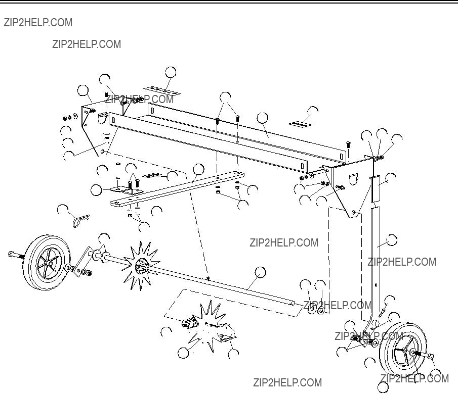


 16
16 
 15
15  18
18 


 15 16
15 16


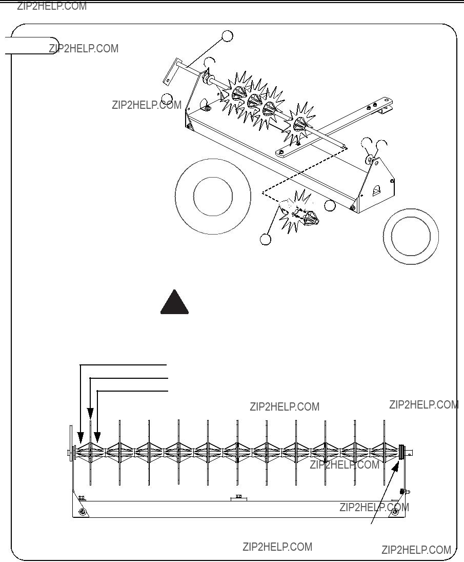
 27
27
 26 22
26 22 


 23
23
 23
23 
 6
6


 7
7