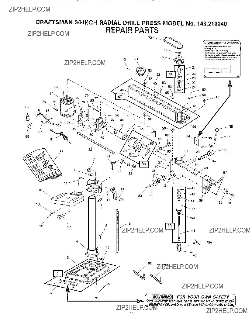
SERIAL

OR CODE

NUMBER:

Modelandcodenumbermaybefound on1herightsideofSpindieHousing

Youshouldrecordbothmodelandserial

numberandretainin a satepiacefor/ CRAFT M AN?? futureuse

CALIFORNIAOWNERS:a uniqueserial 34om OH RADmAL DRULL code numberis stampedinside the

PulleyCover

CAUTION:

Read All Instructions Carefully Before Start- ing Assembly and Use.

Save This Manual For

Future Reference.

o Assembly

?? Operation

o Repair Parts

o Warranty

SEARS, ROEBUCK AND CO., Hoffman Estates, la 60179, U.S.A.

FULL ONE-YEAR WARRANTY ON CRAFTSMAN RADIAL DRILL PRESS

If within one year from date of purchase, this Craftsman RADIAL DRILL PRESS fails due to a defect in materi- al or workmanship, Sears will repair it, free of charge

WARRANTY SERVICE IS AVAILABLE BY CONTACTING THE NEAREST SEARS STORE OR SERVICE

CENTER IN THE UNITED STATES,

. This warranty gives you specific legal rights and you may also have other rights that vary from state to state

Sears, Roebuck and Co., 13/817WA, Hoffman Estates, IL 60179.

GENERAL SAFETY RULES

KNOW YOUR POWER TOOL

For your own safety, read the owner's manual carefully Learn the application and limitations as well as the specific hazards peculiar to this tool

2 GROUNDING INSTRUCTIONS

A. All grounded, cord-connected tools:

In the event of a malfunction or breakdown, grounding pro- vides a path of least resistance for electric current to reduce the risk of electric shock This tool is equipped with an electric cord having an equipment-grounding conductor and a grounding plug The plug must be plugged into a

matching outlet that is properly installed and grounded in accordance with all local codes and ordinances

FOR POWER TOOLS

Extension Cords suitable for use with your Radial Drill

Press are available at your nearest Sears Catalog Order or Retail Store

Repair or replace damaged or worn cord immediately

S Grounded, cord-connected tools intended for use on a supply circuit having a nominal rating less than 150 volts:

Metal S_

rofGroundedII ['1)II

utlet Box

Do not modify the plug provided - if it will not fit the outlet, have the proper outlet installed by a qualified electrician

Improper connection of the equipment-grounding conduc* tot can result in a risk of electric shock The conductor with insulation having an outer surface that is green with or without yellow stripes is the equipment-grounding conduc- tor If repair or replacement of the electric cord or plug is

necessary, do not connect the equipment-grounding con- ductor to a live terminal

Check with a qualified electrician of serviceman if the grounding instructions are not completely understood, or if in doubt as to whether the tool is properly grounded

The use of any Extension Cord will cause some loss of power To keep this to a minimum and to prevent over- heating and motor buro-out, use the table below to deter?? mine the MINIMUM wire size (A W.G ) Extension Cord

Use only 3-wire extension cords :_hathave 3-prong ground- ing plugs, and 3-pole receptacles that accept the tool's plug

Grounding Pin

Adapter

Groundin(

Figure I - Wiring Methods

This tool is intended for use on a circuit that has an outlet that looks like the one illustrated in Sketch A in Figure 1, The tool has a grounding plug that looks like the plug illus- trated in Sketch A in Figure 1 A temporary adapter, which looks like the adapter illustrated in Sketches B and C, may be used to connect this plug to a 2-pole receptacle as shown in Sketch B if a properly grounded outlet is not available The temporary adapter should be used only until a properly grounded outlet can be installed by a qualified electrician The green-colored rigid ea_:, lug, etc extending from the adapter must be connected to a permanent ground such as a properly grounded outlet box

3 KEEP GUARDS IN PLACE

in working order and in proper adjustment and alignment,

2

4REMOVEADJUSTINGKEYSANDWRENCHES Formhabitof checkingto seethatkeysandadjusting wrenchesareremovedfromtoolbeforeturningon

5KEEPWORKAREACLEAN

Clutteredareas and beeches invite accidents

6DON'T USE IN DANGEROUS ENVIRONMENT

Don't use power tools in damp or wet locations, or expose them to rain Keep work area well illuminated_

7 KEEP CHILDREN AWAY

All visitors should be kept a safe distance from work area

8_ MAKE WORKSHOP KID PROOF

with padlocks, master switches, or by removing starter keys

9DON'T FORCE TOOL

It will do the job better and be safer at the rate for which it was designed

10 USE RIGHT TOOL

Don'tforce tool or attachment to do a job for which it was not designed

11 WEAR PROPER APPAREL

No loose clothing, gloves, neckties, nngs, bracelets, or jewelry to get caught in moving parts. Nonslip footwear is recommended Wear protective hair covering to contain long hair

12 ALWAYS WEAR SAFETY GLASSES

Also use face or dust mask if cutting operation is dusty Everyday eyeglasses only have impact resistant lenses They are NOT safety glasses

13 SECURE WORK

Use clamps or a vise to hold work when practical It's

safer than using your hand and frees both hands to oper- ate tool,

14_ DON'T OVERREACH

Keep your proper footing and balance at all times.

15 MAINTAIN TOOLS IN TOP CONDITION

Keep tools sharp and clean for best and safest perfor-

mance, Follow instructions for lubricating and changing accessories_

16 DtSCONNECT TOOLS FROM POWER SOURCE

before servicing and when changing accessories such as blades, bits, cutters, or when mounting and re-mounting motor

17, REDUCE RISK OF UNINTENTIONAL STARTING

Make sure switch is in "OFF" position before plugging in cord,

18 USE RECOMMENDED ACCESSORIES

Consult the owner's manual for recommended acces- sories Use of improper accessories may be hazard6us

19 NEVER STAND ON TOOL

Serious injury could occur if the tool is tipped or if the cut- ting tool is unintentionally contacted

20 CHECK DAMAGED PARTS

Before further use of the tool, a guard or other part that is damaged should be carefully checked to ensure that it will operate properly and perform its intended function - check for alignment of moving parfs, binding of moving parts, breakage of parts, mounting, and any other condi- tions that may affect its operation A guard or other part that is damaged should be properly repaired or replaced

21 DIRECTION OF FEED

Feed work into a blade or cutter against the direction of rotation of the blade or cutter only

22 NEVER LEAVE TOOL RUNNING UNATTENDED TURN POWER OFF Don't leave tool until it comes to a com- plete stop

The operation of any power tool can result in foreign objects being thrown into the eyes, which can result in severe eye damage_ Always wear safety goggles complying with ANSI

Z87,1 before commencing power tool operation. Safety Goggles are available at Sears retail or catalog stores

3

SAFETY RULES FOR DRILL PRESSES

1 DO NOT USE until unit is completely assembled and installed according to instructions

2 USE ONLY CHUCK KEY PROVIDED WiTH YOUR RADIAL DRILL PRESS It is equipped with a self-ejecting pin that elimi- nates hazard of leaving key in chuck

3 ALWAYS WEAR EYE PROTECTION

4 DO NOT WEAR Gloves, necktie or loose fitting ciothing

5 BE SURE DRILL BIT or cutting tool is securely locked in chuck

6 USE RECOMMENDED SPEED for drill accessory and workpiece material

7 ADJUST TABLE OR DEPTH STOP to prevent drilling into table work surface

8 NEVER USE YOUR HANDS TO HOLD workpiece during drilling Clamp it to work surface or use a vise to secure workpiece and prevent rotation

9 NEVER OPERATE drill press if any part is damaged or broken until it is properly repaired or replaced

10 NEVER pLACE YOUR FINGERS in a position where drill or cut- ting tool could contact them if part should shift unexpectedly

11 NEVER PERFORM LAYOUT, assembly or setup work on drill press with cutting tool rotating

12 SHUT OFF POWER, remove drill or cutting too!, and clean table before leaving machine

TABLE OF CONTENTS

TOOLS REQUmRED

8-inch Adjustable

UNPACKRNG AND CHECKUNG CONTENTS

Model 149213340 Radial Drill Press is shipped complete in one carton Carefully unpack and separate parts from packing material Check loose parts against Table of Loose Parts on page 5 and parts list on page 15 If any parts are missing or damaged, do not attempt to assemble Radial Drill Press, plug in power cord or turn on power switch until replacement parts are obtained and properly installed

Some parts such as the table and base are coated with rust preven- tative that can be removed with a soft cloth soaked in kerosene Do

not use acetone, gasoline, or lacquer thinner; these are dangerous

and may also damage the plastic and rubber parts of the Radial Drill

Press

Apply a coating of paste wax to the table and base work surfaces

I

TABLE OF LOOSE PARTS

ASSEMBLY

WARNING: FOR YOUR OWN SAFETY, NEVER CONNECT

THE RADIAL DRILL PRESS TO A POWER SOURCE UNTIL

ALL ASSEMBLY STEPS ARE COMPLETE_ AND YOU HAVE

READ AND UNDERSTOOD SAFETY AND OPERATIONAL

INSTRUCTIONS=

CAUTION: Do NOT ALLOW BRAKE FLUIDS_ GASOLINE,

PENETRATING OILS 1 ETC,_ TO COME IN CONTACT WITH

PLASTIC PARTS, THESE SOLUTIONS CONTAIN CHEMICALS

THAT CAN DAMAGE AND/OR DESTROY PLASTICS,

1Assemble Column and Flange Assembly (REF 4) to Base Assembly (REF 1) using four 8mm x 25mm bolts (REF 5).

2Slide Worm Pinion (REF 9) into Table Bracket (REF 6) until shaft extends from hole and teeth engage with Table Lift Gear (REF 7) Lower Vertical Rack (REF 15) into Table

Lift

Handle

Bracket making sure that the teeth are engaged in the Table Lift Gear inside bracket Slide rack and bracket assembly onto column until angled end at bottom of rack fits into top of column flange

Place Lift Handle (REF 10) on Worm Pinion Shaft extending from Table Bracket Align flat on pinion shaft with set screw (REF 11) and tighten

NOTE: Before installing drill head assembly, find a per- manent location for radial drill press and fasten base down using Carriage Bolts (REF 96) and Wing Nuts (REF

97)provided. BE SURE BOLTS PASS ENTIRELY

THROUGH MOUNTING SURFACE. (See Installing Radial Drill Press section on page 7,)

4Race Lock Shoe (REF 88) from loose parts bag into cast pocket in Column Head Assembly (REF 83) then slide Column Head Assembly with Drilt Head Assembly down onto Column as shown Be very careful to hold Lock Shoe in place during assembly to prevent it from falling down inside column Be sure to engage Vertical Rack with angle on bottom of Column Head Drill head should rotate freely around column

Lock

Lock

Handle

Handle

Bar

Lift

5Attach one Lock Handle (REF 14) to Table Bracket and two Lock Handles to Column Head_

6, Attach three Handle Bars (REF 37) into threaded holes on head of Feed Shaft Assembly (REF 34)

Table Bracket

f

I

7Make sure bottom of Spindle Shaft (REF 42) and bore of Chuck (REF 46) are clean and free of grease Press Chuck up onto Spindle Shaft_

NOTE: To avoid damage to Chuck, rotate Chuck barrel until jaws are fully open.

8Using a mallet or a block of wood and hammer, firmly tap Chuck upward into position onto Spindle Shaft

nNSTALUNG RADUAL DRULL PRESS

WARNING: BEFORE USING RADIAL DRILL PRESS_

MAKE SURE IT IS ATTACHED TO A FIRM AND STABLE SUP-

PORT SURFACE USING CARRIAGE BOLTS AND WING

NUTS PROVIDED.

12 3/4" Fore and Aft Travel

1Choose an area that allows sufficient clearance to take full advantage of the Radial Drill Press's lateral, rota- tional, and tilt motions

2Bolt Radial Drill Press to a firm and stable surface using

Carriage Bolts and Wing Nuts provided, Be sure bolts pass entirely through mounting surface and are at least 5/16-18 standard strength_ Tighten all bolts and wing nuts securely

3/8" Diameter

2 Hotes

Head Tilts 45"

C_ockwise and 90"360" Rotation

Counter-clockwise

6 1/4"

Use Carriage Bolts and

Wing Nuts Provided

7

CONTROLS AND ADJUSTMENTS

AND POWER CORD IS UNPLUGGED BEFORE PERFORMING

_ WARNING: MAKE SURESWITCHIS IN OFF POSmON

CHECKS= ADJUSTMENTS I OR SETUP PROCEDURES,

2.Table Rotation - To rotate table, first loosen Lock Handle. The table can be rotated from side to side or completely out from under Spindle Shaft to allow work surface on base to support workpiece_

On-Off Switch

The ON-OFF switch (REF 59) is located on front of Drill Head

and has operating positions clearly marked_ Push switch up to turn tool ON and down to turn it OFF. The switch has a

Switch Key (REF 60) that, when removed, allows switch to be locked in OFF position. To activate locking feature, push switch to OFF and pull Switch Key out of switch.

Depth Stop Adjustment

When it is desirable to drill holes to an exact depth, the built- in depth stop can be set

1With Radial Drill Press turned OFF, adjust table height until driUbit barely touches workpiece at spot to be drilled, and lock into position

2.Loosen Depth Stop Butterfly Set Screw (REF 36) and rotate Depth Gauge Assembly (REF 35) until desired drill depth on Scale aligns with Pointer on Spindle Housing (REF 25). Tighten Butterfly Set Screw_

Butterfly Set Screw

Spindle Return Spring Adjustment

Table Adjustment

1_ Table Height - To raise or lower Table, loosen Lock Handle on back of Table BrackeL Crank Lift Handle to raise or lower Table, then lock position with Lock Handle

An automatic spindle Return Spring (REF 28) is installed in Drill Head to return spindle to full up position. This spring was preset at the factory and should not be readjusted

unless absolutely necessary. Adjust Return Spring as fol- lows:

1Loosen two Nuts (REF 29 & 30) on side of Spring Assembly (REF 28) about 1/4" NOTE: Do not remove these nuts from Feed Shaft (REF 34).

2Hold Spring Assembly firmly and pull it out away from side of Drill Head Rotate Spring Assembly until next notctl engages with cast tab on side of Drill head.

8

3Check operation of Return Spring for proper tension and full return

4Nuts must be tightened before use Be very careful; the nuts hold Spring Assembly in position and should NOT be tightened flush against Spring Assembly A small gap is necessary for proper operation of Spindle Housing Lock the two nuts together using separate wrenches and make sure Spindle Housing moves freely up and down

Spindle Speeds

Your Radial Drill Press has a 1725 RPM motor with five spin- dle speeds available through a pulley/belt drive The various

PulleyCover

\

Butterfly Set Screw

SPnNDLE SPEED CHART

spindle speeds are required for different materials, different types and sizes of drills, and different cutting tools

Refer to the V-belt placement illustration on this page fo_ the five available spindle speeds Maximum speed is obtained when V-belt is on largest step of pulley at motor end and smallest step of pulley at spindle end

Changing Speeds

_ WARNING: DISCONNECT RADIAL DRILL PRESS FROM

POWER SOURCE BEFORE CHANGING SPEEDS,

1 Open Pulley Cover (REF 48)

2Position V-belt (REF 73) on desired steps of Spindle Pulley (REF 19) and Motor Pulley (REF 71) When posi- tioning V-belt, always start by moving the end of the belt that will go from a larger step to a smaller step first

3A chart (REF 51) of drill speeds and pulley steps is pro- vided below and inside Pulley Cover for convenience

Belt Tension Adjustment

NOTE: The Radial Drill Press is shipped with the V-belt installed, Check V-belt adjustment for proper tension before use.

1, Open Pulley Cover (REF 48)

2Loosen belt tension Butterfly Set Screw (REF 36) located on right side of Cover Mount (REF 75)

3_ Select speed for drilling operation by referring to Speed Chart (REF 51) inside Pulley Cover or on bottom of page Move V-belt to correct position for desired speed

4Push motor towards rear of machine until V-belt sides are straight between pulleys

9

Belt Tension

Butterfly Set

Screw

NOTE: When properly tensioned, V-belt should deflect about 1/2" under thumb pressure at mid-point between pulleys.

5Tighten belt tension Butterfly Set Screw and close Pulley Cover

Tilting Drill Head

The Drill head can be tilted to drill up to 45 degrees clockwise and 90 degrees counter-clockwise of vertical To tilt Drill head, loosen Lock Handle on right side of Column head and pull out and turn plunger of Vertical Lock (REF 87) Use

Angle Gauge (REF 85) on Column head and full length scored V groove on Horizontal Tube (REF 81) to set desired angle Lock in position using Lock Handle When returning to vertical position, turn Vertical Lock plunger and allow it to snap down onto Horizontal Tube When vertical position is reached, plunger will pop into milled slot on Horizontal Tube Tighten Lock Handle to lock position

Rotating Drill Head

The Drill head can rotate 360 degrees around the Column Take care when mounting Radial Drill Press to allow suffi- cient clearance for full use of this feature. Loosen Lock Handle on left lower area of Column Head. Rotate to desired

position and lock in place with Lock Handle

Tilt Lock

Handle

Scored

V Groove

Lock

Handle

Vedical

Lock

Moving Drill Head In or Out

The Drill head can move in or out along Horizontal Tube (REF 81) to drill large objects or move between holes without unclamping workpiece. Loosen same Lock Handle as for tilt- ing Drill head above Use Horizontal Feed Knob (REF 89) to move Drill head in or out to desired position Lock in place with Lock Handle before drilling to prevent drill bit from "walk- ing" along the wotkpiece surface

10

Adjusting Spindle Perpendicular to Table

The Radial Drill Press was factory-adjusted and set with Spindle Housing perpendicular to table No further adjust- ment should be necessary However. normal shipping and handling may have changed the setting Check and adjust as follows:

1 DISCONNECT FROM POWER SOURCE! Never make any adjustments while the tool is plugged in

2Be sure the Vertical Lock plunger (REF 87) is engaged in Horizontal Tube slot (REF 81).

3Mount a 3" long precision round steel rod or a large, straight drill bit into Chuck and place a combination

square on Table Check alignment between rod and Table as shown

NOTE: Combination square must be "true," Check for accuracy as illustrated below.

Flip Square Over to Dotted Position--Edge of

Scale Should Align Perfectly with Drawn Line

Precision

Steel Rod

4If out of square, loosen two Set Screws (REF 26) that attach Spindle Housing Assembly (REF 25) to Horizontal Tube Tilt Spindle Housing Assembly until rod is exactly 90 degrees to Table Tighten both Set Screws

5Check V-belt tension after this adjustment and readjust if required

Alignment of Motor Pulley to Spindle Pulley

Check pulley alignment by sighting between tops of Spindle Pulley (REF 19) and Motor Pulley (REF 71)

1Should they need adjustment, loosen screws on Cover Mount (REF 75) and turn motor assembly until pulleys align,

2 Tighten screws and adjust V-belt tension if needed

11

OPERATaON

Correct Drilling Speeds

See "Changing Speeds" section under "Controls and Adjustments" and Speed Chart inside Pulley Cover for cor- rect drilling speeds Always disconnect tool from power source before making any adjustments Care must be taken when setting speed for any cutting tool or accessory not list- ed on chart Read and follow any speed instructions supplied with cutting tool or accessory Rules for judging drilling speed for materials not listed in chart are:

1A small size drill requires faster cutting speeds than a larger size

2.Soft material requires faster speeds than hard material

See "Accessories" section for a listing of items authorized for use with this tool.

Drilling Wood

Many types of drill bits designed for drilling or boring wood can be used with this machine_ Standard high speed twist drills intended primarily for metal drilling work very well on wood_ Spur bits, sometimes referred to as forstner bits, are best for woodworking because they cut a clean-sided, flat

bottomed hole Be careful NOT to use any SCREW TIP hand drill bit At even the slowest drill press speeds, this style will lift the workpiece from the table and could easily cause

injury.

Feed bit slowly through wood As bit is about to cut through bottom surface, slow feed even more to prevent splintering or a burr to bottom face of workpiece Always use a piece of scrap wood under workpiece to reduce splintering and to pro- tect drill bit and work table

Use of clamps or a work vise is recommended for most drilling operations If a method of clamping is not used, brace back-up material against left side of column to prevent work- piece from spinning

Drilling Metal

Although primarily a woodworking tool, this Radial Drill Press can be used to drill metal. Always firmly clamp or use a drill press vise bolted to work table when drilling metal.

MAINTENANCE

POWER AND DISCONNECT TOOL FROM POWER SOURCE

WARNING: FOR YOU OWN SAFETY_ TURN OFF

BEFORE PERFORMING ANY MAINTENANCE.

Periodically clean dust accumulation from machine Apply a light coat of paste wax to table, base work surfaces, and ver- tical and horizontal columns. This will help to keep them clean and working smoothly=

All of the ball bearings are packed with grease at the factory and require no further lubrication The Quill and Spindle Rack

should be lubricated periodically with a light machine or pen- etrating oil Open Pulley Cover and spray a light coat of oil on Spindle Shaft splines (REF 42) as you move spindle up and down Avoid getting any oil on the drive belt Also, with spindle in fully down position, spray a light coat of oil on Quill (REF 40). A small amount of grease on Table Lift Gear (REF 7) and Horizontal Feed Gear (REF 90) will keep these two mechanisms moving freely Wipe excess grease from racks to prevent dust buildup in teeth

12

ACCESSORUES

Mortising Kit

Although not designed specifically for mortising, the variety of possible drill angles and feed lengths with the Radial Drill Press make possible some formerly impossible operations Use Sears Model 9 BT 25255 Mortising Chisel Housing and Model 9 BT 29506 Drill Press Mortising Kit with the accompa-

nying made-to-fit bits available through Sears Catalog and Retail Stores

Vises and Clamps

A large variety of sizes and types of drill press vises and clamps are available through Sears Catalog and Retail Stores The work table has slots that will align with most vises

Forstner Bits

A selection of standard size forstnar bits is available to fit the

1/2" capacity chuck of the Radial Drill Press Sears Check with your local Catalog and Retail Stores

13

CRAFTSMAN 344NCH RADIAL DRILL PRESS MODEL No. 149.213340

REPAnR PARTS

72 71

53

89 :

7 14

34

54

88

---i 87

14/__6

30 29

15

4I

\I

3

14

CRAFTSMAN 34-iNCH RADIAL DRULL PRESS MODEL No. 149.213340

PARTS LIST

BEF

NO. PARTNO. DESCRIPTION

514910-253-00 i BELTSPEEDLABEL

524920-050-70 PULLEYC0VER KNOB

53ST0511003 810-24 X 3/8" PAN HEADSCREWS

54ST0551210 810 STARWASHER

55STD55!010 810 FLATWASHERS

561789-015-00i 810 RUBBERWASHERS

57STD511007 8t0-24 X 3/4" PAN HEADSCREWS

584920-040q0 SWITCHCOVER

592292-067-00 DPSTSWITCH (INCLUDES60)

602292-068-00 SWITCH KEY (ORDERFOR KEY ONLY)

61STD364949 POWERCORD

62t708-100-00 M5 X 8ram PAN HEADSCREWS

864910-i350-00 WIRECLAMPS (HEYCO#3355)

4910-351-00 RIGHTANGLE BUSHING (HEYCO81327)

65STD375005 WIRE NUT

664910-353-70 SWITCH CORD

874910-354-00 CABLE TIES

884910-355-00 FULL INSUL FEMALE TERM, 90 DEGFLAG

80 4910-220-00 MOTOR.EMERSON1/3 HP MAXIMUM

70STD580100 1/8 X 1" SQUAREDRIVEKEY

714910-080-70 MOTORPULLEY

78 1709-125-00 M6 X 6mm SOCKETHEADSET SCREW

73 STD303590 V-BELT..._

74 4910-031-70 MOTORBRACKET

75 4910-030-09 COVERMOUNT

70 4910-050-70 PUSHTEE

77 49!0-120-70 SPRING

78ST05231!0 5/16-17X I" HEX HEAD BOLTS

79STD541431 5/16-18HEX LOCK NBTS

80ST0551031 5/16 FLAT WASHERS

814910q61-70 HORIZONTAL TUBE

824910-166-70 HORIZONTAL RACK

834910-020-95 COLUMN HEAD ASSEMBLY (INCLUDES53.84.85

044910-020-09 COLUMN HEAD

85 4910-021-70 ANGLE GAUGE

88 1785-050-00 M16 HEXJAM NUT

87 4910-059-70 VERTICALLOCK

881175-000-00 LOCk SHOEWlTH RECESS

894910-051o70 HORIZONTALFEEDKNOW ASSEMBLY

9049t0-017-70 HORIZONTALFEEDGEAR

91STD501002 810-24 X 1/4" SOCKETBETSCREW

98 STD582037 EXTERNALRETAININGRiNG

931697-010-00 #4 X 1/4" DRIVESCREWS

944920-250-00 WARNING LABEL/DATA PLATE

954920-252*00 OWNER'SMANUAL

98 ST0533150 5/t6q8 X 5" CARRIAGEBOLTS

97 ST0541631 5/16-18WING NUTS

982288-000-00 5/32" HEX HANDLE

994910-19!-00 3mm HEX HANDLE

1001175-001-00 LOCK SHOE

QTY.

1

1

8

1

4

4

3

1

1

1

3

3

2

1

1

2

!

1

I 1 1 1 1 1 1

!

6

6

13

1

1

1

1

1

1

1

1

1

1

1 t 4 1 1 2 2 1 1 1

15

34-BNCH RADBAL DRILL PRESS

Now that you have purchased your Radial Drill Press should a need ever exist for repair parts or service, simply contact any Sears Service'Center or most Sears, Roebuck and Co stores, Be sure to provide all pertinent facts when you call or visit

WHEN ORDERING REPAIR PARTS, ALWAYS GIVE THE FOLLOWING

INFORMATION:

All parts listed may be ordered from any Sears Service Center and most

Sears stores

If the parts you need are not stocked locally, your order will be electroni- cally transmitted to a Sears Repair Parts Distribution Center for handling

SEARS, ROEBUCK AND CO., Hoffman Estates, IL 60179, U.S.A.

Printed in USA