Standalone RFID
Access Controller
user manual
imagine the possibilities
Thank you for purchasing this Samsung product. To receive more complete service,
please visit our website.
www.samsungsecurity.com
Standalone RFID
Access Controller
user manual
imagine the possibilities
Thank you for purchasing this Samsung product. To receive more complete service,
please visit our website.
www.samsungsecurity.com

safety information
CAUTION
RISK OF ELECTRIC SHOCK.
DO NOT OPEN
CAUTION: TO REDUCE THE RISK OF ELECTRIC SHOCK, DO NOT REMOVE COVER (OR BACK) NO USER SERVICEABLE
PARTS INSIDE. REFER SERVICING TO QUALIFIED SERVICE PERSONNEL.
This symbol indicates that dangerous voltage consisting a risk of electric shock is present within this unit.
This exclamation point symbol is intended to alert the user to the presence of important operating and maintenance (servicing) instructions in the literature accompanying the appliance.
WARNING
??? To reduce the risk of ???re or electric shock, do not expose this appliance to rain or moisture.
WARNING
1.Be sure to use only the standard adapter that is speci???ed in the speci???cation sheet. Using any other adapter could cause ???re, electrical shock, or damage to the product.
2.Incorrectly connecting the power supply or replacing battery may cause explosion, ???re, electric shock, or damage to the product.
3.Do not connect multiple controllers to a single adapter. Exceeding the capacity may cause abnormal heat generation or ???re.
4.Securely plug the power cord into the power receptacle. Insecure connection may cause ???re.
5.When installing the controller, fasten it securely and ???rmly. The fall of controller may cause personal injury.
6.Do not place conductive objects (e.g. screwdrivers, coins, metal parts, etc.) or containers ???lled with water on top of the controller. Doing so may cause personal injury due to ???re, electric shock, or falling objects.
7.Do not install the unit in humid, dusty, or sooty locations. Doing so may cause ???re or electric shock.
8.If any unusual smells or smoke come from the unit, stop using the product. In such case, immediately disconnect the power source and contact the service center. Continued use in such a condition may cause ???re or electric shock.
9.If this product fails to operate normally, contact the nearest service center. Never disassemble or modify this product in any way. (SAMSUNG is not liable for problems caused by unauthorized modi???cations or attempted repair.)
10. When cleaning, do not spray water directly onto parts of the product. Doing so may cause ???re or electric shock.
CAUTION
1.Do not drop objects on the product or apply strong blows to it. Keep away from a location subject to excessive vibration or magnetic interference.
2.Do not install in a location subject to high temperature (over 50??C), low temperature (below
3.If you want to relocate the already installed product, be sure to turn off the power and then move or reinstall it.
4.Remove the power plug from the outlet when there is a lighting storm. Neglecting to do so may cause ???re or damage to the product.
2_ Safety information

5.Keep out of direct sunlight and heat radiation sources. It may cause ???re.
6.Install it in a place with good ventilation.
7.Avoid aiming the controller directly towards extremely bright objects such as sun.
8.Apparatus shall not be exposed to dripping or splashing and no objects ???lled with liquids, such as vases, shall be placed on the apparatus.
9.The Mains plug is used as a disconnect device and shall stay readily operable at any time.
FCC Statement
This device complies with part 15 of the FCC Rules. Operation is subject to the following two conditions :
1)This device may not cause harmful interference, and
2)This device must accept any interference received including interference that may cause undesired operation.
Caution
This equipment has been tested and found to comply with the limits for a Class A digital device, pursuant to part 15 of FCC Rules. These limits are designed to provide reasonable protection against harmful interference when the equipment is operated in a commercial environment.
This equipment generates, uses, and can radiate radio frequency energy and, if not installed and used in ac- cordance with the instruction manual, may cause harmful interference to radio communications. Operation of this equipment in a residential area is likely to cause harmful interference in which case the user will be required to correct the interference at his own expense.
IMPORTANT SAFETY INSTRUCTIONS
1.Read these instructions.
2.Keep these instructions.
3.Heed all warnings.
4.Follow all instructions.
5.Do not use this apparatus near water.
6.Clean only with dry cloth.
7.Do not block any ventilation openings. Install in accordance with the manufacturer???s instructions.
8.Do not install near any heat sources such as radiators, heat registers, or other apparatus (including ampli???ers) that produce heat.
9.Do not defeat the safety purpose of the polarized or
10.Protect the power cord from being walked on or pinched particularly at plugs, convenience receptacles, and the point where they exit from the apparatus.
11.Only use attachments/accessories speci???ed by the manufacturer.
12.Use only with cart, stand, tripod, bracket, or table speci???ed by the manufacturer, or sold with
the apparatus.
13.Unplug this apparatus when a card is used. Use caution when moving the cart/ apparatus  combination to avoid injury from
14.Refer all servicing to quali???ed service personnel. Servicing is required when the apparatus has been damaged in any way, such as powersupply cord or plug is damaged, liquid has been spilled or objects have fallen into the apparatus, the apparatus has been exposed to rain or moisture, does not operate normally, or has been dropped.
 INTRODUCTIONINFORMATIONPRODUCTSAFETY
3

contents
INSTALLATION AND EXTERNAL
CONNECTION
9
SYSTEM INITIALIZATION & BASIC
OPERATIONS
12
PRODUCT SPECIFICATIONS
15
9 Installation
9Bypass Diode Connection
10I/O Connection
12Initializing the system by
12Basic Operations
13To register /delete Master ID
13 To register/delete ID card
15 Product Speci???cations

product introduction
FEATURE
This product is designed for use with
And it is also featured by the
???125 kHz Proximity Access Controller
???Up to 512 users including one Master ID can be registered
???Standalone (no application S/W required)
???Direct Control of the Door Lock
???Can select a lock device type from Power Fail Safe and Power Fail Secure
???Epoxy Molding
???Weatherproof
 INTRODUCTION PRODUCT
5
product introduction
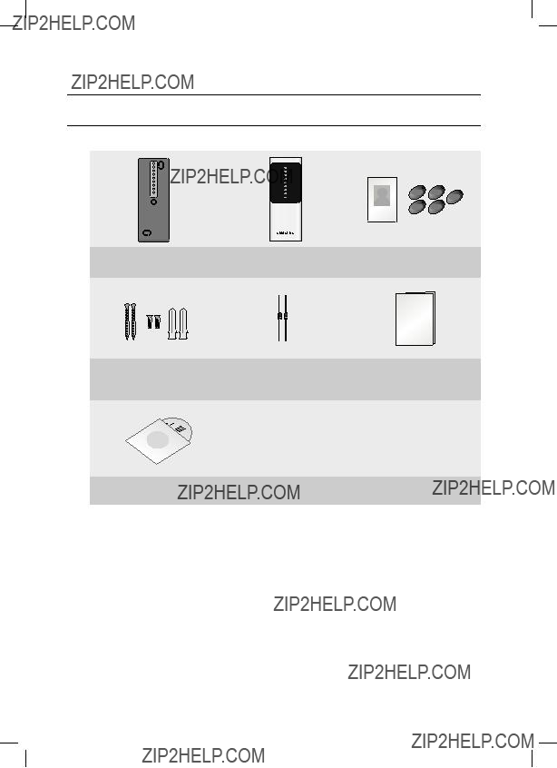
WHAT???S INCLUDED
Check if the following items are included in the product package.
t??????????Gj??????
Master Card (x1)
Keytag (x5)
CD Manual
6_ Product Introduction

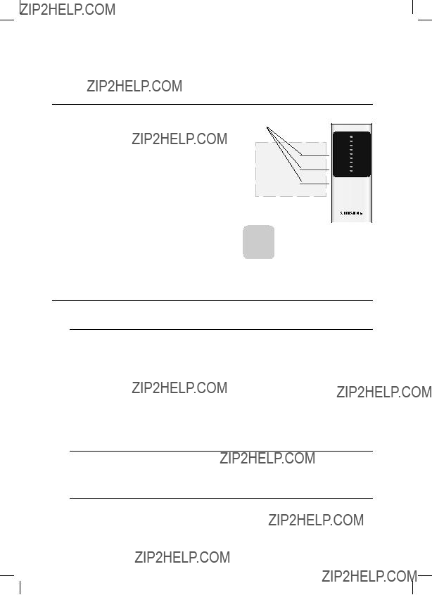
AT A GLANCE
Front/Rear
3
4
5
 INTRODUCTION PRODUCT
7

product introduction
CABLE COLOR SCHEME
CABLE SELECTION
8_ Product Introduction

installation and external connection
INSTALLATION
10
44.4  1/2??? hole
40.6 Reader Module
8.5
- On a doorframe or the wall
1.Drill a
2.Drill two
3.Insert the reader module cable into the center hole and secure the module using two screws inserted in the upper right and the bottom left corner, respectively.
4.Insert the bezel of
CONNECTION EXTERNAL AND INSTALLATION
BYPASS DIODE CONNECTION
If you connected an inductor (door lock or alarm device) to the output relay, there should occur a voltage surge while the inductor was between turning on and turning off. If you do not connect a reverse diode to the relay, the voltage surge will cause damage to the electric circuit of the controller. To reduce this surge, it is recommended to connect the bypass diode to the relay.
9

installation and external connection
I/O CONNECTION
Input Connection
Door Contact Sensor
Exit Button
DC 12V(+) POWER
- To connect the power supply unit
1.Connect the DC+12V to the red line.
2.Connect GND to the black line.
- To connect the Door Contact Sensor
1.Connect the COM port of the sensor to the blue line.
2.Connect the NO port of the sensor with the GND line.
- To connect the Exit Button
1.Connect one end of the button to the green line.
2.Connect the other end of the button to GND.
10_ Installation and External Connection
Output Connection
ALARM OUT (purple)
Alarm Device
Lock Type Select
(yellow)
Cathode Anode
DC 12V(+) POWER
- To connect the power supply unit
1.Connect the DC+12V to the red line.
2.Connect GND to the black line.
- To connect the door lock device
1.Connect the plus(+) line of the lock device to DC+12V.
2.Connect the
- To connect the alarm device
1.Connect the plus(+) line of the alarm device to DC+12V.
2.Connect the
- To specify the lock type
POWER FAIL SAFE: Connect the yellow line to GND.
POWER FAIL SECURE: Leave the yellow line in the ???oating state.
CONNECTION EXTERNAL AND INSTALLATION
11
system initialization & basic operations
INITIALIZING THE SYSTEM BY
White
Door Lock
Green
Exit Button
Lock Type
Yellow
M ??? If you initialize the system, all of the data settings will return to the factory default.
BASIC OPERATIONS
When the power is supplied
1.All of the LED indicators will turn red or green, and repeat turning ON/OFF twice before being completely turned OFF. In the
2.You will hear a beep once.
When you present a registered card to the product or press the Exit button
1.All LED indicators turn from red to green, and turn off top down in sequence before turning back red.
2.Then, the door stays open for the speci???ed time with the upper two indicators turning green, which indicates the door is open.
3.You will hear a beep once.
When you present an unregistered card to the product
1.All LED indicators turn red, and repeat turning on/off twice before staying in ON.
2.You will hear a beep twice.
When you present a user card to the product while the door is open
1.The two LED indicators from the top stay green, indicating the door is open; in the mean time, the other indicators re???ect the authentication results.
12_ System Initialization & Basic Operations

TO REGISTER /DELETE MASTER ID
1.First turn off the product, and
2.When you turn the product back on, you will hear the beep twice while all of the LED indicators turn red, and repeat turning on/off twice before being completely ON; then the Master card will be deleted.
3.Upon deletion of the Master Card, you will hear a beep once and all of the LED indicators toggle between green and red twice before turning off; in this condition, they turn red from bottom up in sequence.
Cable
Blue
Yellow
Green
Purple
White
Red
DC12V
BASIC & INITIALIZATION SYSTEM
5.When you turn the product back on, it recognizes and registers the
M ??? If you present a registered user card after the Master Card is deleted, that card will be registered as the Master Card.
TO REGISTER/DELETE ID CARD
1. If you present the Master Card to the product, it will sound the beep once and the ???rst three LED indicators from the top will turn green from the top.
MASTER CARD
2.If you present a new user card to the product, it will sound the beep once and all of the LED indicators except for the ???rst three ones from
the top will turn from red to green. Then, they all turn off and turn  back on bottom up in sequence. When all of the LED indicators turn
back on, they will turn red except for the ???rst three LED indicators from the top . Then, the user card will be registered.
3.If you present a registered user card, the product will sound the beep twice and all LED indicators except for the ???rst 3 from the top will turn red, and repeat turning on/off twice before being completely ON. Then the user card will be deleted.
4.When you present the Master Card to the product after the user card is deleted, the product will sound the beep once and all of the LED indicators turn red, starting with the ???rst three LED indicators from the top turning from green to red.
M ??? If you present a registered user card after the Master Card is deleted, that card will be registered as the Master Card.
OPERATIONS
13

troubleshooting
TROUBLESHOOTING
If the product does not function properly, please see the below for trouble shooting. If the trouble persists, please contact the SAMSUNG Customer Service near you.
14_ troubleshooting

product speci???cations
PRODUCT SPECIFICATIONS
SPECIFICATION PRODUCT
15
Correct Disposal of This Product (Waste Electrical & Electronic Equipment)
(Applicable in the European Union and other European countries with separate collection systems)
This marking on the product, accessories or literature indicates that the product and its electronic accessories (e.g. charger, headset, USB cable) should not be disposed of with other household waste at the end of their working life. To prevent possible harm to the environment or human health from uncontrolled waste disposal, please separate these items from other types of waste and recycle them responsibly to promote the sustainable reuse of material resources.
Household users should contact either the retailer where they purchased this product, or their local government office, for details of where and how they can take these items for environmentally safe recycling.
Business users should contact their supplier and check the terms and conditions of the purchase contract. This product and its electronic accessories should not be mixed with other commercial wastes for disposal.
Correct disposal of batteries in this product
(Applicable in the European Union and other European countries with separate battery return systems.)
This marking on the battery, manual or packaging indicates that the batteries in this product should not be disposed of with other household waste at the end of their working life. Where marked, the chemical symbols Hg, Cd or Pb indicate that the battery contains mercury, cadmium or lead above the reference levels in EC Directive 2006/66. If batteries are not properly disposed of, these substances can cause harm to human health or the environment.
To protect natural resources and to promote material reuse, please separate batteries from other types of waste and recycle them through your local, free battery return system.