[ SALES NETWORK ]
B W CCD CAMERA
INSTRUCTION MANUAL
??SAMSUNG TECHWIN CO., LTD
OPTICS & DIGITAL IMAGING DIV.
SUNGNAM,
TEL : 82 -
FAX: 82 - 031- 740 - 8145
??SAMSUNG
40 SEAVIEW DIRVE, SECAUCUS N.J 07094, U.S.A.
TEL :
FAX :
SAMSUNG CCD CAMERA
[ SALES NETWORK ]
B W CCD CAMERA
INSTRUCTION MANUAL
??SAMSUNG TECHWIN CO., LTD
OPTICS & DIGITAL IMAGING DIV.
SUNGNAM,
TEL : 82 -
FAX: 82 - 031- 740 - 8145
??SAMSUNG
40 SEAVIEW DIRVE, SECAUCUS N.J 07094, U.S.A.
TEL :
FAX :
SAMSUNG CCD CAMERA

Thank you for purchasing a SAMSUNG CCD CAMERA. Before operating the camera, confirm the camera model and
proper input power voltage. In order that you can understand this manual thoroughly, we'll introduce our model description.
???Signal System
E  EIA Model C
  CCIR Model
???Power Source
A AC 24V ~
D  DC 12V
H  High Voltage (CCIR Model: AC 230V~ )
The lightning flash with arrowhead symbol, within an equilateral triangle is intended to alert the user to the presence of uninsulated "dangerous voltage" within the product's enclosure that may be of sufficient magnitude to constitute a risk of electric shock to persons.
The exclamation point within an equilateral triangle is intended to alert the user to the presence of important operating and maintenance (servicing) instructions in the literature accompanying the appliance.
4 B W CCD CAMERA
WARNING- TO PREVENT RISK OF FIRE OR ELECTRIC SHOCK,
DO NOT EXPOSE THIS CAMERA TO RAIN OR MOISTURE.
INFORMATION
Operation of this equipment in a residential area is likely to cause harmful interference in which case the user will required to correct the interference at his own expense.
WARNING - Changes or modifications not expressly approved by the manufacturer could void the user???s authority to operate the equipment.
CAUTION : To prevent electric shock and risk of fire hazards:
 Do NOT use other than specified power source.
  Do NOT expose this appliance to rain or moisture.
This installation should be made by a qualified service person and should conform to all local codes.
B W CCD CAMERA 5

Features
Automatic Backlight Compensation
The backlight compensation technology allows the camera to find the best picture conditions in any environment and automatically gives a necessary light level compensation, so that you can always obtain the clear picture, the finest detail and perfect light contrast.
High Resolution
The horizontal resolution of 570 TV lines can be achieved by using a high density CCD
having effective 410,000 pixels, which provides clean, noiseless and reliable pictures.
Electronic Iris
Electronic iris shutter is automatically controlled at the speed of 1/60~1/100,000sec (EIA models), 1/50~1/100,000sec (CCIR models).
Video / DC Selection Switch
The camera accepts 2 types of auto lris lenses (DC type/Video type) and is set with Video/ DC selection switch.
SYNC. System
You can select INT(Internal Synchronization) mode or L. L(Linelock Synchronization) mode.

Precautions
It can cause malfunctions to occur.
Do not expose the camera to rain or spill beverage on it.
If it gets wet, wipe it dry immediately. Liquids can contain minerals that corrode the electronic components.
It can damage the CCD.
Do not touch the front glass of the camera.
It is one of the most important parts of camera. Be careful not to be stained by fingerprint.
Do not disassemble the camera.
There are no
Notes: ???If the camera is exposed to spotlight or object reflecting the strong light, smear or blooming may occur.
???Please check the power whether it satisfies the normal specification before connecting the camera.
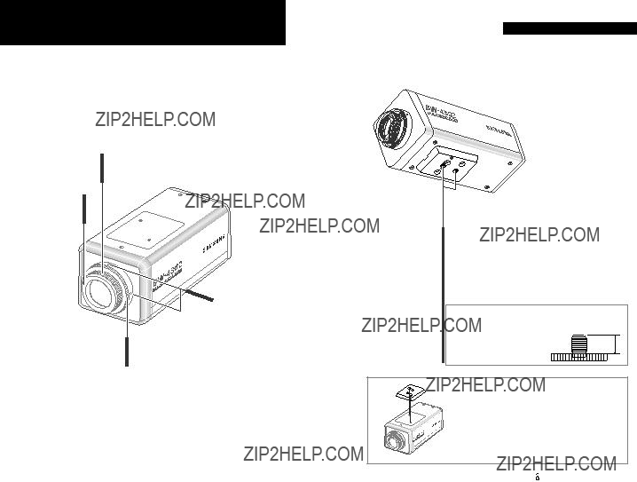
Getting to Know Your Camera
Getting to Know Your Camera
???C - Mount Lens Adapter
??? Glass Protecting Cap
??? Back Focus
Lock Screw
??? CS- Mount Lens Adapter
Tripod Mounting Hold
Used to install the camera on an optional tripod. The tripod must be equipped with the screw specified as shown below
L : 4.5mm ??0.2 mm (ISO standard), or 0.197???(ASA standard)
L
You can remove and install this bracket on the top of the camera.
You must use the supplied screw or the equivalent
(within 5mm). If not, it can cause malfunction and demage inside the camera.

Back
Accessories
 IRIS Mode
Selection Switch.
 Video Out Jack
 Auto Iris Lens Connector
 SYNC Mode selection switch
Notes:There is no Sync selection switch on the rear of DC power type.
High Voltage type (4302CH)
IRIS lens plug
 BLC Function select Switch
 LEVEL Adjustment V.R
(Using DC Iris Lens Only!)
 Power Input Terminal
Notes: Each model has the different power source.
 V.PHASE Adjustment V.R
Notes: There is no V.PHASE VR on the rear of DC power type.
Instruction
Manual

Controls and Adjustments
 Glass Protecting Cap
Be sure to cap the lens mount when the lens is not mounted. Pull out the cap to remove.

Used to mount a

Used to mount a
 Back Focus Lock Screw
Used to readjust backfocus of the camera. There are two backfocus lock screws. These must be loosened before the camera may be back focused. Loosen lock screw using the
 Tripod Mounting Hole
This screw hole is used to install the camera on a mount. The camera can be installed on a tripod or other camera mount either from the top or the bottom by using the 1/4??? - 20UNC threaded holes in the camera. For details, see page 11.
 Video Out Jack
Connect to the video input connector of monitor. This jack outputs a composite video signal. Use a coaxial cable for connection.
 Auto lris Lens Connector
Used to connect auto iris lens plug. Be sure to use
Controls and Adjustments
 SYNC Mode Selection Switch
Used to choose INT or LL mode.
 SYNC (Synchronization) Mode
INT(Internal) mode : The camera may be operated independently with its internal crystal control.
LL(Linelock) mode : It synchronizes the video signal between cameras using the frequency of the AC power supply without external synchronous generator.
Notes :  The LL mode can be used in the areas of 60Hz(EIA models) and 50Hz(CCIR models).
 There is no SYNC selection switch on the rear of DC power type.
 V. PHASE Adjustment V. R
If camera is to be used in the LL mode, the vertical phase may require adjustment to synchronize the vertical phase of the camera with other camera in the system.
Make this adjustment when the vertical phase of the camera does not match with other cameras or systems. For correct adjustment, use a multi- channel oscilloscope. The V adjustment has been set at 180 degrees and can be readjusted in the range of 0 to 270 degrees.
Notes :  This adjustment is necessary only when line lock sync operation is performed.
 There is no V. PHASE V.R on the rear of the DC power type.
Power Input Terminal
Used to connect AC/DC power source. For details, see page 23.
Notes : Each model has the different power source, you must confirm appropriate power source of your camera.
 Level Adjustment V. R (Using DC Iris Lens Only!)
Used to adjust video output level. When the brightness control of the monitor does not operate correctly, you can get the optimum picture by controlling the Video output level of camera.

Controls and Adjustments
Notes : This function is activated when being in the ESC mode.
 BLC(Backlight Compensation) Function CENTER/FULL Switch
This switch improves an image that is darkened because of backlighting. This Function be possible only when the camera have a manual lens. When the lighting source is in the rear of object, the object might be seen some darkness. If you want to see object clearly, turn this switch Center or Full the following diagram:
 IRIS Mode Selection Switch
Used to choose DC/VIDEO or ESC mode according to the type of your lens.
 USING AUTO IRIS LENS
You can choose DC or VIDEO mode according to the type of the lens. In this case, electronic shutter is fixed in ???1/60??? sec(EIA models), ???1/50???sec(CCIR models).
 MANUAL LENS
When manual lens is mounted, two modes are available.
In VIDEO or DC mode, electronic shutter is fixed in ???1/60??? sec(EIA models), ???1/50??? sec(CCIR models).
In ESC mode, electronic shutter is automatically controls the shutter speed from ???1/60??? to ???1/100,000??? sec(EIA models), ???1/50??? to ???1/100,000??? sec(CCIR models).
Notes : ESC (Electronic Shutter Control)mode : Electronically controls optimal shutter speed.
Connection
Lens
Lens is not supplied with this camera. Purchase a lens suitable for your environment. This camera accepts auto iris lens, both C- and
Notes:
If the lens is stained with fingerprint or something, the image quality might be poor.
It is recommended to use a high quality lens to improve the image quality under low illumination.
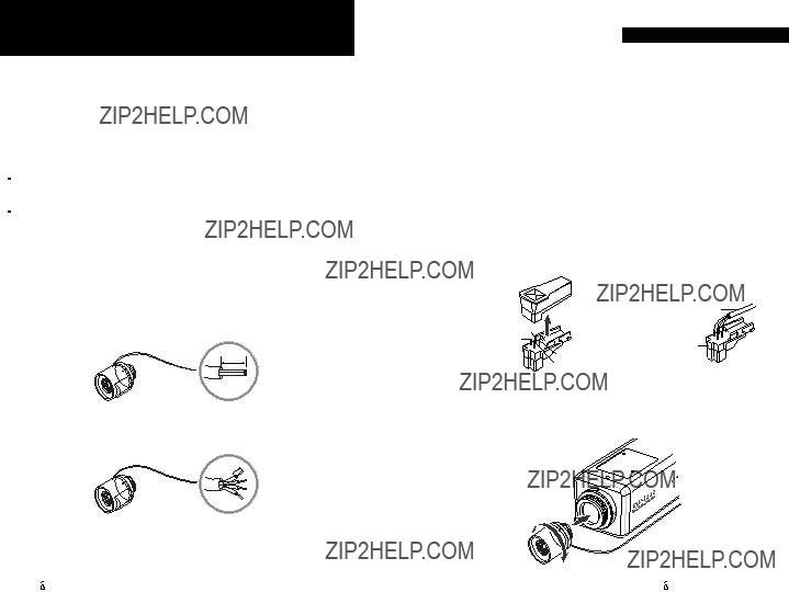
Installing Auto Iris Lens
1. Peel the end of lens cable outer cover approximately 8mm. (5/16inch)
approx.
8 mm(5/16inch)
2. Peel the end of the cable inner cover approximately 2mm. (1/16inch)
approx. 2 mm(1/16inch)
CONNECTION
3.Remove the cover from the connector pin supplied, and solder the lens cable to the connector pin as shown
below.
??? Video type :
4.Remove the protecting cap, and attach the lens into the camera by turning clockwise.
CONNECTION
5.Connect the lens plug to the auto iris connector on the rear of the camera.
6.Set the IRIS Mode selection switch to Video according to the type of the lens.
CONNECTION
Installing
1. Remove the protecting cap and
Glass Protecting Cap.
2. Attach the lens into the camera by turning clockwise.
Installing
After removing the protecting cap, attach the lens into the camera by turning clockwise.
Notes:
??? Use the lens under the specification aside.
??? Otherwise the lens can damage the camera or abnormal fixing may be resulted in.
??? A heavy lens may disturb the balance with the camera and possibly results in damage. Don't use more than 450g lens.
??? It is recommended to set the lens ALC mode to Av mode (Average). Pk mode can be occurred hunting.

CONNECTION
Connecting to Monitor
Connect the VIDEO out jack to the monitor video in jack.
CONNECTION
Connecting to Power
Each model has the different power source and the operation characteristics.
Make sure the power is supplied to the appropriate power terminals on the camera. Connect the power as referred on the following figures.
???As a connecting method varies according to instruments, refer to the manual supplied with the instrument.
???Connect the cable after power is turned off.
???Set the
AC24V, 60Hz :
AC24V, 50Hz :
Intermediate
VIDEO
IN OUT
VIDEO
75

IN OUT
 AC230V , 50Hz :
Notes:

Troubleshooting
If you have trouble operating your camera, refer to the following. If the guidelines do not enable you to solve the problem, contact an authorized technician.
Specifications

MEMO
DECLARATION OF CONFORMITY
Application of Council Directive(s)
Manufacturer's Name
Manufacturer's Address
European Representative Name
European Representative Address
Equipment Type/Environment
Model Name
Beginning Serial NO.
Year of Manufacture
Conformance to
89/336/EEC
SAMSUNG TECHWIN CO., LTD
SAMSUNG TECHWIN CO., LTD
42,
KYUNGNAM, KOREA,
Black & White CCD CAMERA
M1120001
2001
EN 60065
EN 55 013
EN 50
We, the undersigned, hereby declare that the equipment specified above conforms to the above Directive(s).
26 B W CCD CAMERA