USER MANUAL

4 CHANNELS NETWORK

DIGITAL VIDEO RECORDER

i

INSTRUCTION MANUAL

To obtain the best performance and ensure device function correctly, please read this instruction manual carefully and completely.

FCC Compliance

USER-INSTALLER CAUTION: YOUR AUTHORITY TO OPERATE THIS FCC

VERIFIED EQUIPMENT COULD BE VOIDED IF YOU MAKE CHANGES OR

MODIFICATIONS NOT EXPRESSLY APPROVED BY THE PARTY RESPONSIBLE

FOR COMPLIANCE TO PART 15 OF THE FCC RULES.

NOTE: THIS EQUIPMENT HAS BEEN TESTED AND FOUND TO COMPLY WITH

THE LIMITS FOR A CLASS A DIGITAL DEVICE, PURSUANT TO PART 15 OF THE

FCC RULES. THESE LIMITS ARE DESIGNED TO PROVIDE REASONABLE

PROTECTION AGAINST HARMFUL INTERFERENCE WHEN THE EQUIPMENT IS

OPERATED IN A COMMERCIAL ENVIRONMENT. THIS EQUIPMENT

GENERATES, USES, AND CAN RADIATE RADIO FREQUENCY ENERGY AND IF

NOT INSTALLED AND USED IN ACCORDANCE WITH THE INSTRUCTION

MANUAL, MAY CAUSE HARMFUL INTERFERENCE TO RADIO

COMMUNICATIONS.

OPERATION OF THIS EQUIPMENT IN A RESIDENTIAL AREA IS LIKELY TO

CAUSE HARMFUL INTERFERENCE IN WHICH CASE THE USER WILL BE

REQUIRED TO CORRECT THE INTERFERENCE AT HIS OWN EXPENSE.

THIS CLASS A DIGITAL APPARATUS MEETS ALL REQUIREMENTS OF THE

CANADIAN INTERFERENCE-CAUSING EQUIPMENT REGULATIONS.

ii

Warnings and Cautions

WARINGS

TO REDUCE THE RISK OF FIRE OR ELECTRIC SHOCK, DO NOT EXPOSE THIS PRODUCT TO

RAIN OR MISTURE.

DO NOT INSERT ANY METALLIC OBJECT THROUGH VENTILATION GRILLS.

CAUTION

Explanation of Graphical Symbols

The lightning flash with arrowhead symbol, within an equilateral triangle, is intended to alert the user to the presence of insinuated ???dangerous voltage??? within the product???s enclosure that may be of sufficient magnitude to constitute a risk of electric shock to persons.

The exclamation point within an equilateral triangle is intended to alert the user to the presence of important operating and maintenance (servicing) instruction in the literature accompanying the product.

USERS OF THE SYSTEM ARE RESPONSIBLE FOR CHECKING AND COMPLYING WITH ALL

FEDERAL, STATE, AND LOCAL LAWS AND STATUTES CONCERNING THE MONITORING AND

RECORDING OF VIDEO AND AUDIO SIGNALS. ULTRAK SHALL NOT BE HELD RESPONSIBLE

FOR THE USE OF THIS SYSTEM IN VIOLATION OF CURRENT LAWS AND STATUTES.

iii

iv

SETUP MENU List

SETUP MENU

SYSTEM SETUP

CAMERA SETUP

RECORD SETUP

SCHEDULE RECORD

EVENT LIST

HDD MANAGEMENT

LOAD DEFAULT

EXIT

MOTION EVENT MIGRATION OFF

EXIT

SCHEDULE RECORD

??

O O O O O O O O O O O O O O O O O -

PRESS [UP???DOWN] TO SELECT

PRESS [ENTER] TO SET??? [MENU] TO EXIT

v

CHAPTER 1

INTRODUCTION

This product is 4 cameras input appliance with multiple function which will bring you following features:

zDevice can be performed as VHS system with live display, play back and video recording???

zDevice operates in hardware base with no OS (operating system) necessary for more reliability and stability???

zDigitize data storage with M-JPEG compression technology will give you organized video data management without using mess huge traditional video tape???

zSupport various type of camera with real, live mode display???

zMulti-speed recording selection on normal recording mode or alarm recording mode, the highest speed of recording is 30/25 (NTSC/PAL) fields on both mode???

zContrast, hue and brightness are adjustable for each camera individually???

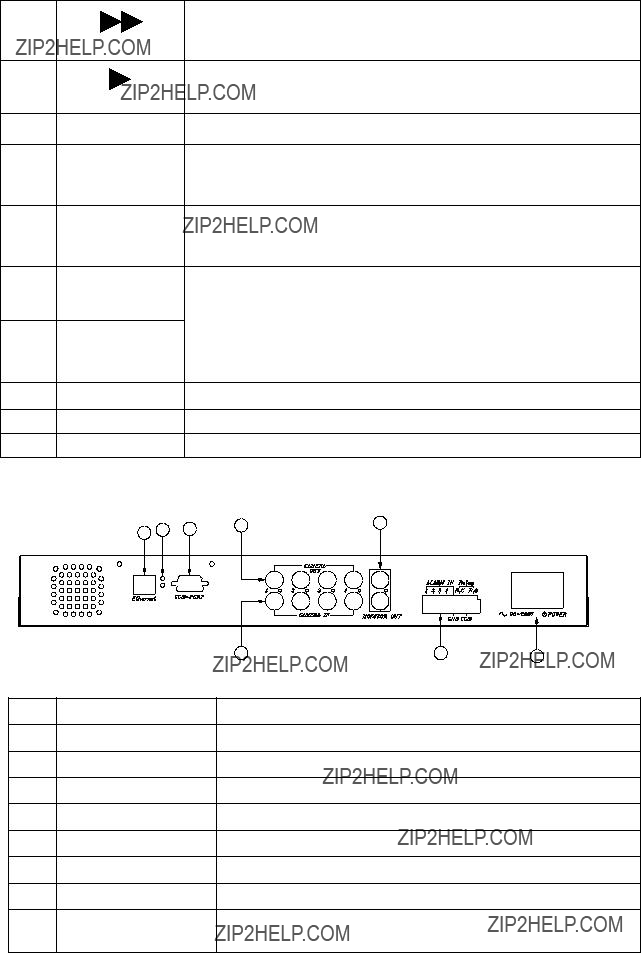
zSupport up to 2 hard disks (HDD) from 40GB to 250GB compatible???

zWhen external alarm is triggered , correspond cameras number will show up on the monitor with texts???

zSelectable recording qualities (best/high/medium/low)???

zRecording can operate manually or gets activated automatically when alarm is triggered???

zMotion detection function available, user can easily adjust sensitive of motion detection???

zPlayback record can be searched by time or by event list???

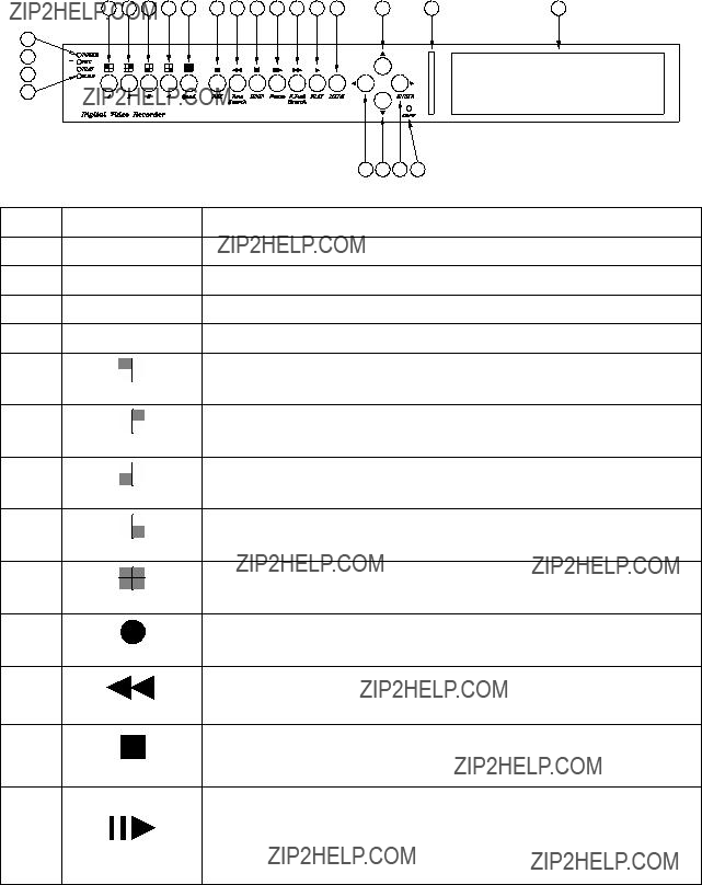
zPlay back mode could not be easier then ever for you to review the video that gets recorded on reverse (x6) and fast forwarding (??2, ??4, ??6)???

zPlay back mode with pause (field by field) for forward???

zEasy operation, setting can be easily modified OSD (on screen display) menu???

zDevice will overwrites data and notice operator on monitor when the HDD is going full???

zHDD capacity status can be display on the screen for better storage management???

zSystem will restore the previous setting and continue camera activity after restart???

zKey lock function available to secure your DVR from button pressing accidentally???

zProvide 2 Monitor output???

zOptional network function

zSupport compact flash (CF) card for random backup and VCR for fully backup???

zAlarm notification could be sent via email when motion or external alarms are triggered.

1

CHAPTER 2

Hardware Overview

Front Panel Layout Overview

1

2

3

4

2

3

iLOAD DEFAULT

eHDD PASSWARD

A password can be setup to protect the hard disk content. It needs to be entered in order to perform a hard disk format. Initial number is 1111.

Use the view control button on the front panel to input the number. is ???1??? , is ???2??? , is ???3??? , is ???4???

fSET TIME/DATE

Use the ??? or ??? button to select items.

Press the ??? or ??? button to increase / decrease the number.

gEXIT

4

Exit from the SYSTEM SETUP menu

3. CAMERA SETUP

Press the MENU button to go into the main menu.

Use the ??? or ??? button to select items.

Press the ??? or ??? button to confirm the selection.

Press MENU to escape to exit the set up mode.

Use ??? or ??? button to select ON/OFF motion detection.

4MOTION SENSITIVITY(1~10)

Use ??? or ??? button to adjust sensitivity of motion detection for selected camera. Initial number from 1 to 10, default value is 5(STANDARD).

5BRIGHTNESS STANDARD(1~10)

Use ??? or ??? button to adjust the brightness of the selected camera. Initial number is 5 (STANDARD).

6CONTRAST STANDARD(1~10)

Use ??? or ??? button to adjust the contrast of the selected camera. Initial number is 5 (STANDARD).

7HUE STANDARD(1~10)

Use ??? or ??? button to adjust the hue of the selected camera. Initial number is 5 (STANDARD).

8EXIT

Exit from the CAMERA SETUP menu

4. RECORD SETUP

Press the MENU button to go into the main menu.

Use the ??? or ??? button to select items.

Press the ??? or ??? button to confirm the selection.

Press MENU to escape to exit the set up mode.

5

detection is triggered.

Note: PAL: (1~4P/6P/8P/12P/25P) NTSC=15P, PAL=12P on default. f ALARM RECORD DWELL 5SEC (1-30)

Use ??? or ??? button to set the dwell time for alarm recording when external alarm or motion detection is triggered.

When external alarm is triggered and within the dwell period:

-the screen will be switched into 4 format.

-The corresponding camera will be marked ID ???EXT??? g RECORD QUALITY HIGH(BEST/HIGH/MEDIUM/LOW)

Use ??? or ??? button to select the BEST, HIGH, MEDIUM or LOW setting so there is a total of four levels of recording quality that can be chosen from. The higher the quality, the higher the amount of storage will be consumed. Thus, this setting should be carefully chosen as it will affect the usage of hard disk storage.

A table of relationship between quality, record speed and hard disks is attached for Reference.

hMOTION EVENT MIGRATION OFF

You can decide to include or exclude motion events by turning on or turning off in this option. The default setting is off.

iEXIT

Exit from the RECORD SETUP menu

5. SCHEDULE RECORD

Press the MENU button to go into the main menu.

Use the ??? or ??? button to select items.

Press the ??? or ??? button to confirm the selection.

Press MENU to escape to exit the set up mode.

1SCHEDULE RECORD

There are 24 circles in the schedule table, which represent 24 hours.

Every circles has 3 options to select:

O : represents ???fully record???

X : represents ???no record???

A : represents ???alarm record???

Use the ??? or ???button to select items.

Press ??? or ??? button to select the O/ X / A (Fully / No / Alarm Record).

6. EVENT LIST

Press ??? or ??? key on ???EVENT LIST??? than windows will appear as below:

Use ?????? or ?????? key to select event which needs to be played???location of ??? > ??? symbol will move up

6

and down for indicating current event which been selected.

Press ?????? or ?????? key to select events storage from master hard drive or slave hard drive . When once selection has been made and than press ???PLAY key to start playing records in normal speed. There are totally 4 different type???s event will be recorded:

1.REC???Event when start recording by press ???REC??? key.

2.PWR???System will event up from power interruption after restarting.

3.ALM???When external alarm was triggered, event up with alarm number.

4.MOT???When motion detection was triggered, event up with alarm number. Record setup ???MOTION EVENT MIGRATION??? must setting on.

7.HDD MANAGEMENT

Press the MENU button to go into the main menu.

Use the ??? or ??? button to select items.

Press the ?????? or ?????? button to confirm the selection.

Press MENU to escape to exit the set up mode.

gMASTER HDD FORMAT

Use ?????? or ?????? button to enter the MASTER HDD FORMAT menu.

PASSWORD INPUT (4) : _ _ _ _

Use the view control button on the front panel to input the number.

is ???1??? , is ???2??? , is ???3??? , is ???4???

When you key in the correct password, the screen will be displayed the following message:

PASSWORD CORRECT!

HARD DISK FORMATTED

Otherwise, the following error message will be displayed on the screen:

PASSWORD INCORRECT!

7

The slave HDD left ratio sign will be indicated in left on the screen, It can???t be revised. HDD N/A is with no HDD.

8SLAVE HDD FORMAT

Same with MASTER HDD FORMAT.

9EXIT

Escape from the HDD MANAGEMENT menu.

8. LOAD DEFAULT

Use the ?????? or ?????? button to return to the factory default. This will clear all the user settings and replace it with the original default parameters (The HDD Password and Schedule Record can???t be defaulted here).

9. EXIT

Exit from the SETUP MENU.

8

CHAPTER 4

OPERATION PROCEDURES

1Getting Started with your machine

Please assure the following instructions before you switch on the machine:

1.1Voltage check: Before power cable is connected, please check the voltage of this appliance against the supply.

Input voltage range 90~260V, frequency range 57-63Hz.

CAUTION - Damage would be caused if incorrect power voltage applied.

1.2Hard Disk connection: Make sure the 40-Pin Hard Disk Data cable and the 4-Pin power connectors are properly connected.

2 Recording

Press the REC key to enter the Recording Mode. And press the STOP key to stop recording.

z???REC[M]??? or ???REC[Q]??? sign will be indicated in top left corner on the screen, It mean you select MUX or QUAD recording.

z???15P??? sign will be indicated in top right corner on the screen, It mean the recording speed you selected. 15P means 15 fields per second.

z???O??? sign will be indicated in center corner on the screen, It mean the marked channel be recorded.

??For more information on Setting up Recording Mode, refer to Chapter 3 Record Setup

??In Recording Mode, if there is a power failure or power lost for any reasons that cause a shut down of this machine, it will be back to the Recording Mode automatically when power restored.

3 Playback

Press the ???PLAY button to into time search.

The following message will be displayed on the screen (The list of MASTER HARD DRIVE means the time it start and end be recorded at this HDD).

Press ???PLAY button to play video forward.

z???PLAY??? sign will be indicated in top left corner on the screen.

z???MUX or QUAD??? sign will be indicated in top right corner on the screen, It mean the recording mode you selected.

speed will be change circulative from ??2, ??4, to the highest ??6.

9

z ???REW??? or ???FF*2/4/6??? sign will be indicated in top left corner on the screen.

Press Pause button to pause (field by field) for forward. This function can be used in full screen and quad mode (If you choose QUAD in recording mode than it can???t playback in full screen).

z ???PAUSE??? sign will be indicated in top left corner on the screen.

Press the STOP button to leave playback mode and resume the Live Mode.

When overwrite mode is enabled with 2 hard drives, drive which is overwriting will cause recording time being divided to 2 periods as picture below:

TIME SEARCH

> MASTER HARD DRIVE 2004/JUN/13 04:12:03

RECORD SEGMENT 1

PRESS[UP,DOWN,ENTER] TO SET

PRESS[PLAY] TO PLAY,[MENU] TO EXIT

There will be 2 periods of time as RECORD SEGMENT 1 and RECORD SEGMENT 2 in master drive which means the oldest data and newest data both existing on the same hard drive. Above rules will also apply to slave hard drive.

4 Hard disk and CF Card recommend

Maximum 2 pieces and at lease one hard disk should be connect, the capacity of hard disk from 40GB to 250GB for each.

When you restart the power of this appliance after install or replace new hard disk it will be format automatically, we been tested the follow model of hard disk and recommend you use when you install by yourself.

We DO NOT suggest Samsung hard drive base on technical examination

We DO NOT suggest Hagiwara CF Card

10

BACKUP TO CF CARD PLAESE STOP ANY UNNECESSARY JOBS

5Backup

The DVR support 2 methods for backing up:

1. VCR Backup

The DVR Provides composite signal output for back-up use. You can keep the Image data, and simply just connected BNC connector, at the Back Panel of, with MONITOR OUT Connector. Press VCR REC button, after decided what recording data need to keep, during Play-Back Mode.

2. Compact Flash (CF) Card Backup

After the insertion of CF card, network function will be temporary suspended. Please press ???Refresh??? button to re-enable network function after CF card backup is done.

CF card backup is attached function of DVR network adapter; please ensure your DVR comes with network function before using CF card backup.

You will only able to make CF card backup under single channel full screen playback mode if the DVR recording in multiplexer mode.

You will only able to make CF card backup under quad playback mode if the DVR recording in quad mode.

It could be 2 file formats for CF card backup c Single picture JPEG file d Video clip AVI file It takes awhile on DVR system to be ready after CF card insertion. A CF mark will show up on middle left screen under playback mode which indicates DVR system is ready for CF backup.

c. Single picture JPEG file

Run the DVR under playback mode and switch to the channel you are going to backup (you are not allowed to perform CF card backup on single channel mode if your DVR recoding in quad mode) If you press ???COPY??? key under multiplexer recording mode with quad playback the screen will shows up PLEASE TURN TO FULL SCREEN MODE to remind you to switch to single channel mode.

Press ???PAUSE??? button then press ???COPY??? key to back a single image into JPEG file on a CF card.

The screen will first shows up CF CARD TESTING PLEASE WAIT which indicates the DVR is initializing and perform CF card testing for CF card backup and It takes around 1 second. Message will appear next in the middle of the screen and message example 23MB/121MB 81% will appear in the bottom of the screen which indicates 23M mage byte out of 121 mage byte are used and about 81% free space left in the CF card. The single image CF card backup has been done successfully when all messages are disappeared.

d. Video clip AVI file

Run the DVR under playback mode and switch to the channel you are going to backup (you are not allowed to perform CF card backup on single channel mode if your DVR recoding in quad mode) If you press ???COPY??? key under multiplexer recording mode with quad playback the screen will shows up PLEASE TURN TO FULL SCREEN MODE to remind you to switch to single channel mode.

Press ???COPY??? key to start backup a video clip images into AVI file under full screen normal speed

11

playback mode. The screen will start showing BACKUP TO CF CARD AVI FILE on top of the screen for around 1 second and then appear AVI message in the left bottom screen which is indicating DVR system is currently backing up video into buffer. Press ???COPY??? key again to terminated video backup on your ideal period, the screen will show up CF CARD PROCESSING PLEASE WAIT .. .

It takes around 1 min to save AVI file into CF card, it depend on how big the file will be.

If the backup procedure has been done successfully, the message ???CF CARD PROCESSING PLEASE WAIT ???.??? will disappear and the message SAVE OK showing up.

If the backup action is failed, screen will show SAVE FAIL PLEASE CHECK CF CARD It could be

2possibilities.

a.DVR causes internal error on buffer, please wait for 30 seconds and redo backup procedure again.

b.Improper CF card insertion or connection shortage, please unplug your CF card and put it back into CF card slot again.

Any CF card removal will trigger internal buzzer and message CF CARD REMOVED will shows up on the screen.

When insufficient capacity occurred then message WARNING CF CARD INSUFFICIENT CAPACITY will shows up, please busing your PC to free up some space on the CF card before backup.

Using CF card reader to read images backup on a CF card as procedure below: Hook up CF card USB adapter to the USB port on PC.

Follow the on CD instruction and install necessary driver files into your PC. Insert the CF card into the card reader.

6Alarm control

There are three types of alarms that the system can be configured to handle. They are 1.external alarm, 2.video lost alarm and alarm of 3.motion detection.

When 1 and 3 types of alarm were triggered, it changes recording speed as alarm recording speed. Video Lost alarm is enabled as default and cannot be changed. The buzzer will action and ???V.LOSS??? sign will be indicated on the screen.

7External alarm connector

External alarm functions only when DVR been set under recording mode. 4 input ports to receive signals from external alarm and GND port for termination. When external alarm is triggered, currents will be grounded through GND port to activate the external alarm.

a.Texts ???ALM??? will be displayed on OSD corresponding channel.

b.Relay action.

c.Recording speed will be switch from normal mode to alarm mode (refer to chapter 4 about recording setting).

d.If setting ???A??? has been set in schedule recording, will only perform recording when alarm is

12

triggered during schedule ???A??? period. Terminal connector???

Pin 1-4 ----- ALARM1-ALARM4???Camera alarm input.

8Network

Network function is optional, please ensure that you have proper DVR model for network installation. Network setup in this DVR can be done only by TCP/IP network remote computer. With network function the DVR will support remote recording and remote surveillance. Please refer to network setup manual for instructions.

SPCIFICATIONS

13

CHAPTER 5

RECORDING TIME LENGTH

Recording time length is related to recording speed and recording quality. Tables below are offered for your reference.

Record Mode=MUX

Record Mode=QUAD

Recording length under quad mode will shorter than multiplex mode and PAL will shorter than NTSC.

14

CHAPTER 6

HARD DRIVE INSTALLATION PROCEDURES

1.Hard drive jumpers need to be set properly in order to make DVR function correctly.

2.Instructions below are for second hard drive installation. If you prefer to have only one drive, please ignore instruction below. Remove DVR top cover by taking out screws from location shown below:

???

.

???

???

???

???

???

3. Below picture indicates DVR which one without a H.D.D installed.

4. Please refer to the instruction from hard drive manufactory for correct jumper setting on (master /slave) mode of the hard drive, mounting the hard drive over DVR base by facing IDE interface to DVR main board. Match screw holes from bottom to bottom of hard drive and the DVR. Turn over the DVR from top to bottom side and then mounting up the hard drive by using screws from attached accessory pack as picture below:

15

5.Hooking up IDE cable and power cable to the hard drive as picture below, please take a note on that the red line on IDE cable must be next to power cable in order to have correct instillation.

6.This DVR supports maxima 2 hard drives, please take a note on cable length that you use to hook up with the hard drive.

7.Restore top cover then hook up with power and monitor a hard drive status message will appear if it???s been installed successful.

Attentions???

1.Hard drive master and slave mode must be set correctly.

2.Primary hard drive must be set as master and slave for secondary.

3.Make sure power cable is unplugged before hard drive installation starts.

4.IDE cable and power cable must be hooking up correctly.

16