ABS Laundry
Samsung Dryer
Model DV316LG
ABS Laundry
Samsung Dryer
Model DV316LG
Notes:

CLOTHES DRYER
Model : DV316LG
Basic Model :
Model code : DV316LGW/XAA
SERVICE Manual
1. Energy Saving
2. Time Saving
3. Super Size Capacity
4. Fuzzy Algorithm
5. Easy Reversible Door

Any unauthorized use of Manual can be punished under applicable International and/or domestic law.
Samsung Electronics Co.,Ltd.
416,
Printed in Korea P/N : DC
URL : http://itself.sec.samsung.co.kr/

41#Suhfdxwlrqv
4041#Fdxwlrq#iru#vdihw|#gxulqj#vhuylflqj
1. Do not allow the customer to repair the product.
The person may be injured or the product life may be shortened..
2.Execute A/S after unplugging the power supply unit. Be careful of the electric shocks.
3.Do not plug several plugs in the same outlet.
It may cause a fire due to overheat.
4. Check for damage, pressing or burning of the power plug or outlet.
Replace it promptly if it has a problem.(It may cause the electric shocks or fire)
5. Do not clean the main body with water.
It may cause electric shocks and fire and shorten the product life)
6.The wiring of the harness shall be free from moisture and tightened during serving. It shall not be deviated by certain impact.
7.Remove any dust or filth on the housing section,wiring section,connection section during servicing. Protect from possible cause of fire such as the tracking,shortage etc.
8.Check for any marks of moisture on the electrical parts, harness section etc.
Replace the parts or remove the moisture..
9.Check the assembly status of the parts after servicing. Maintain the status before servicing..
10.Pull out the power cord by holding the plug.
Be careful of electric shocks and when the cord is damaged.
11.Unplug the power plug from the outlet when the dryer is not used. Be careful of electric shocks and fire due to the strike of lightning.
12.Do not use or store sprays or flammable materials(including gasoline,alcohol etc.) around the dryer.
Be careful of explosions or fire due to electric sparks.
13.Do not put bowls of water or wet laundry on the dryer.
If water has penetrated into the dryer, this may cause electric shocks or fire.
14. Do not install the dryer where it will be exposed to bad weather. It may cause electric shocks and fire and shorten the product life.

15.Do not push the control buttons with an awl,pin, or sharp materials. It may cause electric shocks and damage.
16.Check the wash machine is leveled horizontally and installed properly on the floor. The vibration may shorten the product life..
4051#Lpsruwdqw#Vdihw|#Lqirupdwlrq
To avoid risk of fire, electric shock, serious injury, or death when using your dryer, follow these basic precau- tions:
1.Read all instructions before using dryer.
2.Install dryer according to Installation Instructions. Refer to the Grounding Instructions in the Installation Instructions for proper grounding of the dryer.
3.Do not dry articles that have been cleaned in, washed in, soaked in, or spotted with gasoline, dry- cleaning solvents, or other flammable or explosive substances. Vapors could ignite or explode.
4.Do not use dryer to dry clothes which have traces of any flammable substance, such as vegetable oil, cooking oil, machine oil, flammable chemicals, thinner, etc., or anything containing wax or chemicals, such as mops and cleaning cloths. Flammable substances may cause fabric to catch fire by itself.
5.Do not store or use gasoline or other flammable vapors and liquids near this or any other appliance.
6.Do not allow children to play on or in dryer. Close supervision of children is necessary when dryer is used near children, a safety rule for all appliances.
7.Before dryer is removed from service or discarded, remove doors to drying compartment.
8.Do not reach into dryer if cylinder is revolving.
9.Do not install or store dryer where it will be exposed to water and/or weather.
10.Do not tamper with dryer controls.
11.Do not repair or replace any part of dryer or attempt any service, unless specifically recommended in
12.To reduce risk of electric shock or fire, do not use extension cords or adapters to connect dryer to electrical power source.
13.Use the dryer only for its intended purpose, drying clothes.
14.Always disconnect dryer from electrical supply before attempting any service. Disconnect power cord by grasping the plug, not the cord.
15.Do not use heat to dry articles containing foam rubber or similarly textured rubberlike materials.

16.Always clean the lint filter after every load. A layer of lint in the filter reduces drying efficiency and pro longs drying time.
17.Use only fabric softeners or products to eliminate static that are appropriate for automatic dryers.
18.Keep your dryer in good condition. Bumping or dropping dryer can damage safety features. If damage occurs, have dryer checked by qualified service technician.
19.Replace worn power cords and/or loose plugs.
20.Do not tumble fiberglass curtains and draperies unless the label says it can be done. If they are dried, wipe out the cylinder with a damp cloth to remove particles of fiberglass.
21.Always read and follow manufacturer??s instructions on packages of laundry aids. Heed all warnings or precautions. To reduce risk of poisoning or chemical burns, keep products away from children at all times, preferably, in a locked cabinet.
22.Never operate dryer with guards and/or panels removed.
23.Do not operate dryer with missing or broken parts.
24.Do not bypass safety devices.
25.Keep area around the exhaust opening and adjacent surrounding areas free from accumulation of
lint, dust, and dirt.
26.Interior of dryer and exhaust duct should be cleaned periodically by qualified service personnel.
27.Dryer will not operate with loading door open. DO NOT bypass door safety switch by permitting dryer to operate with door open. Dryer will stop tumbling when door is opened. Do not use dryer if it does not stop tumbling when door is opened or starts tumbling without pressing or turning the START mechanism. Remove the dryer from use and call the service person.
28.Remove laundry immediately after the dryer stops.
29.ALWAYS follow the fabric care instructions supplied by the garment manufacturer.

Hohfwulfdo#Vhuylfh#Lqirupdwlrq
Electrical Dryers
- 240 VAC, 60 Hz, 30 Amps,
Gas Dryers
- 120 VAC, 60 Hz, 15 Amps, 3??wire installa- tions
About Ground Wires
In the event of an electrical short circuit, a
ZDUQLQJ
To reduce the risk of fire, electric shock, seri- ous injury or death, all wiring and ground- ing must conform with the latest edition of the National Electric Code, or the Canadian Electrical Code, and such local regulations as might apply. It is the customer??s responsibil- ity to have the wiring and fuses checked by a qualified electrician to make sure your home has adequate electrical power to operate the dryer.
ZDUQLQJ
To avoid risk of personal injury or death due to electrical shock:
-Observe all local codes and ordinances.
-Disconnect electrical power to unit before servicing.
-Ground appliance properly.
-Check with a qualified electrician if you are not sure this appliance is properly grounded.
-DO NOT ground to gas line.
-DO NOT ground to cold water pipe if pipe is interrupted by plastic, nonmetallic gas kets, or other insulating (nonconducting) materials.
-DO NOT modify plug on power cord.
If plug does not fit electrical outlet, have proper outlet installed by qualified elec trician.
-DO NOT have a fuse in the neutral or ground circuit. A fuse in the neutral or ground circuit could result in an electrical shock.
-DO NOT use an extension cord with this appliance.
-DO NOT use an adapter plug with this appliance.
-DO NOT pinch powe cord.
ZDUQLQJ
To reduce the risk of fire and exposure to combustion gases, the dryer MUST be ex- hausted to the outdoors.
DO NOT exhaust dryer air into a window well, gas vent, chimney or enclosed, unventilated area, such as an attic, wall, ceiling, crawl space under a building or concealed space of a building.
Jdv#Gu|hu#Srzhu#Vxsso|
This equipment MUST be grounded. In the event of an electrical short circuit, grounding reduces the risk of electric shock by providing an escape wire for the electrical current. This unit is equipped with a cord having a ground- ing wire with a grounding plug. The plug must be plugged into an outlet that is properly installed and grounded.
Consult a qualified electrician or servicer if grounding instructions are not completely un- derstood, or if doubt exists as to whether the equipment is properly grounded.
Do not use an extension cord. If the prod- uct power cord is too short, have a qualified electrician install a three ?? slot receptacle. This unit should be plugged into a separate 60 hertz circuit with the electrical rating as shown on the serial plate.
Surshu#Jurxqglqj#dqg#Srodul}dwlrq#iru#453#
YrowvZdoo#Rxwohwv
For the safety of our customers and the serv- ice technician ALL gas dryers have a three!! prong power cord and MUST be connected to a properly polarized and grounded wall outlet. This information was written for those who do not understand grounding and polarization
of a wall outlet. A 120 VAC wall outlet must always be wired as shown below.
Jurxqghg
connection to the main power panel.
Jdv#Frqqhfwlrq#Lqirupdwlrq
ZDUQLQJ
To avoid death, personal injury or property damage, from fire or explosion, information in this manual must be followed exactly.
Do not store or use gasoline or other flam- mable vapors and liquids in the vicinity of this or any other appliance.
ZKDW#WR#GR#LI#\RX#VPHOO#JDV
-Do not try to light any appliance.
-Do not touch any electrical switch; do not use any phone in your building.
-Immediately call your gas supplier from a neighbor???s phone. Follow the gas suppli er???s instructions.
-If you cannot reach your gas supplier, call the fire department.
Installation and service must be performed by a qualified installer, service agency or the gas supplier.
ZDUQLQJ
To reduce the risk of fire and exposure to combustion gases, the dryer MUST be ex- hausted to the outdoors.
DO NOT exhaust dryer air into a window well, gas vent, chimney or enclosed, unventilated area, such as an attic, wall, ceiling, crawl space under a building or concealed space of a building.

4061#Suhfdxwlrqv#xsrq#Lqvwdoodwlrq
Tools needed for installation
Proper installation is the owner???s responsibility.
HOWEVER, SERVICE CALLS PERFORMED AS A RESULT OF POOR
RESPONSIBILITY OF THE INSTALLER.
Make sure you have everything necessary for proper installation.
1.GROUNDED ELECTRICAL OUTLET is required. See Electrical Requirements.
2.POWER CORD for electric dryers (except Canada).
3.GAS LINES (if a gas dryer) must meet national and local codes.
4.EXHAUST SYSTEM ??? must be rigid metal or ???exible stiffwalled metal exhaust ducting.
See Exhaust Requirements.
Control
panel
Door
Adjustable
Adjustable leg

DUCTING REQUIREMENTS
???Use a
???Do not use a smaller duct.
???Ducts larger than 4 inches (10.2 cm) in diameter can result in increased lint accumulation. Lint accumulation should be cleaned regularly.
???If a ???exible metal duct must be used, use the type with a stiff sheet metal wall. Do not use a ???exible duct with a thin foil wall. Serious blockage can result if the ???exible metal duct is bent too sharply.
???Never install any type of ???exible duct in walls, ceilings, or other concealed spaces.
???Keep exhaust duct as straight and short as possible.
???Secure joints with duct tape. Do not use screws.
???DO NOT EXHAUST DRYER INTO ANY WALL, CEILING, CRAWL SPACE, OR CONCEALED SPACE OF A
BUILDING, GAS VENT, OR ANY OTHER COMMON DUCT OR CHIMNEY.
THIS COULD CREATE A FIRE HAZARD FROM LINT EXPELLED BY THE DRYER.
???Plastic ???exible duct can kink, sag, be punctured, reduce air???ow, extend drying times, and affect dryer operation.
???Exhaust systems longer than recommended can extend drying times, affect machine operation, and may collect lint.
???The exhaust duct should end with an exhaust hood with a
???The hood should have at least 12 inches (30.5 cm) of clearance between the bottom of the hood and the ground or other obstruction. The hood opening should point down.
???Never install a screen over the exhaust outlet.
???To avoid lint buildup, do not exhaust the dryer directly into a window well. Do not exhaust under a house or porch.
???If exhaust ductwork must run through an unheated area, the duct should be insulated and slope
slightly down towards the exhaust hood to reduce condensation and lint buildup.
???Inspect and clean the interior of the exhaust system at least once a year. Unplug the power cord before cleaning.
???Check frequently to be sure the exhaust hood damper opens and closes freely.
* Do not use

If new dryer is installed into an existing exhaust system you must make sure:
???The exhaust system meets all local, state, and national codes.
???That ???exible plastic duct is not used.
???Inspect and clean all lint buildup from inside the existing duct.
???The duct is not kinked or crushed.
???The exhaust hood damper opens and closes freely.
The static pressure in any exhaust system must not exceed 0.83 inches of water column, or be less than 0. This can be measured with the dryer running with a manometer at the point where the exhaust duct connects to the dryer. A
REMOVE THE DOOR FROM ALL DISCARDED APPLIANCES TO AVOID THE DANGER OF A CHILD
SUFFOCATING.
LOCATION CONSIDERATIONS
The dryer should be located where there is enough space in front for loading the dryer, and enough space behind for the exhaust system. This dryer is
On gas dryers, adequate clearance as noted on the data plate must be maintained to ensure adequate air for combustion and proper dryer operation.
THE DRYER MUST NOT BE INSTALLED OR STORED IN AN AREA WHERE IT WILL BE EXPOSED TO
WATER AND/OR WEATHER. THE DRYER AREA IS TO BE KEPT CLEAR OF COMBUSTIBLE MATERIALS,
GASOLINE, AND OTHER FLAMMABLE VAPORS AND LIQUIDS. A DRYER PRODUCES COMBUSTIBLE
LINT. THE AREA AROUND THE DRYER SHOULD BE KEPT
ALCOVE OR CLOSET INSTALLATION
WARNING ??? The dryer must be exhausted to the outside to reduce the risk of ???re when  installed in an alcove or closet.
???No other
???WARNING: To reduce the risk of ???re, this dryer MUST BE EXHAUSTED TO THE OUTDOORS. See EXHAUST INFORMATION section.
???Minimum clearances between the dryer and adjacent walls or other surfaces are: 2??? in front, 17??? on top, 1??? on either side, and 2.375??? in the back.
???Closet front must have two unobstructed air openings for a combined minimum total area of
72 in?? with 3??? minimum clearance on the top and bottom. A louvered door with equivalent space clearance is acceptable.

MOBILE HOME INSTALLATION
The installation of the dryer in mobile homes must conform to the Manufactured Home Construction and Safety Standard Title 24 CFR, Part
When installing a dryer in a mobile home, provisions for anchoring the dryer to the ???oor must be made. Locate in an area that has adequate fresh air.
A minimum of 72 in?? (183 cm?? ) of unobstructed space is required.
All mobile home installations must be exhausted to the outside with the exhaust duct termination securely fastened to the mobile home structure, using materials that will not support combustion.
The exhaust duct may not terminate underneath the mobile home. See Exhausting section for more information.
EXHAUSTING
Exhausting the dryer to the outside will prevent large amounts of lint and moisture from being blown into the room.
In the United States:
???All dryers must be exhausted to the outside.
???Only rigid or ???exible metal duct should be used for exhausting.
In Canada:
???All dryers must be exhausted to the outside.
Outside the U.S. and Canada:
??? Refer to local codes.
 WARNING
NEVER USE PLASTIC OR
If your existing ductwork is plastic,

GAS REQUIREMENTS
Use only natural or LP (liquid propane) gases.
THE INSTALLATION MUST CONFORM WITH LOCAL CODES, OR IN THE ABSENCE OF LOCAL
CODES, WITH THE NATIONAL FUEL GAS CODE ANSI/Z223.1, LATEST REVISION (FOR THE UNITED
STATES), OR WITH THE
Gas dryers are equipped with a burner vent for use with natural gas. If you plan to use your dryer with LP (liquid propane) gas, it must be converted for safe and proper performance by a quali???ed service technician. A 1/2??? (1.27 cm) gas supply line is recommended and must be reduced to connect to the 3/8??? (1 cm) gas line on your dryer. The National Fuel Gas Code requires that an accessible, approved manual gas
Gas dryers installed in residential garages must be raised 18 inches (46 cm) above the ???oor.
Additionally, a 1/8??? (0.3 cm) N.P.T. (National Pipe Thread) plugged tapping, accessible for test gauge connection, must be installed immediately upstream of your dryer???s gas supply connection.
Your dryer must be disconnected from the gas supply pipe system during any pressure testing of the system.
DO NOT reuse old ???exible metal gas lines. Flexible gas lines must be design certi???ed by the American Gas Association (CGA in Canada).
NOTE: ??? Any pipe joint compound used must be resistant to the action of any lique???ed petroleum gas.
??? As a courtesy, most local gas utilities will inspect a gas appliance installation.
GAS IGNITION ??? Your dryer uses an automatic ignition system to ignite the burner. There is no constant burning pilot.
COMMONWEALTH OF MASSACHUSETTS INSTALLATION INSTRUCTIONS
Your dryer must be installed by a licensed plumber or gas ???tter. A ???T??? handle manual gas valve must be installed in the gas supply line to your dryer. If a ???exible gas connector is used to install your dryer, the connector must have a maximum length of 3??? (36???).
WARNING ??? Gas leaks may occur in your system, creating a dangerous situation. Gas leaks may not be detected by smell alone.
Gas suppliers recommend you purchase and install a

ELECTRICAL REQUIREMENTS
NOTE: Wiring diagram is located on plate below the control panel.
WARNING ???
???Improper connection of the equipment grounding conductor can result in a risk of electric shock. Check with a quali???ed electrician or serviceman if you are in doubt as to whether your dryer is properly grounded. Do not modify the plug provided with your dryer ??? if it doesn???t ???t the outlet, have a proper outlet installed by a quali???ed electrician.
???To prevent unnecessary risk of ???re, electrical shock, or personal injury, all wiring and grounding must be done in accordance with local codes, or in the absence of local codes, with the National Electrical Code, ANSI/NFPA No.
???All gas installations must be done in accordance with the national Fuel Code ANSI/Z2231 ??? Lastest Revision (for the U.S.) or CAN/CGA ??? B149 Installation Codes ??? Latest Revision (for Canada) and local codes and ordinances.
GROUNDING
This dryer must be grounded. In the event of malfunction or breakdown, the ground will reduce the risk of electrical shock by providing a path of least resistance for electrical current.
GAS MODELS
Your dryer has a cord with an
The plug must be plugged into an appropriate outlet that is properly installed and grounded in accordance with all local codes and ordinances.
Do not modify the plug provided with your dryer ??? if it doesn???t ???t the outlet, have a proper outlet installed by a quali???ed electrician.
NEVER CONNECT GROUND WIRE TO PLASTIC PLUMBING LINES, GAS LINES, OR HOT WATER
PIPES.
ELECTRIC MODELS
Your dryer has a cord with an
The plug must be plugged into an appropriate outlet that is properly installed and grounded in accordance with all local codes and ordinances.
If a power cord is not used and the electric dryer is to be permanently wired, the dryer must be connected to a permanent grounded metal wiring system, or an equipment grounding conductor must be run with the circuit conductors and connected to the equipment grounding terminal.

ELECTRICAL CONNE CTIONS
Before operating or testing, follow all grounding instructions in the Grounding section.
An individual branch (or separate) circuit serving only your dryer is recommended. DO NOT USE AN
EXTENSION CORD.
GAS MODELS ??? U.S. and Canada
A 120 volt, 60 Hz AC approved electrical service, with a
ELECTRIC MODELS ??? U.S. Only
Most U.S. dryers require a 120/240 volt, 60 Hz AC approved electrical service. Some require 120/208 volt, 60 Hz approved electrical service. The electric service requirements can be found on the data label located behind the door. A
???If a power cord is used, the cord should be plugged into a
???The power cord is NOT provided with U.S. electric model dryers.
IMPORTANT:
When local codes allow, the dryer electrical supply may be connected by means of a new power supply cord kit, marked for use with a dryer, that is U.L. listed and rated at a minimum of120/240 volts, 30- ampere with three No. 10 copper wire conductors terminated with closed loop terminals,
1.size of the conductors and the type of cord.
2.3/4??? (1.9 cm)
???Do not reuse a power supply cord from an old dryer. The power cord electric supply wiring must be retained at the dryer cabinet with a suitable
???Grounding through the neutral conductor is prohibited for (1) new
(2)mobile homes, (3) recreational vehicles, and (4) areas where local codes prohibit grounding through the neutral conductor. (Use
ELECTRIC MODELS ??? Canada Only
???A 120/240 volt, 60 Hz AC approved electrical service fused through a
???All Canadian models are shipped with the power cord attached. The power cord should be plugged into a
NOTE: It is not permissible to convert a dryer in Canada to 208 volts.
REPLACEMENT PARTS AND ACCESSORIES
If your dryer requires replacement parts or accessories, contact the dealer from whom you purchased your dryer or a SAMSUNG customer care center at

INSTALLATION
Parts and literature are packaged inside your dryer drum. To install:
1.Move your dryer to an appropriate location for installation. Consider installing the dryer and washer
Lay two of the carton
2.Set your dryer back in an upright position.
3.Review the Exhausting section before installing the exhaust system. Install the ductwork from your dryer to the exhaust hood. The crimped end of the duct sections must point away from your dryer.
DO NOT use sheet metal screws when assembling ducting. These joints should be taped.
Never use plastic ???exible exhaust material.
Tip for tight installations: install a section of exhaust system to your dryer before putting it in place.
Use duct tape to secure this section to your dryer, but do not cover louvers in dryer cabinet.
4. Review Electrical Requirements section.
BEFORE OPERATING OR TESTING, follow the grounding instructions in the Grounding section.
U.S. MODELS:
IMPORTANT ??? All U.S. models are produced for a
The dryer frame is grounded to the neutral conductor at the terminal block.
A
or if local codes do not permit grounding through neutral. If the
Remove the terminal block cover plate.
Insert the power cord with a
Do not loosen the nuts already installed on the terminal block. Be sure they are tight.
Use a 3/8??? (1cm) deep well socket.
5. Review Gas Requirements section. Remove the pipe thread protective cap.
Apply pipe joint compound or about 1 1/2 wraps of Te???on tape over all threaded connections.
NOTE: Pipe joint compound must be resistant to the action of any lique???ed petroleum gas.
Connect the gas supply to your dryer.
An additional ???tting is required to connect the 3/4??? (1.9 cm) female thread end of a ???exible connector to the 3/8??? (1 cm) male threaded end on the dryer.
Securely tighten the gas line ???tting over threads.
Turn on the gas supply. Check all gas connections for leaks using a soap solution.
If bubbles appear, tighten the connections and recheck.
DO NOT use an open ???ame to check for gas leaks.
1.Loosen or remove center terminal block screw.
2.Connect neutral wire (white or center wire) of the power cord to the center,
3.Connect the other wires to outer terminal block screws. Tighten screws.
4.Tighten strain relief screws.
5.Insert tab of terminal block cover into your dryer???s rear panel slot. Secure cover with
???External ground connector
??? Neutral grounding wire (green/yellow)
??? Center
??? Neutral wire (white or center wire)
??? 3/4??? (1.9 cm)
WARNING: If converting from a
1.Remove center terminal block screw.
2.Connect ground wire (green or unwrapped) of power cord to external ground conductor screw.
3.Connect neutral wire (white or center wire) of power cord and appliance ground wire (green with yellow stripes) under central screw of the terminal block.
4.Connect the other wires to outer terminal block screws. Tighten screws.
5.Tighten strain relief screws.
6.Insert tab of terminal block cover into your dryer???s rear panel slot.
Secure cover with
??? External ground connector
??? Green or bare copper wire of power cord
??? 3/4 in. (1.9 cm)
??? Center
???Grounding wire (green/yellow)
???Neutral wire (white or center wire)
6.With a level, check your dryer and make necessary adjustments to the leveling legs.
7.At this time, make sure all gas connections (on gas models), exhaust and electrical connections are complete. Plug in your dryer, and check operation by using the checklist below.
8.(GAS MODELS ONLY)
The burner may not ignite initially due to air in the gas line. Allowing your dryer to operate on a heat setting will purge the line. If the gas does not ignite within 5 minutes, turn your dryer off and wait
5 minutes. Be sure the gas supply to your dryer has been turned on. In order to con???rm gas ignition, check the exhaust for heat.
FINAL INSTALLATION CHECKLIST
???Dryer is plugged into electrical outlet and properly grounded.
???Exhaust ductwork is hooked up and joints taped.
???Plastic ???exible duct is NOT used.
???Use rigid or
???Dryer is level with all legs ???rmly on the ???oor.
???Gas models ??? gas is turned on with no gas leaks.
???Start your dryer to con???rm that it runs, heats, and shuts off.
Dryer Exhaust Tips
WARNING: Plastic or
1.Let your dryer exhaust the air easily.
2.Use 4??? diameter rigid metal duct.Tape all joints, including at the dryer. Never use
3.Keep ducts as straight as possible.
4.Clean all old ducts before installing your new dryer. Be sure vent ???ap opens and closes freely.
Inspect and clean the exhaust system annually.
Don???t let a poor exhaust system slow drying by:
1.Restricting your dryer with a poor exhaust system.
2.Using a plastic, thin foil, or
3.Using unnecessarily long duct runs with many elbows.
4.Allowing crushed or clogged ducts and vent.

Door Reversal

2. PRODUCT SPECIFICATIONS

5051#VSHFLILFDWLRQV#RI#SURGXFW

5061#RYHUYLHZ#RI#WKH#GU\HU

61#RSHUUDWLQJ#LQVWDOODWLRQV#DQG#LQVWDOODWLRQ
6041#RYHUYLHZ#RI#WKH#FRQWURO#SDQHO
1. Digital Graphic Display
The display window shows the estimated time remaining in the cycle after the Cycle Selector dial is pressed. The estimated time remaining may ???uctuate as the cycle progresses.
The Drying light will illuminate and remain lit until the cycle is complete. When your dryer is in the
When your dryer is in the wrinkle prevent phase, the Wrinkle Prevent light will illuminate.
When the cycle is complete, ???END??? will appear in the display panel until the dryer door is opened or Power key is pushed.
If your dryer is paused during a cycle, the indicator lights will blink until the Cycle Selector dial is pressed.
2. Dry Level Selection Button
To select the dry level in the Normal, Heavy Duty, or other Sensor Dry cycles, press the Dry Level button. An indicator light will illuminate next to the desired dryness level.
Press the button repeatedly to scroll through the settings. Larger or bulkier loads may require the Very Dry (select models) or More Dry setting for complete dryness.
The Less Dry setting is best suited for lightweight fabrics or for leaving some moisture in the clothing at the end of the cycle. Damp Dry (select models) is designed to partially dry items.
Use for items that lay ???at or hang to dry.
3. Temp Selection Button
To select the correct temperature for the load, press the Temp button. An indicator light will illuminate next to the desired temperature. Press the button repeatedly to scroll through the settings.
High ??? For sturdy cottons or those labeled Tumble Dry.
Medium ??? For permanent press, synthetics, lightweight cottons, or items labeled Tumble Dry Medium. Medium Low ??? For lower heat than Medium to dry synthetic or washable knit fabrics.
Low ??? For heat sensitive items labeled Tumble Dry Low or Tumble Dry Warm. Extra Low ??? Provides the lowest heated dry temperature possible.
4. Time Selection Button
When using Manual Dry cycles, time can be adjusted by pressing time selection button. During the Sensory Dry cycle, the time light indicator is off because exact drying times are determined by ???uctuating humidity levels.

5. Signal Selection Button
When the cycle is complete, a chime will sound.
When the Wrinkle Prevent option is selected, the chime will sound intermittently. Adjust the volume of the chime or turn it off by pressing the Signal button. Press the button repeatedly to scroll through the choices.
6. Wrinkle Prevent Selection Button
Wrinkle Prevent provides approximately 90 minutes of intermittent tumbling in unheated air at the end of the cycle to reduce wrinkling. Press the Wrinkle Prevent button to activate this feature. The indicator light above the pad will illuminate when Wrinkle Prevent is selected.
Chasing lights appear in the display when the Wrinkle Prevent option is selected. The load is dry, and can be removed at any time during the Wrinkle Prevent cycle.
7. Select Cycle Option
Adjust Time ??? Time can be added or subtracted from the automatically set times in the Manual Dry cycles (Time Dry, Freshen Up, Delicates, Wrinkle Release, or Air Fluff cycles).
To add or subtract time from the cycle, press the Adjust Time arrow pad up or down until the desired time is displayed.
My Cycle ??? Choose your favorite cycle including cycle, temp, dry level option, etc.
Rack Dry ??? Rack Dry is available at Time Dry cycle. Temperature will be set only to Extra Low.
8. Cycle Selector
To select a cycle, rotate the Cycle Selector dial to the desired cycle.
The indicator light by the cycle name will illuminate. The Normal, Heavy Duty, Towels, Perm Press and Delicates cycles are Sensor Dry cycles.
Sensor Dry automatically senses the moisture in the load and shuts the dryer off when the selected dryness level (very dry to damp dry) is reached.
Normal ??? Dry loads such as cotton, underwear, and linens use this cycle to get various levels of heat for drying.
Heavy Duty ??? Use this cycle to get high heat for heavy fabrics such as jeans, corduroys, or work clothes.
Towels ??? Dry loads such as bath towels.
Perm Press ??? Dry
Delicates ??? The Delicates cycle is designed to dry
Time Dry ??? Time Dry allows you to select the desired cycle time in minutes.
Turn the Cycle Selector dial to Time Dry, then press the Adjust Time up arrow to set the drying time. Press the arrow repeatedly to scroll through the time settings.
Wrinkle Release ??? The Wrinkle Release cycle will release wrinkles from items that are clean, dry, and only slightly wrinkled, such as clothes from a crowded closet, suitcase or items that have been in the dryer too long after the cycle has ended. Wrinkle Release can be used with any temperature selection.
Air Fluff ??? The Air Fluff cycle tumbles the load in room temperature air.
9. Start/Pause Selection Button
Press to pause and restart programs.
10. Power Button
Press once to turn your dryer on, press again to turn it off. If your dryer is left on for more than 10 minutes without any buttons being touched, the power automatically turns off.

6051#F\FOH#FKDUW

6061#PDLQ#IXQFWLRQ
CHILD LOCK
A function to prevent children from playing with your dryer.
SETTING/RELEASING
If you want to set or release Child Lock, press both the Time and Signal buttons at the same time for 3 seconds.
How to Set:
1.It can be set while your dryer is running.
2.Once you set the Child Lock function, no button, except for the Power button, can be controlled until you release the Child Lock function.
3.The Child Lock indicator will be lit.
Notice:
1.If the power is on again, the Child Lock function remains unchanged.
2.To release that function, follow the instructions above.
Notice:
When other buttons, except for the Power button, do not respond, check the Child Lock indicator.
MY CYCLE
Lets you activate your customized cycle that includes Dry Level, Temp, Time option, etc.
By pushing the My Cycle button, you activate the settings used during the previous My Cycle mode. (Default : Normal Cycle)
If My Cycle mode is activated, My Cycle button will be lit.
You can select all options in My Cycle mode as follows.
1.Select cycle using Cycle Selector dial.
2.After cycle selection, set each option.
Note: At this time, the option will follow as per each cycle???s default option selection.
Then you can start My Cycle by pushing the Start/Pause button in My Cycle mode. The cycle and options you select will be displayed next time you choose My Cycle.

Rack Dry
INSTALLING THE DRYING RACK
1.Open dryer door.
2.Position drying rack in tumbler, placing the rear legs in the two recessed areas of the dryer???s back wall.
3.Place the front lip of the drying rack on top of the lint ???lter.
4.Place items to be dried on the rack, leaving space between them so air can reach all surfaces.
5.Close dryer door.
6.Use the Time Dry cycle. Select time according to moisture and weight of the items. Start dryer. It may be necessary to reset the timer if a longer drying time is needed.
WARNING ??? Drying foam rubber, plastic, or rubber on a heat setting may cause damage to the item and lead to a ???re hazard.
Memo

71#DOLJQPHQW#DQG#DGMXVWPHQWV
7041#Huuru#lwhpv#dqg#Gldjqrvwlf#Frghv
1.An occurrence of an Error will make a sound of error melody for 5sec and continuously show one of the Error Displays from the following errors.

7051#WHVW#PRGH
Continuous Run Mode:
1.Press Signal + Dryness Level for 3 sec during Power On State (Normal User Mode) .
2.Once in Continuous Run Mode,
3.The previous cycle will restart during Continuous Run Mode until continuous run mode is disabled.
4.During Continuous Run Mode, press Signal + Dryness Level for 3 seconds to return to normal user mode.
De???nition of Special Test Mode:
-Dryer must be on before Service Mode can be entered.
-Press Signal and Temp Keys for 3 seconds, or until 3 beeps are heard.
-The machine will now be in Service Mode.
-Upon entry into Service Mode, the Sensor Bar Touch Data will be shown (Default Special Test Mode).
How to Enter:
-To enter Special Test Mode press Signal and Temp Keys for 3 seconds for 3 seconds or until the control beep.
(same for all Frontier models.)

De???nition of Sensor Bar Touch Data Mode:
- Dryer will display Sensor Bar data. This mode is default mode of entering service mode
How to Enter:
- While in Power off pressing Signal and Temp Keys for 3 seconds (same for all Frontier models.)
De???nition of Cycle Count Mode:
-While in Service Mode pressing the Signal key will put the dryer into the cycle count mode
-Cycle number executed will display.
How to Enter:
-To enter Special Test Mode press While in Service Mode pressing the Signal key for 3 seconds or until the control beep.
(same for all Frontier models.)

De???nition of Software Version Mode:
- While in Service Mode pressing the Temp key will put the dryer into the software version mode
How to Enter:
-To enter Special Test Mode press Temp Key until the control beep. (same for all Frontier models.)
ex) In case of ???U105???, U0 means major version ???v1??? 05 means minor version ???05???
Special Test Mode:
-While in Power Off, pressing the Dryness Level + Power keys simultaneously will put the dryer into the System Check mode
-??? t2 ??? will display.
-System Check Mode Progress
t2 mode Function Performed Start/Pause Motor(CW) Relay On ??? Heater Relay On ??? Heater Relay Off ??? Motor(CW) Relay Off (Circulation)

81#DVVHPEO\#DQG#GLVDVVHPEO\
8041#WRROV#IRU#GLVDVVHPEO\#DQG#DVVHPEO\
######

Warning! To avoid risk of electrical shock, personal injury or death, disconnect the power to the washing machine.

####

####

####
Reassembly procedures are in the reverse order of dissasembly procedures.

91#WURXEOH#VKRRWLQJ
9041#WURXEOH#GLDJQRVLV
-As the micom dry machine is con???gured of the complicate structure, there might be the service call.
Below information is prepared for exact trouble diagnosis and suitable repair guide.
Caution for the Repair and Replacement
Please follow below instruction for the trouble diagnosis and parts replacement.
1)As some electronic components are damaged by the charged static electricity from the resin
part of wash machine or the human body, prepare the human body earth or remove the potential differ ence of the human body and wash machine by contacting the power supply plug when the work contact ing to PCB is executed.
2)Since AC220~240V is applied to the triac T1 and T2 on P.C.B, the electric shock may occur by touching and be careful that the strong and weak electricity are mixed.
3)As the P.C.B assembly is designed for no trouble, do not replace the P.C.B assembly by the wrong diagnosis and follow the procedure of the trouble diagnosis when the micom is not op erated normally.

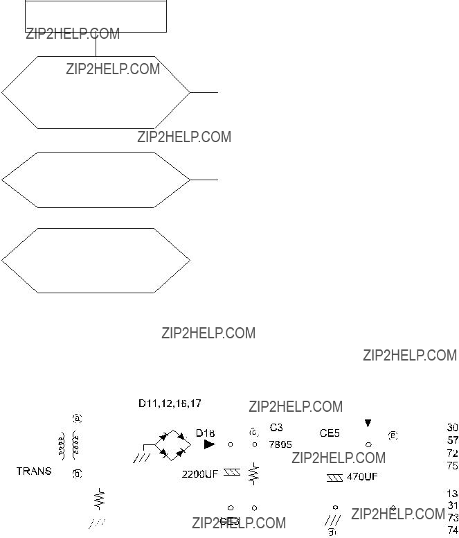
9051#SUREOHP#FKHFNLQJ#DQG#PHWKRG#RI#SFE
90504#Wkh#Sduw#Ri#Srzhu#Vrxufh#
No Power ON
905051#Uhvhw#Sduw
Yes
Check IC4
25
CE7 1UF
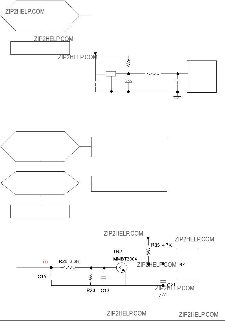
905061#Lqwhuuxsw#Sduw
Check The Curve
Output Of ??? ?
Yes
Check The Micom
Number 67 ?
Yes
Check The Part Of
Oscillator
Check D11,12,16,17,18
Check TR2,R35

905071#Fkhfnlqj#Wkh#Sduw#Ri#Dq#Rvfloodwru
Yes
Check IC4
905081#Fkhfn#Wkh#Sduw#Ri#Ex}}hu
Yes
Exchange BUZZER1,
Check R5,R46

Memo

Exploded View of Whole Parts
- 4 -

1. Exploded View of Duct, Heater, Motor
18
39
15
1
10
20
19
( GAS MODEL ONLY )
4
 21 7 31
6
27
35
17
26 5
8 35
9
25 20
48
16
- 5 -

1. Parts List of Duct, Heater, Motor
- 6 -
1. Parts List of Duct, Heater, Motor
- 7 -

2. Exploded View of Front
16
17
9
8
18
4
3
- 8 -

2. Parts List of Front
- 9 -

3. Exploded View of Drum
14
26
13
2
23
6
23
4
3
23
8
- 10 -

3. Parts List of Drum
- 11 -

4. Exploded View of Frame,
19
2
6
8
- 12 -

4. Exploded View of Frame,
- 13 -

4. Parts List of Frame,
- 14 -

4. Parts List of Frame,
- 15 -

8. ELECTRICAL PARTS LIST

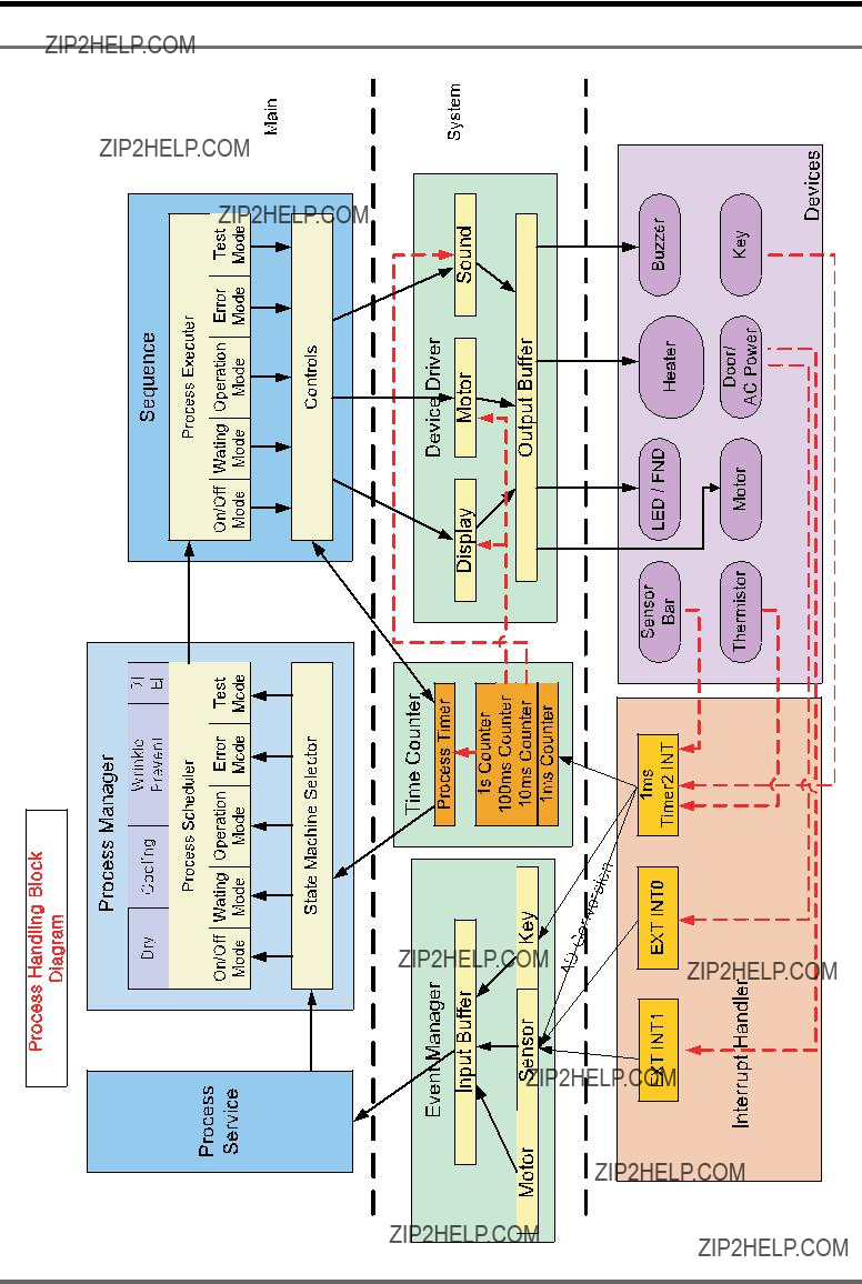
<1#EORFN#GLDJUDP

Memo

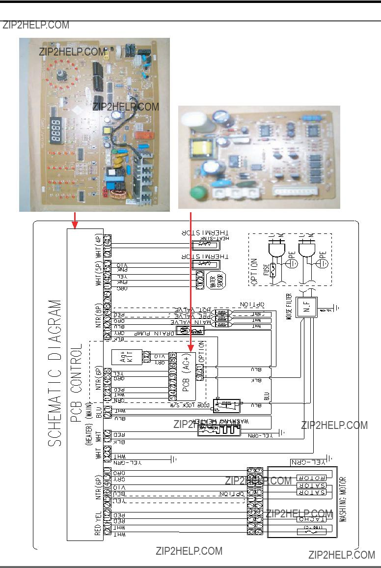
431#ZLULQJ#GLDJUDP
Memo
441#SFE#GLDJUDP
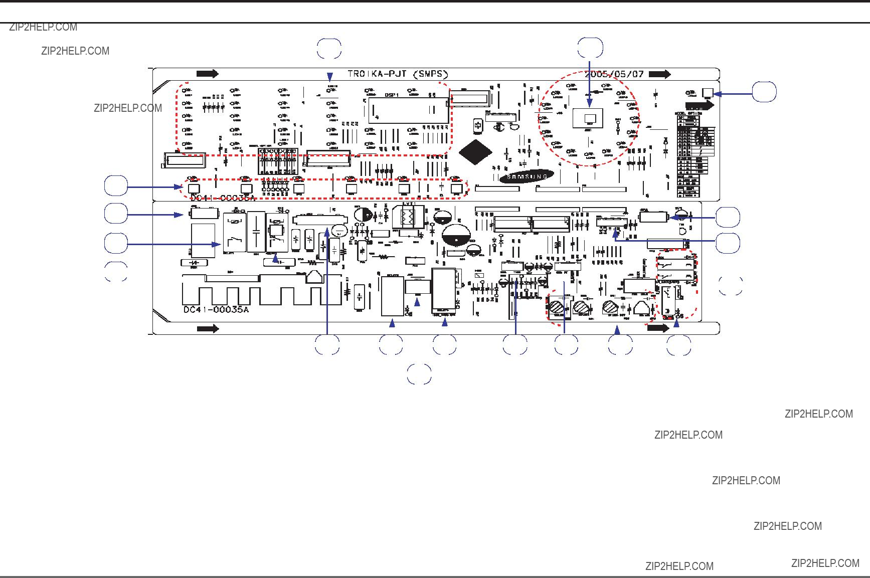
4404#PDLQ#SFE#OD\RXW
3
 7
7 


 18
18 
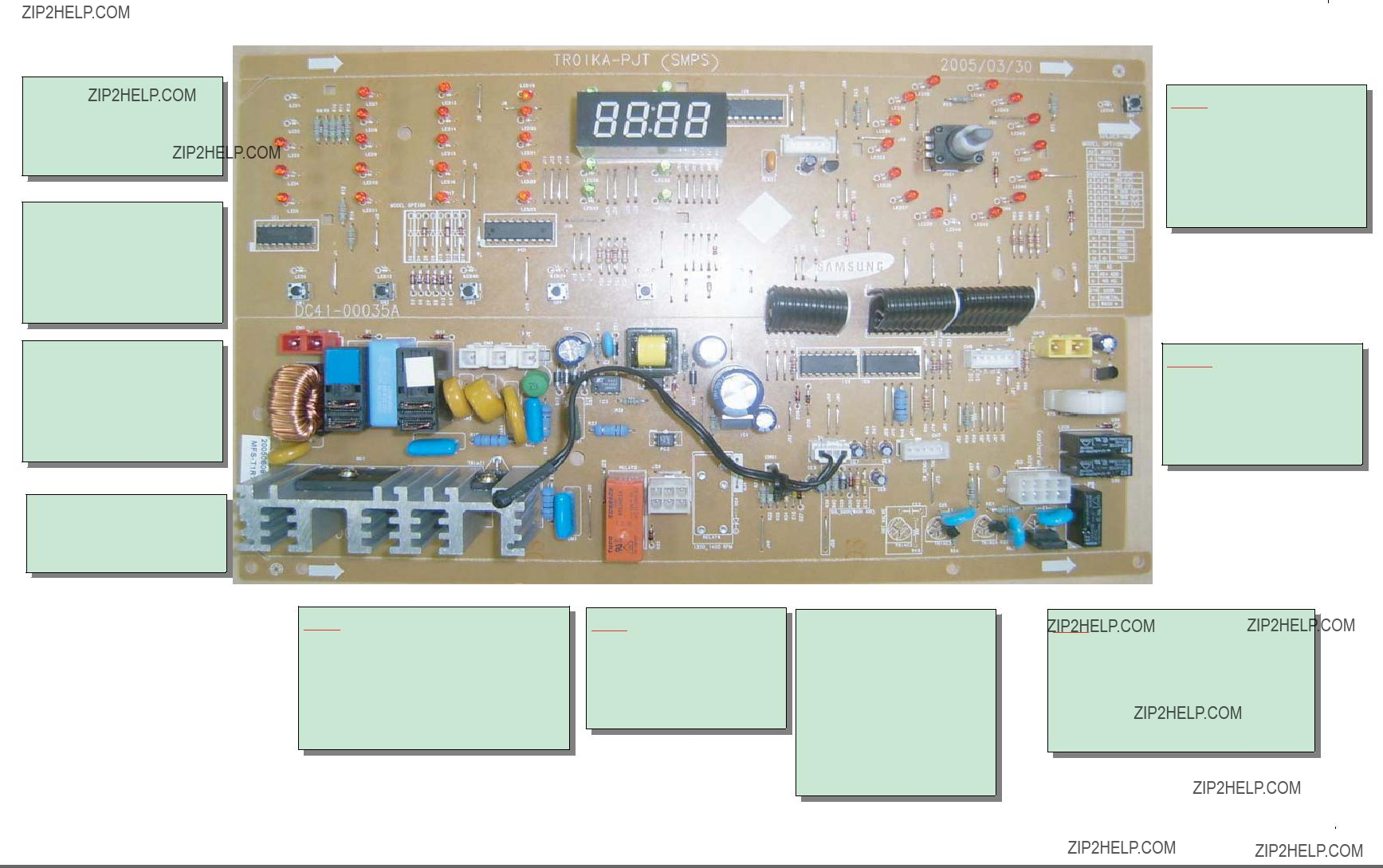
4405#Frqqhfwru#)#Uhod|#Whuplqdov#Ghvfulswlrq#+PDLQ#SFE,
????????????
???????????????????? ???? ?????? ???????????????????? ???? ?????????? ????????????
????????????
???????????????????? ???? ?????? ???????????? ???????????????????? ???? ?????? ????????????
??????
???????????????????? ???? ?????? ???????? ???????? ???????????? ???????????????????? ???? ?????? ???????? ???????? ????????????
??????
???????????????? ???? ?????? ???????????????? ???? ????????????
??????
???????????????? ???? ?????? ?????????? ???????????? ???????????????? ???? ?????? ?????????? ???????????? ???????????????? ???? ?????? ?????????? ???????????? ???????????????? ???? ?????? ?????????? ???????????? ???????????????? ???? ?????? ?????????? ????????????
??????
???????????????? ???? ?????? ???????? ????????????
???????????????? ???? ?????? ???????? ????????????
??????
???????????????? ???? ???????????? ???????????????? ???? ???? ???????????????? ???? ???? ???????????????? ???? ?????? ??????????
???????????? ???????????????? ???? ?????? ????????
????????????
??????
???????????????? ???? ?????????? ???????????????? ???? ?????????? ???????????????? ???? ???? ???????????????? ???? ?????? ???????????????? ???? ????????????
????????
???? ???????????????? ???? ?????? ?????????? ???????????? ???? ???????????????? ???? ?????? ?????????? ????????????
??????
???????????????? ???? ?????? ?????????????????????? ???????????????? ???? ?????? ???????? ?????????? ???????????????? ???? ?????? ?????? ?????????? ???????????????? ???? ?????? ?????? ?????????? ???????????????? ???? ?????? ???????? ???????? ??????

4406#Frqqhfwru#)#Uhod|#Whuplqdov#Ghvfulswlrq#+DJ0NLW#SED,
?????? ???????????????? ???? ??????
???????????????? ???? ??????
?????? ???????????????? ???? ????????????
???????????????? ???? ???? ???????????????? ???? ?????? ???????????????? ???? ???????????????? ???????????????? ???? ???????????????? ???????????????? ???? ???????? ???????????????? ???? ????????

Memo

12. SCHEMATIC DIAGRAMS
* This Document can not be used without Samsung???s authorization.
4504#PDLQ#SFE

* This Document can not be used without Samsung???s authorization.
461#FLUFXLW#GHVFULSWLRQV
46041#RYHUDOO#V\VWHP

??? Function
Generates a required DC power of 12V or 5V in case of supplied or disconnected AC power.
??? Description
-When AC 220V is applied to CN3, D17 D20 transforms it to DC 300V.
-DC 300V is generated for the LVT1 secondary source by IC3 and PC1 turning on/off.
-The secondary 12V depends on the ZD1 value.
-The 12V for the LVT1 secondary source is transformed to DC 5V through IC4

??? Function
Controls each driving system (VALVE, DOOR S/W,
??? Description
-MICOM outputs a high signal of 5V from pin # 1 - 7 of IC7 and IC9.
-Then, pin # 10 to 16 of IC7 and IC9 are electrically grounded (0V).
-When pin # 10 to 16 are grounded, this creates an electric potential difference from the 12V that turns on RELAY 5,6,7 and TRIAC2,3,4,5.
-The operating parts (VALVE,
??? Function
Supplies power to the motor and turns it CW/CCW (Right / Reverse direction).
??? Description
- The operation of TRIAC1 is the same as that of the driving system. - If the electric potential of R48 is grounded (0V), TRIAC1 turns on.
- CN1 detects if the door is locked or unlocked. If unlocked, it does not apply power to the motor even if TRIAC1 turns on.
- If the door is unlocked and TRIC turns on, the motor connected to CN4 is supplied with power and drives CW (right direction).
-Under such conditions, turning RELAY3 on will drive the motor CCW (reverse) as the wiring is switched to CCW.
-Turning RELAY4 on will switch the winding of the motor to one for higher driving.

45081#Vhqvru#Ghwhfwlrq#Flufxlw
??? Function
Detects signals from the sensor and controls the current system.
??? Description
-The water level sensor is connected to pin 4 of CN7.
-The frequency of the level sensor changes according to the water amount in the tub.
-Then, the frequency is input to MICOM pin 48 for detecting the water amount.
-The DHSEH sensor is connected to CN7 pin 5 and CN6 pins 3,4.
-The resistance of the temp. sensor changes according to the ambient temperature. The changed resistance is applied to R50 and R51.
-The voltage applied to R50 and R51 is decided according the temp. MICOM stores
the value.
-When voltage is applied to MICOM pins 22 and 23, MICOM compares it to the predefined one before detecting the current temp.
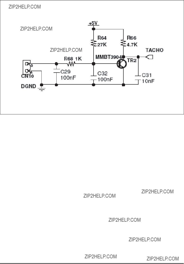
45091#Prwru#WDFKR#Lqsxw#V|vwhp
??? Function
Detects the current RPM of the motor and controls the output.
??? Description
-The motor TACHO sensor is connected to CN10
-According to the current RPM of the motor, a square wave is applied to pin 8.
-The square wave that is input to TR2 BASE turns the motor on if high (5V), and turns it off if low (0V). And this operation will be inverted to TACHO NET for a clear wave with no noise.
-The signal is applied to MICOM pin 13. Then MICOM counts the frequency of the input signal and detects the current RPM of the motor.

Memo

471#UHIHUHQFH#LQIRUPDWLRQ
47041#PRGHO#QDPH

47051#WHUPLQRORJ\
1)
???To prevent the laundry from gathering on one side of the tube causing noise and vibration, the washing machine uses an imbalance detection device that evenly disentangles the laundry before the hydrating cycle starts.
2)
???Prevents the door from being opened while a cycle is in progress. For safety purposes, it keeps the door locked even in pause mode or after the washing cycle unless the water level frequency is greater than 24.8Khz
3)
???When the water supplied is more than 2/3 of the tube capacity due to a malfunction of the water supply valve, this device automatically starts
4)THERMISTOR
???Keeps sensoring and controlling the temperature inside the tube to keep it below your settings.
5)
???When the washing heater is overheated due to an error in the thermistor or any other malfunction, the
nect the power for your and the product???s safety.
6)
???To avoid any damage to sensitive laundry, the tube temperature is detected and ???ERROR(E8)??? is displayed on the LED for Wool or Lingerie courses when the temperature is over 50 .
7)THERMOSTAT (Anti
???When the heater (drier) overheats from an error in the thermistor or any other malfunction, the thermostat (installed on the drying duct) is automatically activated to disconnect the power for your or product???s safety
8)CHILD LOCK
???Prevents children from playing with the washing machine.

<,## SUH0ZDVK
???The machine does a preliminary wash of about 10 minutes prior to the main wash. This is particularly effective for cleaning badly stained laundry.
43,##ZHLJKW#VHQVRU
???The tube automatically rotates when no water is supplied to detect the laundry weight so that the proper wash time can be determined. (Standard, Boiling, Economy Boil and Dirt courses and Toweling and Drying cycles)

47061#IDEULF#FDUH#FKDUW
Resistant material
Delicate fabric
Item may be washed at 95??C
Item may be washed at 60??C
Item may be washed at 40??C
Item may be washed at 30??C
Item may be hand washed
Dry clean only
Can be bleached in cold water
Do not bleach
Can be ironed at 200??C max
Can be ironed at 150??C max
44071#HOHFWULFDO#ZDUQLQJV
Can be ironed at 100??C max
Do not iron
Can be dry cleaned using any solvent
Dry clean with perchloride, lighter fuel, pure alcohol or R113 only
Dry clean with aviation fuel, pure alcohol or R113 only
Do not dry clean
Dry flat
Can be hung to dry
Dry on clothes hanger
Tumble dry, normal heat
Tumble dry, reduced heat
Do not tumble dry
To reduce the risk of ???re, electrical shock, and other injuries, keep these safety precautions in mind:
-Operate the appliance only from the type of power source indicated on the marking label.
If you are not sure of the type of power supplied to your home, consult your appliance dealer or local power company.
-Use only a grounded or polarized outlet. For your safety, this appliance is equipped with a polarized alter nating current line plug having one blade wider than the other.
This plug will ???t into the power outlet only one way. If you are unable to insert the plug fully into the outlet, try reversing the plug. If the plug still doesn???t ???t, contact your electrician to replace your outlet.
-Protect the power cord. Power supply cords should be routed so that they are unlikely to be walked on or pinched by items placed on or against them. Pay particular attention to cords at plugs, convenience re ceptacles, and the point where they exit from the unit.
-Do not overload the wall outlet or extension cords. Overloading can result in ???re or electric shock.

47081#T#)#D


Memo
Notes:

Be Aware, Be Alert
Always work safely.
On the Job, On the Road, In the Home
Every Time, All the Time