DESKTOP SIGN MAKER
USER'S MANUAL
ROLAND DG CORPORATION
DESKTOP SIGN MAKER
USER'S MANUAL
ROLAND DG CORPORATION

For the USA
FEDERAL COMMUNICATIONS COMMISSION
RADIO FREQUENCY INTERFERENCE
STATEMENT
This equipment has been tested and found to comply with the limits for a Class B digital device, pursuant to Part 15 of the FCC Rules.
These limits are designed to provide reasonable protection against harmful interference in a residential installation. This equipment generates, uses, and can radiate radio frequency energy and, if not installed and used in accordance with the instructions, may cause harmful interference to radio communications.
However, there is no guarantee that interference will not occur in a particular installation.
If this equipment does cause harmful interference to radio or television reception, which can be determined by turning the equipment off and on, the user is encouraged to try to correct the interference by one or more of the following measures:
-Reorient or relocate the receiving antenna.
-Increase the separation between the equipment and receiver.
-Connect the equipment into an outlet on a circuit different from that to which the receiver is connected.
-Consult the dealer or an experienced radio/TV technician for help.
Unauthorized changes or modification to this system can void the users authority to operate this equipment.
The I/O cables between this equipment and the computing device must be shielded.
For Canada
This digital apparatus does not exceed the Class B limits for radio noise emissions set out in the Radio Interference Regulations of the Canadian Department of Communica- tions.
Cet appareil num??rique ne d??passe pas les limites de la classe B au niveau des ??missions de bruits radio - ??lectriques fix??s dans le R??glement des signaux parasites par le minist??re canadien des Communications.
NOTICE
Grounding Instructions
Do not modify the plug provided - if it will not fit the outlet, have the proper outlet installed by a qualified electrician.
Check with qualified electrician or service personnel if the grounding instructions are not completely understood, or if in doubt as to whether the tool is properly grounded.
Use only
Repair or replace damaged or worn out cord immediately.
Operating Instructions
KEEP WORK AREA CLEAN. Cluttered areas and benches invites accidents.
DON???T USE IN DANGEROUS ENVIRONMENT. Don???t use power tools in damp or wet locations, or expose them to rain. Keep work area well lighted.
DISCONNECT TOOLS before servicing; when changing accessories, such as blades, bits, cutters, and like.
REDUCE THE RISK OF UNINTENTIONAL STARTING. Make sure the switch is in off position before plugging in.
USE RECOMMENDED ACCESSORIES. Consult the owner???s manual for recommended accessories. The use of improper accessories may cause risk of injury to persons.
NEVER LEAVE TOOL RUNNING UNATTENDED. TURN POWER OFF. Don???t leave tool until it comes to a complete stop.
KEEP HANDS AWAY WHEN CUTTING TOOL IS IN MOTION.
`
REGARDEZ BIEN OU VOUS METTEZ LES MAINS LORSQUE
L' OUTIL DE DECOUPE FONCTIONNE.
CAUTION
1)Unauthorized copying or transferral, in whole or in part, of this manual is prohibited.
2)The contents of this operation manual and the specifications of this product are subject to change without notice.
3)The operation manual and the product have been prepared and tested as much as possible. If you find any misprint or error, please inform us.
4)We cannot in any way assume any responsibility whatsoever with regard to whatever consequences that may happen subsequent to the making of changes or alterations to this product. We also cannot in any way assume responsibility for whatever may result when this product is operated, or with regard to whatever results from making use of any explanatory documentation.

Typographic Conventions
This manual uses certain typographic symbols, outlined below.
This indicates a point requiring particular care to ensure safe use of the product.
NOTICE
:Failure to heed this message will result in serious injury or death.
:Failure to heed this message may result in serious injury or death.
:Failure to heed this message may result in minor injury.
:Indicates important information to prevent machine breakdown or malfunction and ensure correct use.
: Indicates a handy tip or advice regarding use.
i
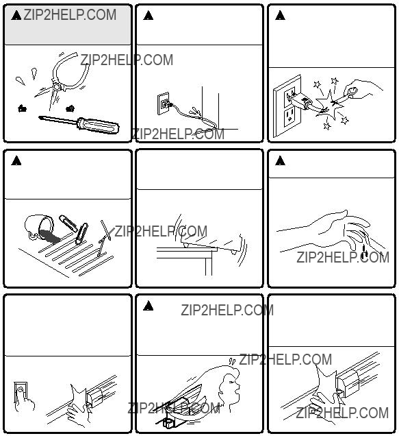
 To Ensure Safe Use
If you find some abnormality, immediately turn off the power switch and check the user's manual to find out what is wrong.
 WARNING
Never disassemble or modify this product.
 CAUTION
Do not allow liquids, metal objects or flammables inside the machine.
Fire or breakdown may result.
 CAUTION
Ensure the safety of the area around the platen before switching on the power.
The carriage moves simultaneously when the power is switched on.
ON
 CAUTION
Handle the power cord with care.
Do not step on or damage the power cord, or allow heavy objects to be placed atop it. Failure to heed this may result in electrocution or fire.
 CAUTION
Do not install in an unstable or high location.
Do not installation the machine on the edge of a table, or it may fall.
 CAUTION
Do not inadvertently allow the hands, hair, or necktie near the carriage while in operation.
 CAUTION
When pulling the power cord from an electrical socket, be sure to grip the plug.
 CAUTION
Handle the blade with care.
 CAUTION
Do not allow the hands near the platen while in operation.
ii

 About the Labels Affixed to the Unit
These labels are affixed to the body of this product. The following figure describes the location and content of these messages.
Rating plate
Do not allow the hands near the platen while in operation.
iii

To Ensure Correct Use
NOTICE
When the unit is not in use for an extended period, detach the power supply plug from the AC outlet.
3
NOTICE
Do not connect to an AC outlet that supplies other than the specified voltage.
iv

Thanks and Best Wishes
Thank you very much for purchasing the
Since we wish you many years of productive use of your
If you find some abnormality, immediately turn off the power switch and check the user's manual to find out what is wrong.
TABLE OF CONTENTS
1 PRECAUTIONS
Copyright ?? 1993 ROLAND DG CORPORATION
1

1 PRECAUTIONS
??? When Moving the
Do not try to pick up or move the
???Precautions Regarding Placement
???When choosing a place to set up the
???Since the sheet moves during cutting, make sure the unit is placed on a stable, sturdy surface. Also make sure there is nothing that can block the sheet at both front and rear.
???Never leave the unit in a place that is subject to high levels of humidity.
???Never leave the unit in a place that is subject to direct sunlight, or where the temperature could go to extremes.
???Never leave the unit in a place that is excessively dusty.
???Since it is normal for this device to emit heat when in operation, never place it where it is poorly ventilated and such heat cannot dissipate.
???Precautions in use
???To prevent injuries, be very careful when handling the blades.
???Use the rated power voltage within ??10%.
???When turning the power to the unit off and then on again, wait at least 10 seconds after switching the power off before switching it back on.
???Always be careful whenever the unit is operated so as not to risk getting fingers or hair caught in its mechanisms.
???The power cord should always be handled with due care. Do not place heavy objects upon it.
???Under no circumstances should you attempt to disassemble the unit.
???When the unit is not in use, keep the pinch rollers raised. Also, pull out the power cord plug from the receptacle.
???Never move the tool carriage by hand.
???Never allow any liquids, metallic objects, or flammable material to get inside the unit.
???Never allow any strong shock to be applied to this unit.
???Do not place heavy objects on top of the unit.
2 CHECKING SUPPLIED ITEMS
Check the following to make sure that you received all the items that were shipped along with the unit.
User's Manual: 1
2

3 PART NAMES AND FUNCTIONS
??? Front View
Stationary Pinch Roller
During cutting, this roller holds the sheet down so that it is in contact with the grit roller.
Guide Lines
Align the sheet with these lines when loading.
Grit Roller
Grasps and moves the sheet during cutting.
Platen
The sheet is moved over the platen during the cutting process.
Movable Pinch Roller
During cutting, this roller holds the sheet down so that it is in contact with the grit roller. It can easily be slid to the right or left, and should be positioned to suit the width of the sheet being used.
Tool Carriage
The tool carriage is where the blade holder is mounted. The tool carriage performs the cutting by moving the tool left/right or up/down.
DIP Switches
Used to make various settings.
Serial
Input Connector
In a serial configuration, this connector is where you need to connect the serial cable that is used to communicate with your computer.
Parallel (Centronics) Input
Connector
In a parallel configuration, this connector is where you need to connect the parallel cable that is used to communicate with your computer.
Pen Force Control Slider
Sets the blade force to be used with the tool.
Operation Panel
These are keys for making settings for the various functions.
??? Rear View
Sheet Loading Lever
Used to raise or lower the pinch rollers when loading or unloading a sheet.
Power Switch
When pushed toward [I], power is turned on.
Push toward [O] to turn it off.
Power Connector (AC IN)
This jack accepts connection of the power cord.
3
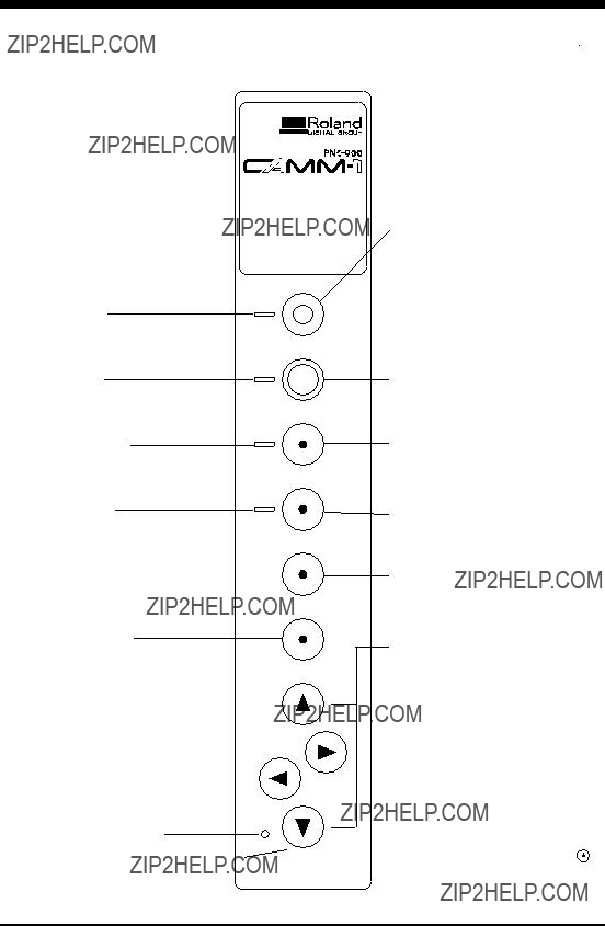
??? Operation Panel
*The TEST key and the cursor keys function only when the SETUP LED is lighted, and the ROTATE key functions only when the SETUP LED is extin- guished.
SETUP LED
This lights up when the SETUP key is pressed.
Cutting can be performed when this is lit.
PAUSE LED
This lights up when the PAUSE key is pressed to pause the
PEN MODE LED
This lights up when the PEN MODE key is pressed.
ROTATE LED
This lights up when the ROTATE key has been pressed.
ORIGIN SET Key
Press this key to move and set the origin point for cutting.
DESKTOP SIGN MAKER
SETUP
PAUSE
PEN MODE
ROTATE
TEST
ORIGIN SET
SETUP Key
After the sheet has been loaded, press this key to determine the width of the sheet automatically. Also, pressing this key after using the PAUSE key to temporarily stop a cutting operation in progress thereby deletes the data that has been sent to the
PAUSE Key
When pressed once, this temporarily halts cutting in progress. Pressing this key again releases the paused state.
PEN MODE Key
Press this to perform plotting with a pen on paper. (Be sure to load a pen in the tool carriage.)
ROTATE Key
Pressing this key sets the origin point at the bottom right of the sheet and rotates the direction of cutting by 90??.
TEST Key
Pressing this key executes a cutting test, allowing confirmation of the suitability of the pressure for the blade.


 (Cursor Keys)
Use these keys when moving the tool carriage for setting the origin or performing a cutting test.
The direction of the arrows on the  ,
,  ,
,
 , and
, and  keys indicates the direction in which the tool carriage moves in relation to
the sheet. Pressing the  key, for example, moves the tool carriage to the
left, and pressing the  key moves it to
POWER/ERROR LED
This lights up when the power is switched
POWER
the right. However, pressing the  or
or  key does not actually cause the tool carriage to move
moves. This means that pressing the
on, and flashes when an error is generated.
ERROR
causes the sheet to move toward the front
of the machine, and pressing the  key makes the sheet move to the rear.
4
4 BASIC OPERATION
*Always make sure that the power is off on both the computer and the
Power outlet
Power cord
Cables are available separately. One which you are sure matches the model of computer being used should be selected.
When the
* DIP switches settings must be made only when the power is turned off.
The DIP switches are located on the
When the
The blade offset, which is set with
The setting for sheet weight, made with
OFF
 ON
ON

 8 7 6 5 4 3 2 1
*Option required ; please consult your dealer.
???All DIP switches are set to OFF when shipped from the factory.
???When
5

*Always make sure the power switch is off before installing (or replacing) the blade. To prevent injuries, be very careful when handling the blades.
Do not touch the tip of the blade with your fingers, as the cutting performance of the blade will be impaired.
???Installation
(1)Insert the blade into the blade holder until it snaps into place with an audible click.
*Take care not to break or chip the blade.
Blade holder
Blade
Blade Completely installed
(2)Loosen the tool securing screw on the tool carriage, then insert the blade holder.
Tighten the tool securing screw until the blade holder is secured in place.
Tool carriage
Tighten
Loosen
Blade holder
Tool securing screw
4 mm
??? Removal
Tool carriage
6

???Turning on the Power
*When the power switch is pressed to turn on the unit, the tool carriage moves. Take care to ensure that your hands or other objects do not become caught in the moving parts. When turning the power to the unit off and then on again, wait at least 10 seconds after switching the power off before switching it back on.
Switch on the power switch on the left side of the
??? Loading the Sheet
Sheets with a width (horizontal dimension) of 50 mm
CAUTION
The tool carriage moves when the SETUP key is pressed. Take care to ensure that your hands or other objects do not become caught in the moving parts. Be sure to raise the sheet loading lever before attempting to move it. Never attempt to force the sheet loading lever.
(1)Move the sheet loading lever Before attempting to move the pinch roller, be sure to lower the sheet loading lever.
Sheet
Align with the guide lines
Inner side of the sheet
(2)
Raise
Sheet loading lever
When you have finished loading the sheet, be sure to set the origin to the bottom left of the sheet. See
* When using a roll sheet, load in place by passing the front edge of the sheet through from the rear of the
It may be helpful to use a sheet base (available separately).
??? Removing the Sheet
Sheet loading lever
7

About 1 mm (about 0.04")
24,998 mm
The
When the origin has been set at the desired point, cutting can be carried out anywhere on the loaded sheet.
After the sheet has been loaded, be sure to set the origin to the bottom left of the sheet. (When the Rotate function is used by pressing the ROTATE key, the direction of cutting is rotated 90??, moving the origin to the bottom right of the sheet.)
Also, to make efficient use of a sheet, you can set a new origin in an area on the sheet that has not been cut and then carry out cutting.
Immediately after loading a sheet and pressing the SETUP key to illuminate the SETUP LED, the origin point (0,0) is automatically set to a location near the stationary pinch roller.
When loading the sheet, the origin is set at the left front edge of the sheet if the sheet is loaded close to the stationary pinch roller without pulling the part of the sheet closest to the front of the unit over the platen. This makes it unnecessary to set a new origin point.
When the sheet is loaded with the part of the sheet closest to the front of the unit aligned with the guide line on the platen, no cutting is carried out on the portion of the sheet that is closer to the front of the unit than the origin point (i.e., cutting cannot be performed on areas of the sheet with negative coordinates). Follow the procedure described below to set the origin to the lower left edge of the sheet.
Procedure
* If a sheet has not yet been loaded, then before setting the origin point, refer to "Loading the Sheet" on page 7 to load the sheet correctly. Loading a sheet after the origin has been set (by pressing the SETUP key to extinguish the SETUP LED) cancels the origin that has been set.
Use the  ,
,  ,
,  , and
, and  keys to move the tool carriage to the position on the sheet where the origin point is to be set.
8
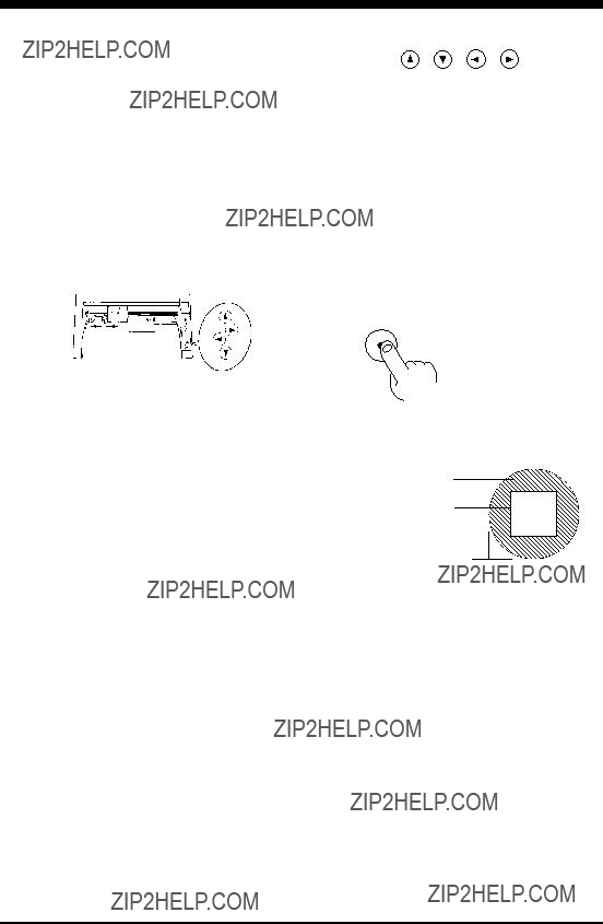
Before carrying out actual cutting, you may wish to perform a "cutting test" to check whether the unit produces the cutout satisfactorily.
This "cutting test" allows you to determine whether the settings you have for the blade force are appropriate. See below for a detailed explanation of blade force.
Procedure
*If a sheet has not yet been loaded, then refer to "Loading the Sheet" on page 7 to load the sheet correctly.
Move the pen force control slider all the way to the left (minimum blade force). Increase blade force gradually, keeping an eye on how well the sheet is being cut.
Press the TEST key
??? Cutting test starts
TEST
Use the  ,
,  ,
,  , and
, and  keys to move the tool carriage to the position on the sheet where the cutting test is to be executed.
The resulting cutouts will then appear as illustrated. When completed, first peel off the portion indicated by slanted lines. If it can be peeled off by itself, without disturbing the square, you will know that the blade force is at the appropriate level. Next, peel off the square, and look at the backing that was under it. If you can clearly make out the lines left by the blade, you will know that you have the optimum setting.
Peel off first
Then peel this off
Origin
If you do not get results like those shown above, adjust the pen force control slider to obtain the appropriate blade force.
How to Adjust Blade Force
The pen force control slider is located on the right side of the unit. Move the blade force control slider sideways to alter the blade force.
When slid to the farthest setting on the left, the blade force will be set to 30 g. As the slider is moved to the right, the blade force will be gradually increased. When at the farthest setting on the right, the blade force will be set to 200 g, which is the maximum blade force setting provided by the unit. At the center, the blade force will be approximately 120 g.
When making the blade force setting, it is important to take into consideration the hardness of the blade and the thickness of the sheet to be cut, and set the most appropriate value. If the blade force is too weak, the sheet will not be cut satisfactorily. If the blade force is too strong, blade life will be shortened.
Additionally, be aware that problems such as the following may occur.
???The sheet is easily torn
???The blade pierces the sheet
???Cutting extends through the base paper, and normal advancing of the sheet becomes impossible
???The unit suffers damage
9

The unit will begin cutting when it receives cutting data sent from the computer.
??? Software Settings
When cutting with commercially available application software, select
Select either the parallel (Centronics) or serial
*When loading a sheet that has been cut, be sure to use a sheet that is about 50 mm longer than the vertical size of the cutting data. If data larger than the vertical length of the sheet is sent, the
If the sheet becomes dislodged, immediately press the PAUSE key or turn off the power switch.
???Pausing Cutting Operations ??? PAUSE Key, PAUSE LED, and SETUP Key
If you want to stop the
Procedure
(1)
(2)
To Resume Cutting
Press the
PAUSE key
PAUSE
To Terminate Cutting
Hold down the
SETUP key
SETUP
The PAUSE LED goes out and cutting resumes
The SETUP LED goes out, cutting instructions already sent from the computer to the
* If you want to completely stop the operation of the
10

??? Continuing Cutting
Cutting After Changing the Sheet
Again carry out the procedure described from "Loading the Sheet" on page 7 to
Continuing Cutting on the Same Sheet
Refer to
??? Cutting a Thick Sheet
It is recommended that
* Remember that DIP switch settings must be made only when the power is turned off.
Once cutting has been completed, the resulting work can be affixed in place as explained below.
Procedure
Notes
???Make sure beforehand that the surface where the work is to be stuck is clean and free of all dust or oily deposits.
???When applying the work to a transparent surface, such as a window, you can use a water- based pen (which can be wiped off afterwards) to mark guidelines on the reverse side of the glass, to aid in getting the work aligned properly.
???If you discover after it is stuck in place that air bubbles were trapped under the work, use a needle to puncture them. Then you can smooth out the sheet out so that it sticks securely.
(1)
For Cut Sheets
Refer to "Removing the Sheet" on page 7 to remove the sheet from the
For Roll Sheets
Use scissors or something similar to sever the area that has been cut from the roll sheet.
(2)
Strip away all unneeded portions from the completed work.
*You should direct that a rectangle be cut around the targeted work.
11

(3)
Stick application tape over the completed work.
Press down firmly on the application sheet to remove air bubbles. If you do not press firmly enough the cut area will not stick to the surface.
(4)
Carefully apply the work at the desired location, while keeping it as straight as possible. Rub over the application tape to make sure the work is firmly stuck in place. Then peel off the application tape.
(1)When cutting is finished, press down the sheet loading levers and remove the sheet. (See "Removing the Sheet" on page 7.)
(2)If a blade was used, wipe the blade with a soft cloth to remove any pieces of the sheet that may be adhering to it. If a pen was used, remove the pen from the tool carriage and cap it securely.
(3)Turn off the power.
If you do not intend to use the unit for an extended period of time, you should pull the plug for the power cord out of the outlet.
* For routine cleaning, use a soft piece of cloth.
Performing a Demo Cutting
The
* A computer is not required in order to carry out the
(1)Refer to
(2)Set the pen force to the smallest possible value (the pen force slider should be at the furthest point to the left). If after the first test you feel that the sheet was not cutout clean enough, you can try gradually increasing the pen force until you have the optimum level.
(3)Hold down the  key on the panel while you turn the power on.
ON
POWER ON
OFF
(4)Load the sheet (or some paper), following the procedure described in
(5) Press the SETUP key. Demo cutting starts.
SETUP
12

5 SETTINGS FOR EACH FUNCTION
??? Using the Sheet Effectively
(Rotate function) ??? ROTATE Key and ROTATE LED
If there is still unused material on the right side, rotation allows you to use this remaining material effectively. This function sets the origin point at the bottom right and rotates the text (or graphics) 90??.
You have already learned of the method whereby a new user origin is set, allowing further cutting to be carried out within the remaining material. Depending on the shape and the size of characters, however, you may wish to rotate a character instead in order to cut it.
In this case, you can use the rotate function to rotate the character string "Roland" at 90??, so that the whole character string then easily fits into the available material.
Procedure
The "d" extends beyond the available material.
*If the SETUP LED is illuminated, the ROTATE LED will not light up when the ROTATE key is pressed. Press the SETUP key to extinguish the SETUP LED, then press the ROTATE key again.
(2)
(3)
Press the SETUP key
SETUP
Send cutting data from the computer
???The SETUP LED goes out
???
Character string rotated by 90??.
Canceling the Rotate Function
After holding down the SETUP key for about one second to make the SETUP LED go out, press the ROTATE key. The ROTATE LED is extinguished, and the origin returns to the point at bottom left.
The ROTATE function is also canceled when the power to the
When the character string ???Roland??? is rotated by 90 ??, the X axis, Y axis, and origin change as follows:
* The pairs of arrows indicate the positive directions along the X and Y axes.
13

??? Plotting on Paper Media ??? PEN MODE Key and PEN MODE LED
The
Since the design of the
Procedure
(1)Refer to "Installation" in on page 6 to install a pen. (In the instructions, read "pen" for "blade holder.") There is no need to perform an operation test when in the Pen Mode.
(2)Refer to "Loading the Sheet" on page 7 to load a piece of paper in the same way as for loading a sheet. Paper with a width (horizontal dimension) between 50 mm
(3)
Press the PEN MODE key
(4)Plotting begins when plotting instructions are sent from the computer.
* Be sure to perform pen plotting only in the Pen Mode.
Stopping Plotting on Paper Media
Press the PEN MODE key. The PEN MODE LED is extinguished and the unit returns to the cutting mode.
Pen Replacement
Pens will eventually wear out. Should the tip become rough and produce scratchy lines, try gradually increasing the blade force (refer to page 8,
14
6 ABOUT THE BLADE
If the blade becomes dull
When the blade starts to lose its sharpness, try gradually increasing the blade force (refer to page 8,
Increasing the blade force temporarily allows the blade to perform better. However, once the blade no longer provides reliable cutting, it is worn out. Since the blade is expendable, it must be replaced as often as necessary.
Average blade life
The life of a blade is determined mainly by the amount of cutting it performs. The following table shows the average life of blades.
The total cutting length actually obtained can vary considerably depending on the thickness, toughness, and type of adhesive layer that the sheet has. Set an appropriate blade force, one that is well matched to the type of sheet and hardness of the blade, and the life of the blade will be extended. Excessive blade forces can cause the blade to wear out quickly. Care should be taken.
15

7 WHAT TO DO IF...
If the
???Is the
???Is the unit in SETUP status (the SETUP LED is lit)?
If the SETUP LED is not illuminated, make sure the sheet is loaded correctly and press the SETUP key to illuminate the
SETUP LED.
??? Is the PAUSE LED illuminated?
If the PAUSE key has been pressed and the PAUSE LED is lit up, the unit has been paused (see "Pausing Cutting Opera- tions" on page 10).
If you want to resume cutting, press the PAUSE key again. The PAUSE LED is extinguished, and cutting resumes.
If you want to terminate cutting, first stop the transmission of cutting instructions from the computer to the
??? If connected via the serial port, do the communication parameters for the
Computer
Read the computer user???s manual and set it up correctly.
Connection cable
??? Are the computer and the
The type of cable you need is determined by your computer and the software you are using. Even if the computer is the same, running different software may require a different cable. Use the cable specified in your software.
??? Is the cable making a secure connection? Connect securely.
Software
??? Is the OS set up correctly? Check the following items:
??? Output port selection ??? Output device selection ??? Output port open ??? Communication parameters
??? Other settings
Check the OS user???s manual and set it up correctly.
??? Are the application software settings correct? Check the following items:
???Output device specifications (select a device name that matches the instruction system. If the wrong device is selected an incorrect instruction may be output, resulting in an error).
???Communication parameters
???Other settings
Check the software user???s manual and set it up correctly.
The POWER/ERROR LED is blinking
If there is an error in the data downloaded to the
??? If you are using application software, has the correct output device been selected?
Select
16

??? If you are using a program that you have created yourself, have correct commands been sent?
The
???Do the DIP switch settings match the settings made for the application software? Refer to
???Does the connecting cable match the settings for the application software and the computer?
Refer to the operation manuals for your application software and computer to select and connect the appropriate cable.
The sheet is not cut properly
??? Are the blade and blade holder installed correctly and securely?
Install these so that there is no looseness (see
??? Is the blade chipped?
If it is, replace it with a new one (see
???Check if there are any dirty deposits on the blade. If dirty, remove and clean the blade.
???Make sure you are using an appropriate blade force setting.
Perform a "cutting test," then adjust the blade force slider as necessary to obtain the optimum blade force (refer to page 9, "4- 6 Cut Test to Check Blade Force").
??? If you are cutting a thick sheet, set DIP switch
The sheet slips away from the pinch rollers during the cutting process
??? Are the sheet loading levers on both the left and right sides raised?
If a sheet loading lever has not been raised, then the sheet has not been secured in place. Make sure that the pinch rollers on the left and right sides are within the boundaries of the sheet, and raise the sheet loading levers. (Refer to
??? Make sure the sheet is parallel with the grit roller.
If the front edge of the sheet you are working with is at an angle, cut off the
??? If the sheet is to be advanced over a long distance, moving the movable pinch roller inward slightly can help prevent the
sheet from becoming dislodged. Also, after loading the sheet, it is recommended that you carry out cutting after first using the  key to advance the sheet by the amount that will be used for cutting, and make sure that the sheet does not slip away from the stationary and pinch rollers.
???If a roll sheet is used, carry out cutting after first pulling out the amount of sheet that is to be used. The sheet is susceptible to slips when it is pulled out by the cutting process.
???Make sure that the left and right edges of the sheet do not touch the inner surfaces of the
17

8 LIST OF
??? mode1
??? mode2
18

??? Instructions in mode1 and mode2
19

9 LIST OF DEVICE CONTROL INSTRUCTIONS
Device control instructions are used to determine the communication sequence between the
Each device control instruction is organized with three letters: [ESC] , "." and one uppercase letter. Device control instruc-
tions are of two types: one with parameters and the other without parameters.
Parameters can be omitted. A semicolon ";" is used as a delimiter to separate parameters if they are input in succession. A ";" without parameters means that parameters were omitted.
If parameters are omitted, the default value is set. For a device control instruction with
20

21

10 LIST OF OPTIONS
22

11 SPECIFICATIONS OF
23

??? Interface Specifications
Parallel Connector (in compliance with specifications of Centronics)
Serial Connector
24
A3020195BE