AFRICA
EGYPT
Al Fanny Trading Office
9, EBN Hagar A1 Askalany
Street,
ARD E1 Golf, Heliopolis,
Cairo 11341, EGYPT
TEL: 20-2-417-1828
REUNION
Maison FO - YAM Marcel
25 Rue Jules Hermann,
Chaudron - BP79 97 491
Ste Clotilde Cedex,
REUNION ISLAND
TEL: (0262) 218-429
SOUTH AFRICA
T.O.M.S. Sound & Music (Pty)Ltd.
2 ASTRON ROAD DENVER JOHANNESBURG ZA 2195,
SOUTH AFRICA
TEL: (011)417 3400
FAX: (011)417 3462
Paul Bothner(PTY)Ltd.
Royal Cape Park, Unit 24
Londonderry Road, Ottery 7800
Cape Town, SOUTH AFRICA
TEL: (021) 799 4900
ASIA
CHINA
Roland Shanghai Electronics
Co.,Ltd.
5F. No.1500 Pingliang Road
Shanghai 200090, CHINA
TEL: (021) 5580-0800
Roland Shanghai Electronics
Co.,Ltd.
(BEIJING OFFICE)
10F. No.18 3 Section Anhuaxili
Chaoyang District Beijing
100011 CHINA
TEL: (010) 6426-5050
HONG KONG
Tom Lee Music Co., Ltd.
Service Division
22-32 Pun Shan Street, Tsuen
Wan, New Territories,
HONG KONG
TEL: 2415 0911
Parsons Music Ltd.
8th Floor, Railway Plaza, 39 Chatham Road South, T.S.T, Kowloon, HONG KONG TEL: 2333 1863
INDIA
Rivera Digitec (India) Pvt. Ltd.
409, Nirman Kendra
Mahalaxmi Flats Compound
Off. Dr. Edwin Moses Road,
Mumbai-400011, INDIA
TEL: (022) 2493 9051
INDONESIA
PT Citra IntiRama
J1. Cideng Timur No. 15J-150
Jakarta Pusat
INDONESIA
TEL: (021) 6324170
KOREA
Cosmos Corporation
1461-9, Seocho-Dong,
Seocho Ku, Seoul, KOREA
TEL: (02) 3486-8855
MALAYSIA
Roland Asia Pacific Sdn. Bhd.
45-1, Block C2, Jalan PJU 1/39,
Dataran Prima, 47301 Petaling
Jaya, Selangor, MALAYSIA
TEL: (03) 7805-3263
PHILIPPINES
G.A. Yupangco & Co. Inc.
339 Gil J. Puyat Avenue
Makati, Metro Manila 1200,
PHILIPPINES
TEL: (02) 899 9801
SINGAPORE
SWEE LEE MUSIC
COMPANY PTE. LTD.
150 Sims Drive, SINGAPORE 387381 TEL: 6846-3676
TAIWAN
ROLAND TAIWAN
ENTERPRISE CO., LTD.
Room 5, 9fl. No. 112 Chung Shan N.Road Sec.2, Taipei, TAIWAN, R.O.C.
TEL: (02) 2561 3339
THAILAND
Theera Music Co. , Ltd.
330 Soi Verng NakornKasem,
New Road, Sumpantawongse,
Bangkok 10100, THAILAND
TEL: (02) 224-8821
AUSTRALIA/
NEW ZEALAND
AUSTRALIA/
NEW ZEALAND
Roland Corporation
Australia Pty.,Ltd.
38 Campbell Avenue
Dee Why West. NSW 2099
AUSTRALIA
For Australia
Tel: (02) 9982 8266
For New Zealand
Tel: (09) 3098 715
CENTRAL/LATIN
AMERICA
ARGENTINA
Instrumentos Musicales S.A.
Av.Santa Fe 2055
(1123) Buenos Aires
ARGENTINA
TEL: (011) 4508-2700
BARBADOS
A&B Music Supplies LTD
12 Webster Industrial Park
Wildey, St.Michael, Barbados
TEL: (246)430-1100
BRAZIL
Roland Brasil Ltda.
Rua San Jose, 780 Sala B
Parque Industrial San Jose
Cotia - Sao Paulo - SP, BRAZIL
TEL: (011) 4615 5666
CHILE
Comercial Fancy II S.A.
Rut.: 96.919.420-1
Nataniel Cox #739, 4th Floor Santiago - Centro, CHILE TEL: (02) 688-9540
COLOMBIA
Centro Musical Ltda.
Cra 43 B No 25 A 41 Bododega 9
Medellin, Colombia
TEL: (574)3812529
COSTA RICA
JUAN Bansbach Instrumentos
Musicales
Ave.1. Calle 11, Apartado 10237,
San Jose, COSTA RICA TEL: 258-0211
CURACAO
Zeelandia Music Center Inc.
Orionweg 30
Curacao, Netherland Antilles
TEL:(305)5926866
DOMINICAN REPUBLIC
Instrumentos Fernando Giraldez
Calle Proyecto Central No.3
Ens.La Esperilla
Santo Domingo,
Dominican Republic
TEL:(809) 683 0305
ECUADOR
Mas Musika
Rumichaca 822 y Zaruma
Guayaquil - Ecuador
TEL:(593-4)2302364
EL SALVADOR
OMNI MUSIC
75 Avenida Norte y Final
Alameda Juan Pablo II,
Edificio No.4010 San Salvador,
EL SALVADOR
TEL: 262-0788
GUATEMALA
Casa Instrumental
Calzada Roosevelt 34-01,zona 11 Ciudad de Guatemala Guatemala
TEL:(502) 599-2888
HONDURAS
Almacen Pajaro Azul S.A. de C.V.
BO.Paz Barahona
3 Ave.11 Calle S.O
San Pedro Sula, Honduras
TEL: (504) 553-2029
MARTINIQUE
Musique & Son
Z.I.Les Mangle
97232 Le Lamantin
Martinique F.W.I.
TEL: 596 596 426860
Gigamusic SARL
10 Rte De La Folie
97200 Fort De France
Martinique F.W.I.
TEL: 596 596 715222
MEXICO
Casa Veerkamp, s.a. de c.v.
Av. Toluca No. 323, Col. Olivar de los Padres 01780 Mexico D.F. MEXICO
TEL: (55) 5668-6699
NICARAGUA
Bansbach Instrumentos
Musicales Nicaragua
Altamira D'Este Calle Principal de la Farmacia 5ta.Avenida
1 Cuadra al Lago.#503 Managua, Nicaragua TEL: (505)277-2557
PANAMA
SUPRO MUNDIAL, S.A.
Boulevard Andrews, Albrook,
Panama City, REP. DE
PANAMA
TEL: 315-0101
PARAGUAY
Distribuidora De
Instrumentos Musicales
J.E. Olear y ESQ. Manduvira
Asuncion PARAGUAY
TEL: (595) 21 492147
PERU
Audionet
Distribuciones Musicales SAC
Juan Fanning 530
Miraflores
Lima - Peru
TEL: (511) 4461388
TRINIDAD
AMR Ltd
Ground Floor
Maritime Plaza
Barataria Trinidad W.I.
TEL: (868) 638 6385
URUGUAY
Todo Musica S.A.
Francisco Acuna de Figueroa 1771
C.P.: 11.800 Montevideo, URUGUAY TEL: (02) 924-2335
VENEZUELA
Instrumentos Musicales
Allegro,C.A.
Av.las industrias edf.Guitar import
#7 zona Industrial de Turumo Caracas, Venezuela
TEL: (212) 244-1122
EUROPE
AUSTRIA
Roland Elektronische
Musikinstrumente HmbH.
Austrian Office
Eduard-Bodem-Gasse 8,
A-6020 Innsbruck, AUSTRIA
TEL: (0512) 26 44 260
BELGIUM/FRANCE/
HOLLAND/
LUXEMBOURG
Roland Central Europe N.V.
Houtstraat 3, B-2260, Oevel
(Westerlo) BELGIUM
TEL: (014) 575811
CROATIA
ART-CENTAR
Degenova 3.
HR - 10000 Zagreb
TEL: (1) 466 8493
CZECH REP.
CZECH REPUBLIC
DISTRIBUTOR s.r.o
Voct??rova 247/16
CZ - 180 00 PRAHA 8,
CZECH REP.
TEL: (2) 830 20270
DENMARK
Roland Scandinavia A/S
Nordhavnsvej 7, Postbox 880,
DK-2100 Copenhagen
DENMARK
TEL: 3916 6200
FINLAND
Roland Scandinavia As, Filial
Finland
Elannontie 5
FIN-01510 Vantaa, FINLAND
TEL: (0)9 68 24 020
GERMANY
Roland Elektronische
Musikinstrumente HmbH.
Oststrasse 96, 22844
Norderstedt, GERMANY
TEL: (040) 52 60090
GREECE/CYPRUS
STOLLAS S.A.
Music Sound Light
155, New National Road
Patras 26442, GREECE
TEL: 2610 435400
HUNGARY
Roland East Europe Ltd.
Warehouse Area ???DEPO??? Pf.83
H-2046 Torokbalint,
HUNGARY
TEL: (23) 511011
IRELAND
Roland Ireland
G2 Calmount Park, Calmount
Avenue, Dublin 12
Republic of IRELAND
TEL: (01) 4294444
ITALY
Roland Italy S. p. A.
Viale delle Industrie 8, 20020 Arese, Milano, ITALY TEL: (02) 937-78300
NORWAY
Roland Scandinavia Avd.
Kontor Norge
Lilleakerveien 2 Postboks 95
Lilleaker N-0216 Oslo
NORWAY
TEL: 2273 0074
POLAND
ROLAND POLSKA SP. Z O.O.
UL. Gibraltarska 4.
PL-03 664 Warszawa
POLAND
TEL: (022) 679 4419
PORTUGAL
Roland Iberia, S.L.
Portugal Office
Cais das Pedras, 8/9-1 Dto 4050-465, Porto, PORTUGAL TEL: 22 608 00 60
ROMANIA
FBS LINES
Piata Libertatii 1,
535500 Gheorgheni,
ROMANIA
TEL: (266) 364 609
RUSSIA
MuTek
Dorozhnaya ul.3,korp.6 117 545 Moscow, RUSSIA TEL: (095) 981-4967
SLOVAKIA
DAN Acoustic s.r.o.
Povazsk?? 18.
SK - 940 01 Nov?? Z??mky
TEL: (035) 6424 330
SPAIN
Roland Iberia, S.L.
Paseo Garc??a Faria, 33-35
08005 Barcelona SPAIN
TEL: 93 493 91 00
SWEDEN
Roland Scandinavia A/S
SWEDISH SALES OFFICE
Danvik Center 28, 2 tr. S-131 30 Nacka SWEDEN TEL: (0)8 702 00 20
SWITZERLAND
Roland (Switzerland) AG
Landstrasse 5, Postfach,
CH-4452 Itingen,
SWITZERLAND
TEL: (061) 927-8383
UKRAINE
EURHYTHMICS Ltd.
P.O.Box: 37-a.
Nedecey Str. 30
UA - 89600 Mukachevo,
UKRAINE
TEL: (03131) 414-40
UNITED KINGDOM
Roland (U.K.) Ltd.
Atlantic Close, Swansea Enterprise Park, SWANSEA SA7 9FJ,
UNITED KINGDOM
TEL: (01792) 702701
MIDDLE EAST
BAHRAIN
Moon Stores
No.16, Bab Al Bahrain Avenue,
P.O.Box 247, Manama 304,
State of BAHRAIN
TEL: 17 211 005
IRAN
MOCO INC.
No.41 Nike St., Dr.Shariyati Ave.,
Roberoye Cerahe Mirdamad
Tehran, IRAN
TEL: (021) 285-4169
ISRAEL
Halilit P. Greenspoon & Sons
Ltd.
8 Retzif Ha'aliya Hashnya St.
Tel-Aviv-Yafo ISRAEL
TEL: (03) 6823666
JORDAN
MUSIC HOUSE CO. LTD.
FREDDY FOR MUSIC
P. O. Box 922846
Amman 11192 JORDAN
TEL: (06) 5692696
KUWAIT
EASA HUSAIN AL-YOUSIFI & SONS CO.
Abdullah Salem Street,
Safat, KUWAIT
TEL: 243-6399
LEBANON
Chahine S.A.L.
Gerge Zeidan St., Chahine Bldg., Achrafieh, P.O.Box: 16- 5857
Beirut, LEBANON
TEL: (01) 20-1441
OMAN
TALENTZ CENTRE L.L.C.
Malatan House No.1
Al Noor Street, Ruwi
SULTANATE OF OMAN
TEL: 2478 3443
QATAR
Al Emadi Co. (Badie Studio &
Stores)
P.O. Box 62, Doha, QATAR
TEL: 4423-554
SAUDI ARABIA
aDawliah Universal
Electronics APL
Corniche Road, Aldossary Bldg., 1st Floor, Alkhobar,
SAUDI ARABIA
P.O.Box 2154, Alkhobar 31952
SAUDI ARABIA
TEL: (03) 898 2081
SYRIA
Technical Light & Sound
Center
Rawda, Abdul Qader Jazairi St.
Bldg. No. 21, P.O.BOX 13520,
Damascus, SYRIA
TEL: (011) 223-5384
TURKEY
ZUHAL DIS TICARET A.S.
Galip Dede Cad. No.37
Beyoglu - Istanbul / TURKEY
TEL: (0212) 249 85 10
U.A.E.
Zak Electronics & Musical
Instruments Co. L.L.C.
Zabeel Road, Al Sherooq Bldg.,
No. 14, Grand Floor, Dubai,
U.A.E.
TEL: (04) 3360715
NORTH AMERICA
CANADA
Roland Canada Ltd.
(Head Office)
5480 Parkwood Way
Richmond B. C., V6V 2M4
CANADA
TEL: (604) 270 6626
Roland Canada Ltd.
(Toronto Office)
170 Admiral Boulevard
Mississauga On L5T 2N6
CANADA
TEL: (905) 362 9707
U. S. A.
Roland Corporation U.S.
5100 S. Eastern Avenue
Los Angeles, CA 90040-2938,
U. S. A.
TEL: (323) 890 3700

 symbol alerts the user to important instructions or warnings.The specific meaning of the symbol is determined by the design contained within the triangle. In the case of the symbol at left, it is used for general cautions, warnings, or alerts to danger.
 symbol alerts the user to items that must never be carried out (are forbidden). The specific thing that must not be done is indicated by the design contained within the circle. In the case of the symbol at left, it means that the unit must never be disassembled.

 IMPORTANT NOTES
 Table of Contents

 Introduction
 ] [
] [  ]
] ] [
] [  ]
] ], then press and hold VALUE [
  ].
]. ], then press and hold [
  ].
].


 ] and [
  ] pedals are held down simultaneously.
 To the Power Outlet

 Turn on the power of RRC2 IN device.
 Connect the RRC2 cable.

 ] and [
  ] pedals
 ] and [
  ]
] 
 Standard Mode
 ] and [
  ] pedals and the number pedals (1/6 ??? 5/10) transmits the Program Change messages and Bank select messages for the corresponding number pedals.
 ] pedal, and the numbers decrease by five; press the [
  ] pedal, and the numbers increase by five.
 ] and
] and ] pedals. To transmit Program Change messages just by pressing the [
  ] and [
  ] pedals, read
 ] [
] [  ] Pedals to Make the Settings???
  ] or [
  ] pedal to change patch numbers ten at a time. For more detailed information, see


 ].
]. ] [
] [  ] to display the pedal setting screens.
 ] [
] [  ] to change the value.
 Control Change Mode
 ] [
] [ ] Pedal


 ].
]. ] [
] [  ] to show the pedal setting screens.
 ] [
] [  ] to change the value.

 ] [
] [  ].
].
 ] [
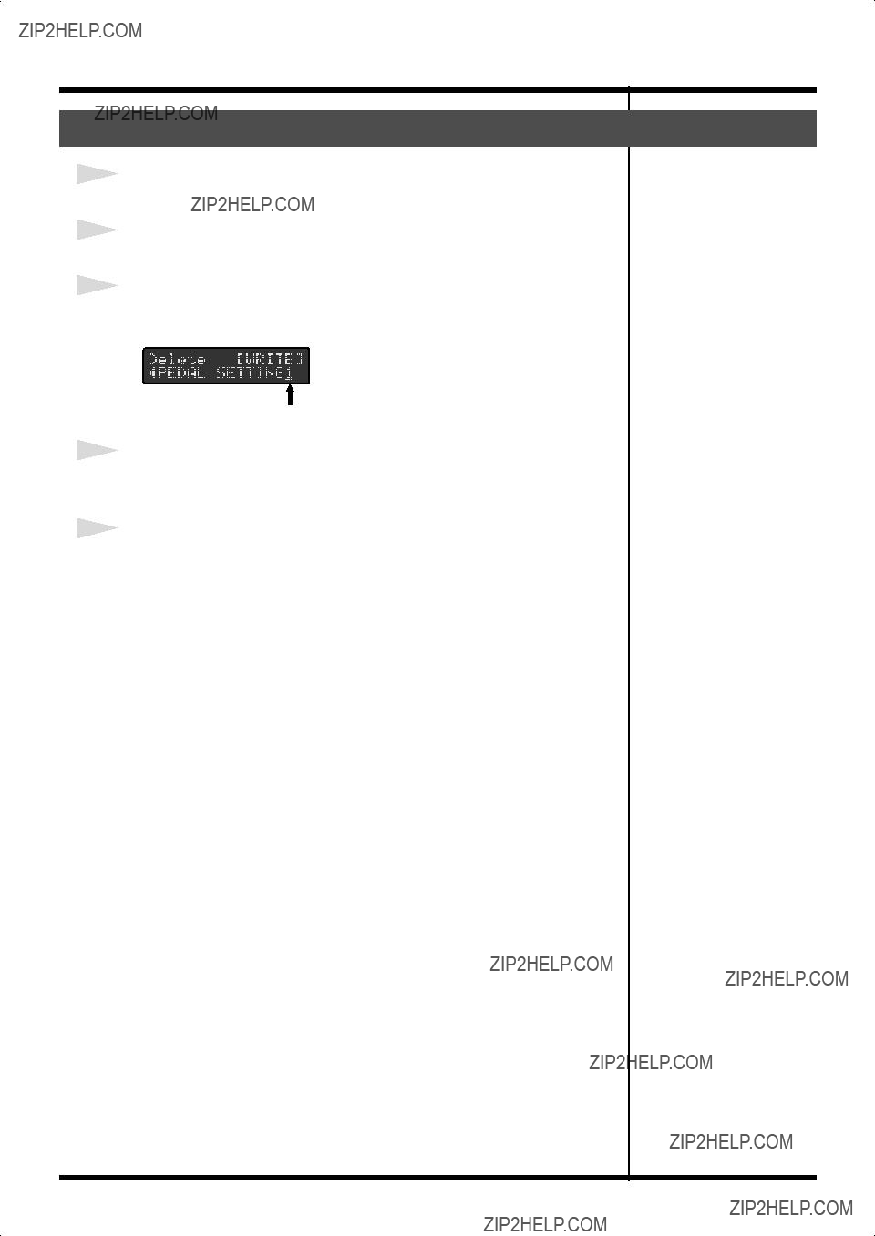
] [  ] to show the ???Delete??? screen.
 ] [
] [  ].
].
 System Exclusive Mode
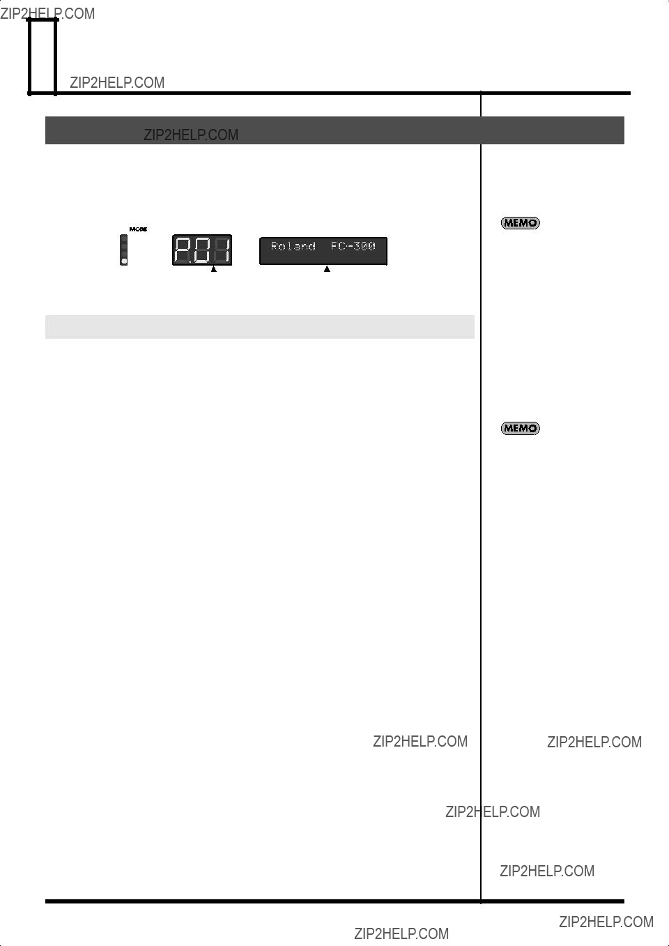
 Patch Mode

 ] and [
  ] pedals and number pedals, the MIDI messages saved to the patch are transmitted.
 ] pedal, and the numbers decrease by five; press the [
  ] pedal, and the numbers increase by five.
 ] and [
  ] pedals.
 ] and [
  ] pedals, read
 ] [
] [  ] Pedals to Make the Settings???
 ] and [
  ] pedals changes patch numbers ten at a time. For details, refer to
  ] [
] [  ] Pedal Step Size???
 ], the various pedal setting screens appear in the display. Press PARAMETER [
  ] [
] [  ] to select the parameter you want to change.
 ].
]. ] and [
  ] buttons to select the MIDI stream you want to edit, then press [WRITE].
 ] [
] [  ] then press [DEL].
 ] [
] [  ] to move the cursor to the MIDI message.
 ] [
] [  ] to move the cursor to the MIDI message.
 ] [
] [  ] to move the cursor to the data you want to change.
 ] [
] [  ] to change the value.
 ] [
] [ ] to move the cursor to the position where you want to make the addition, then press [INS]. If you want to delete a data, use PARAMETER [
  ] [
] [ ] to move the cursor to the position where you want to delete, then press [DEL].
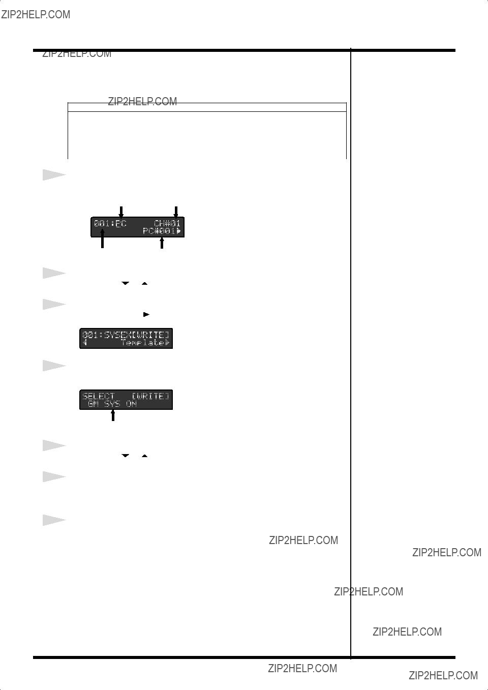
 ] [
] [  ] to move the cursor to the MIDI message.
 ] [
] [  ] to move the cursor to message number.
 ] [
] [  ] to select you want to copy (or move) message number.
 ] [
] [  ] to select the ???MOVE??? or ???COPY.???
 ] [
] [  ] to select the copy destination (or move destination) message number.
 ].
]. ] [
] [  ] to select the stream to be used as the copy source, then press [WRITE].
 ] [
] [  ] to select ???Copy MIDI,??? then press [WRITE].
 ] [
] [  ] to select the stream to be used as the copy source, then press [WRITE].
 ] [
] [  ] to select the stream to be used as the copy destination, then press [WRITE].
 ].
]. ] [
] [  ] to select the stream from which you want to delete data, then press [WRITE].
 ] [
] [  ] to select ???Delete MIDI,??? then press [WRITE].
 ].
]. ] [
] [  ] to select ???Off Timing.???
 ].
]. ] [
] [  ] to select ???AMP Ctl.???
 ].
]. ] [
] [  ] to select the each pedal settings screen.
 ] [
] [  ] to change the value.

 ].
]. ] [
] [  ] to select ???Patch Name.???
 ] to move the cursor, and press VALUE [
  ] [
] [  ] to enter the characters.
 ] [
] [  ] to select the
 ] to select ???Delete.???
 Other Features
 ] [
] [  ] to call up the parameter you want to set.
 ] [
] [  ] to set the various parameters.
 ] [
] [  ] to select ???SYS:LCD Contrast.???
 ] [
] [  ] to adjust the contrast.
 ] [
] [  ] to select ???SYS:Economy Mode.???
 ] [
] [  ] to switch Economy Mode on and off.
 ] [
] [  ] to select ???SYS:PC Mode.???
 ] [
] [  ] to make the setting.
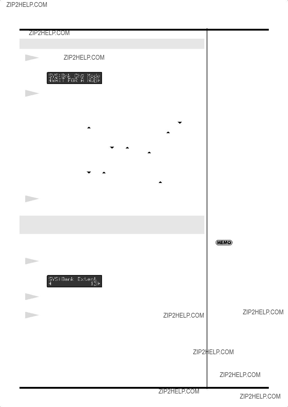
 ] [
] [  ] Pedals to Make the Settings
 ] [
] [  ] to select ???SYS:Bnk Chg Mode.???
 ] [
] [  ] to program the settings.
 ] [
] [  ] to select ???SYS:Bank Extent.???
 ] [
] [  ] to set the upper limit on the banks.
 ] [
] [  ] Pedal Step Size
 ] [
] [  ] pedals are pressed.
 ] [
] [  ] to select ???SYS:Bank Step.???
 ] [
] [  ] to make the setting.
 ] [
] [  ] to select ???SYS:Bank Display.???
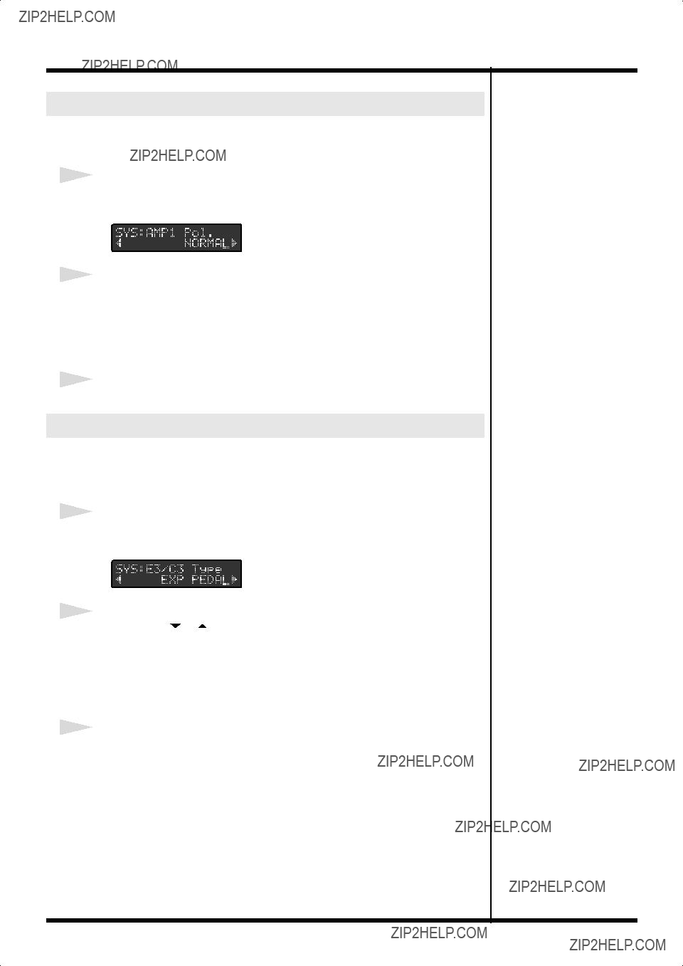
 ] [
] [  ] to select ???SYS:AMP 1 Pol.??? or ???SYS:AMP 2 Pol.???
 ] [
] [  ] to make the setting.
 ] [
] [  ] to select ???SYS:E3/C3 Type???, ???SYS:E4/C5 Type??? or ???SYS:E5/C7 Type.???
 ] [
] [  ] to select ???SYS:MODE Pdl Seq.???
 ] [
] [  ] to select ???SYS:Pdl Indicate.???
 ] [
] [  ] to make the setting.
 ] and [
  ] pedals also conform to this setting.
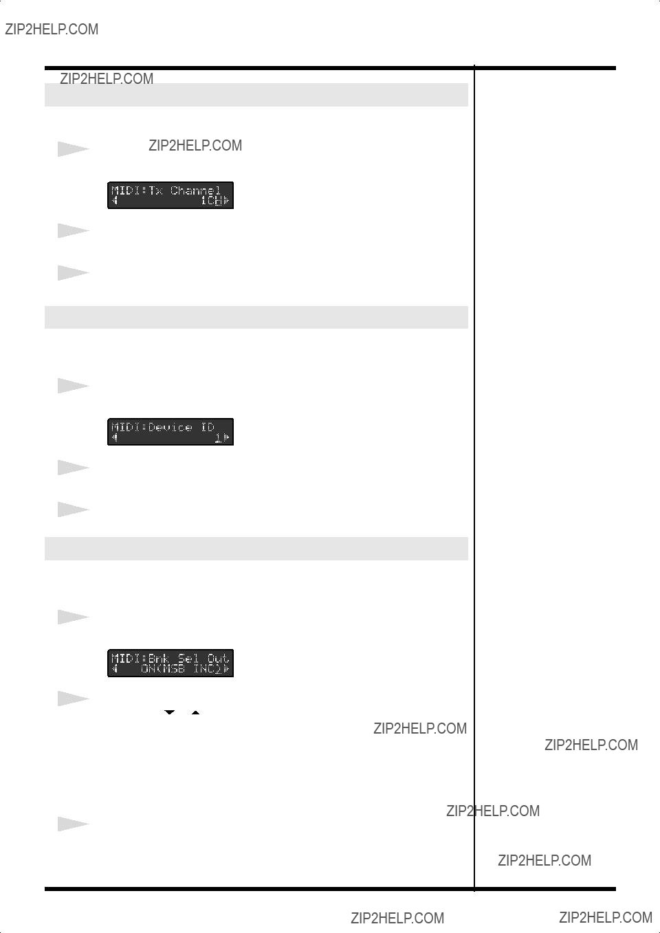
 ] [
] [  ] to select ???MIDI:Tx Channel.???
 ] [
] [  ] to set the transmit channel.
 ] [
] [  ] to select ???MIDI:Device ID.???
 ] [
] [  ] to set the Device ID.
 ] [
] [  ] to select ???MIDI:Bnk Sel Out.???
 ] [
] [  ] pedals are added to the base values set here and then output. For details, refer to
  ] [
] [  ] to select ???MIDI:Bank Select.???
 ] [
] [  ] to select either ???MSB??? or ???LSB.???
 ] [
] [  ] to make the setting.
 ] [
] [  ] to select ???Bulk Dump.???
 ] [
] [  ] to make the setting.
 ] [
] [  ] to select ???Bulk Load.???
 Appendices
 ] [
] [  ] and switch on the power.
 ] [
] [  ], and then press [WRITE].
 ] [
] [  ], and then press [WRITE].


 Request Data


 Specifications
 Index
Index
