3. Parameter address map
(Model ID = 00H 0AH)
This map indicates address, size, Data (range), Parameter, and Description of parameters which can be transferred using ???Data set 1 (DT1)???.
All the numbers of address, size, Data, and Default Value are indicated in 7-bit Hexadecimal-form.
Addresses marked at ???#??? cannot be used as starting addresses.
??? Parameter Address Block
TD-10 (Model ID = 00H 0AH)
+?????????????????????????????????????????????????????????????????????????????????????????????????????????????????????????????????????????????????????????????????????????????????????????????????????????????????????+
|???????????????????????????????????????+???????????????????????????????????????????????????????????????????????????????????????????????????????????????????????????????????????????????????????????????????????????| | 00 00 00 00 | SETUP(Individual) *1-1| |???????????????????????????????????????+???????????????????????????????????????????????????????????????????????????????????????????????????????????????????????????????????????????????????????????????????????????|
|???????????????????????????????????????+???????????????????????????????????????????????????????????????????????????????????????????????????????????????????????????????????????????????????????????????????????????|
|???????????????????????????????????????+???????????????????????????????????????????????????????????????????????????????????????????????????????????????????????????????????????????????????????????????????????????| | 10 00 00 00 | PATTERN(Bulk)*1-4| |???????????????????????????????????????+???????????????????????????????????????????????????????????????????????????????????????????????????????????????????????????????????????????????????????????????????????????| | 40 00 00 00 | SETUP(Bulk)*1-1| |???????????????????????????????????????+???????????????????????????????????????????????????????????????????????????????????????????????????????????????????????????????????????????????????????????????????????????|
|???????????????????????????????????????+???????????????????????????????????????????????????????????????????????????????????????????????????????????????????????????????????????????????????????????????????????????|
+?????????????????????????????????????????????????????????????????????????????????????????????????????????????????????????????????????????????????????????????????????????????????????????????????????????????????????+
* 1-1 SETUP
+?????????????????????????????????????????????????????????????????????????????????????????????????????????????????????????????????????????????????????????????????????????????????????????????????????????????????????+
|???????????????????????????????????????+???????????????????????????????????????????????????????????????????????????????????????????????????????????????????????????????????????????????????????????????????????????|
|???????????????????????????????????????+???????????????????????????????????????????????????????????????????????????????????????????????????????????????????????????????????????????????????????????????????????????|
|???????????????????????????????????????+???????????????????????????????????????????????????????????????????????????????????????????????????????????????????????????????????????????????????????????????????????????|
|???????????????????????????????????????+???????????????????????????????????????????????????????????????????????????????????????????????????????????????????????????????????????????????????????????????????????????| | 03 00 00 | MIDI*1-1-4| |???????????????????????????????????????+???????????????????????????????????????????????????????????????????????????????????????????????????????????????????????????????????????????????????????????????????????????| | 04 00 00 | PROGRAM CHANGE MAP*1-1-5| |???????????????????????????????????????+???????????????????????????????????????????????????????????????????????????????????????????????????????????????????????????????????????????????????????????????????????????| | 05 00 00 | CONTROL*1-1-6| |???????????????????????????????????????+???????????????????????????????????????????????????????????????????????????????????????????????????????????????????????????????????????????????????????????????????????????| | 06 00 00 | MASTER EQ*1-1-7| |???????????????????????????????????????+???????????????????????????????????????????????????????????????????????????????????????????????????????????????????????????????????????????????????????????????????????????| | 07 00 00 | MASTER TUNE*1-1-8| +?????????????????????????????????????????????????????????????????????????????????????????????????????????????????????????????????????????????????????????????????????????????????????????????????????????????????????+
* 1-1-1 TRIGGER BANK
+?????????????????????????????????????????????????????????????????????????????????????????????????????????????????????????????????????????????????????????????????????????????????????????????????????????????????????+
|???????????????????????????????????????+???????????????????????????????????????????????????????????????????????????????????????????????????????????????????????????????????????????????????????????????????????????|
+?????????????????????????????????????????????????????????????????????????????????????????????????????????????????????????????????????????????????????????????????????????????????????????????????????????????????????+
* 1-1-1-1 TRIGGER BANK (Pad parameters)
+?????????????????????????????????????????????????????????????????????????????????????????????????????????????????????????????????????????????????????????????????????????????????????????????????????????????????????+
|???????????????????????????????????????+???????????????????????????????????????????????????????????????????????????????????????????????????????????????????????????????????????????????????????????????????????????|
|???????????????????????????????????????+?????????????????????????????????+???????????????????????????????????????????????????????????????????????????????????????????????????????????????????????????????????????|
|???????????????????????????????????????+?????????????????????????????????+???????????????????????????????????????????????????????????????????????????????????????????????????????????????????????????????????????|
|???????????????????????????????????????+?????????????????????????????????+???????????????????????????????????????????????????????????????????????????????????????????????????????????????????????????????????????|
|???????????????????????????????????????+?????????????????????????????????+?????????????????????+???????????????????????????????????????????????????????????????????????????????????????????????????????????????|
|???????????????????????????????????????+?????????????????????????????????+?????????????????????+???????????????????????????????????????????????????????????????????????????????????????????????????????????????|
|???????????????????????????????????????+?????????????????????????????????+?????????????????????+???????????????????????????????????????????????????????????????????????????????????????????????????????????????|
|???????????????????????????????????????+???????????????????????????????????????????????????????????????????????????????????????????????????????????????????????????????????????????????????????????????????????????| | Total size | 00 00 00 11| +?????????????????????????????????????????????????????????????????????????????????????????????????????????????????????????????????????????????????????????????????????????????????????????????????????????????????????+
* 1-1-2 DRUM KIT CHAIN (Name)
* 1-1-3 DRUM KIT CHAIN (Step)
* 1-1-4 MIDI
+?????????????????????????????????????????????????????????????????????????????????????????????????????????????????????????????????????????????????????????????????????????????????????????????????????????????????????+
|???????????????????????????????????????+???????????????????????????????????????????????????????????????????????????????????????????????????????????????????????????????????????????????????????????????????????????|
|???????????????????????????????????????+?????????????????????????????????+???????????????????????????????????????????????????????????????????????????????????????????????????????????????????????????????????????|
|???????????????????????????????????????+?????????????????????????????????+???????????????????????????????????????????????????????????????????????????????????????????????????????????????????????????????????????|
|???????????????????????????????????????+?????????????????????????????????+???????????????????????????????????????????????????????????????????????????????????????????????????????????????????????????????????????|
|???????????????????????????????????????+???????????????????????????????????????????????????????????????????????????????????????????????????????????????????????????????????????????????????????????????????????????| | Total size | 00 00 00 0D| +?????????????????????????????????????????????????????????????????????????????????????????????????????????????????????????????????????????????????????????????????????????????????????????????????????????????????????+
* 1-1-5 PROGRAM CHANGE MAP
+?????????????????????????????????????????????????????????????????????????????????????????????????????????????????????????????????????????????????????????????????????????????????????????????????????????????????????+
|???????????????????????????????????????+???????????????????????????????????????????????????????????????????????????????????????????????????????????????????????????????????????????????????????????????????????????|
|???????????????????????????????????????+?????????????????????????????????+???????????????????????????????????????????????????????????????????????????????????????????????????????????????????????????????????????| | Total size | 00 00 00 32| +?????????????????????????????????????????????????????????????????????????????????????????????????????????????????????????????????????????????????????????????????????????????????????????????????????????????????????+
 or coloured GREEN or
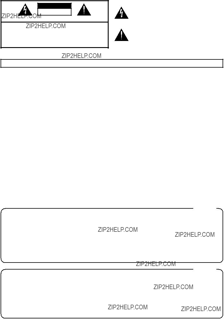
 symbol alerts the user to important instructions or warnings.The specific meaning of the symbol is determined by the design contained within the triangle. In the case of the symbol at left, it is used for general cautions, warnings, or alerts to danger.
 symbol alerts the user to items that must never be carried out (are forbidden). The specific thing that must not be done is indicated by the design contained within the circle. In the case of the symbol at left, it means that the unit must never be disassembled.
 before attempting installation of the circuit board


 Wide
Wide
 - (Roland)


 SAV de votre revendeur ou un service de mainte-


 Use Advanced

 2
2


 (8th note),
  (8th note triplets),
  (16th note),
  (16th note triplets),
  (32nd note),
  (32nd note triplets),
  (64th note), OFF

 A
A B
B


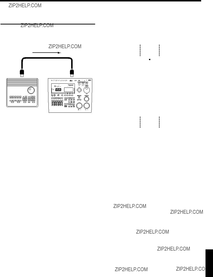
 sound module or sampler
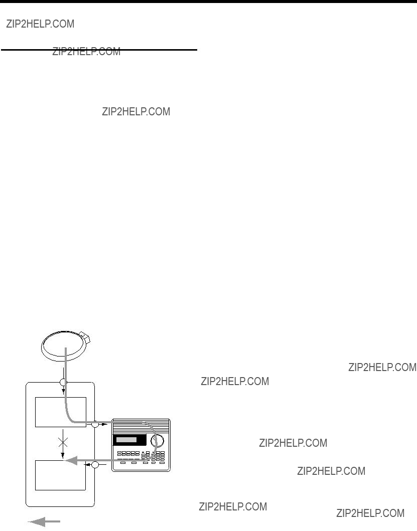


 : An instrument of the percussion group will sound.


 source
  destination