???The flexibility of 40-channel mixing with easy operation enabled by grouping
The M-48 allows you to mix up to 40 channels of digital audio sent via REAC.
You can individually adjust the level and pan of 40 source channels and then assign the 40 sources to 16 stereo groups for convenience.
Volume adjustments on the M-48 are performed on group mixes assigned to each knob, making adjustments extremely quick and easy.
*Settings by the mixing engineer are done from the screen of the M-400 V-Mixer when the M-48 is part of a V-Mixing System. If the
M-48 is connected an alternative mixing console, its settings can be edited from a computer connected to the S-4000 or S-1608 systems.
*In order to edit the M-48???s settings from the M-400, version 2.0 or later system software is required.
*In order to edit from a computer connected to the S-4000 or S-1608 systems, the S-4000 system must have system software version 2.1 or later, and the S-1608 system must have system software 2.0 or later. Version 2.0 or later of the S-4000 RCS application software (Windows XP/ Vista supported) is also required.
System software for each unit and the S-4000 RCS application software can be downloaded at no cost from the Roland Systems Group website (http://www.rolandsystemsgroup.net).
???Unique setups for each musician
Each M-48 on the stage or in the studio can have their own setup.
For example, the drummer???s setup can have each drum mic assigned to its own group (knob), while the keyboard and vocalist audio is combined into a single group. Meanwhile, the vocalist???s setup can combine the drum mics into a single group, while the keyboard and vocal mics each have their own groups.
Musicians do not need to make any compromise in their own monitor setup. Since grouping assignments are per M-48, there???s also no need to use up multiple buses in the mixing console for stage sends, allowing the mixing console to now be used more flexibly.
???Superior sound to support the musician
In order to deliver natural-sounding and comfortable monitor sound, the M-48 provides reverb and 3-band EQ. Since these can be set individually for each group, the musician can obtain their own ideal personal mix.
A limiter is provided to address the problem of excessive volume that can cause discomfort particularly when using headphones. This could mitigate hearing damage that can be caused by sudden high volumes.
An ambient mic with volume control is also provided. This allows the audience???s response to be audible even when wearing headphones. It also allows convenient communication between the musicians on stage or in the studio.
???Connections with external devices
The M-48 can be simultaneously connected to headphones and speakers. You can listen to the monitor sound through headphones while outputting just the low frequencies from a floor monitor so that they can be felt by the entire body.
The rear panel provides an AUX input jack and output jacks for recording. A rhythm machine or metronome can be connected to the AUX input jack so that the musician can conveniently perform start/stop operations or control the tempo. Additionally, by connecting a portable audio recorder (such as one from the EDIROL R-09 series) to the recording output jack, you can record the monitor sound you???re hearing on stage. This lets you take home the recorded monitor sound and use it for practice.
*After the power is turned on (p. 20), audio will not be output until the REAC connection is established.
???No need for AC power cord or AC adaptor
REAC EMBEDDED POWER means that power is supplied from the S-4000D via the REAC cable. No need for an AC power cord or AC adaptor means a less cluttered setup.
*REAC EMBEDDED POWER is technology that uses a Cat5e cable to supply power as well as the REAC audio signals to a REAC device. REAC devices that support REAC EMBEDDED POWER do not require an AC adaptor or AC power cord for their power supply; simply connecting the REAC cable will allow REAC communication as well as supply the power.
???Connect with many types of systems for a variety of uses
In addition to using the M-48 with full-digital connections as part of the RSS V-Mixing System, you can also connect it to a conventional mixing console via the stage unit of a digital snake. From small-scale to large-scale, analog or digital, you can connect and use the M-48 with a wide range of sound mixing systems.
Using the M-48 as part of the V-Mixing System allows full-digital transmission via REAC (Roland Ethernet Audio Communication), delivering high-quality monitor sound to the musicians on stage or in the studio.
*Connections with an alternate mixer require the S-4000 system or S-1608 system.

 Rubber washer (1)
 Wing nut: for 3/8 inch screw (1)
 Washers: for 3/8 inch screw (2)
 Nut: for 5/8 inch screw (1)
 Screws for fastening the

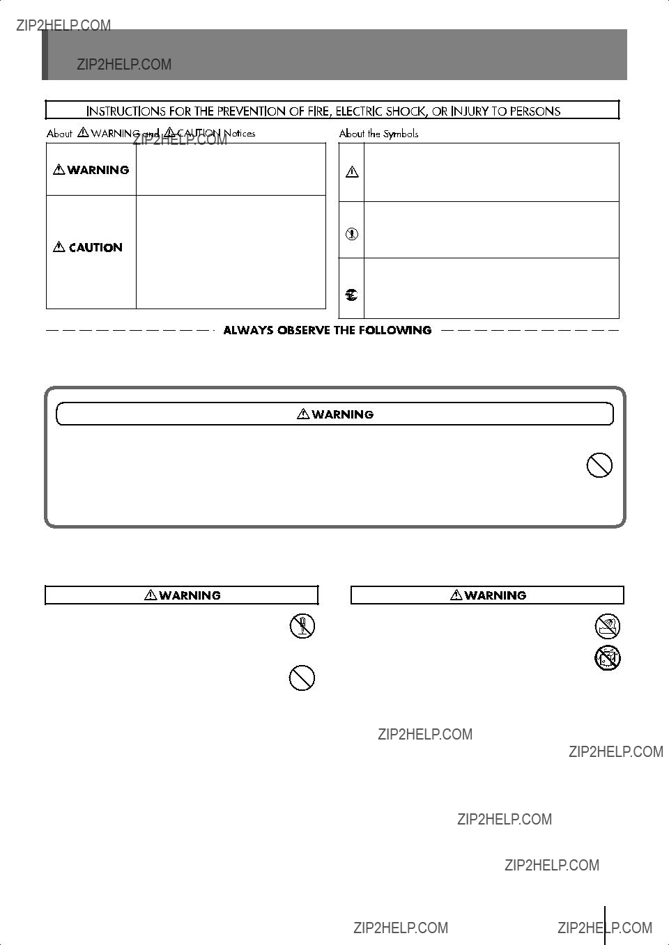
 symbol alerts the user to important instructions or warnings.The specific meaning of the symbol is determined by the design contained within the triangle. In the case of the symbol at left, it is used for general cautions, warnings, or alerts to danger.
 symbol alerts the user to items that must never be carried out (are forbidden). The specific thing that must not be done is indicated by the design contained within the circle. In the case of the symbol at left, it means that the unit must never be disassembled.

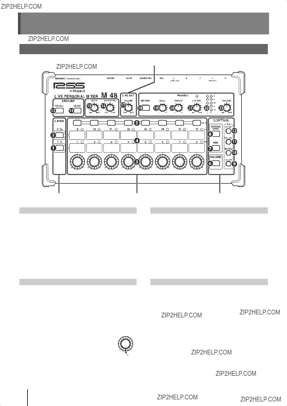

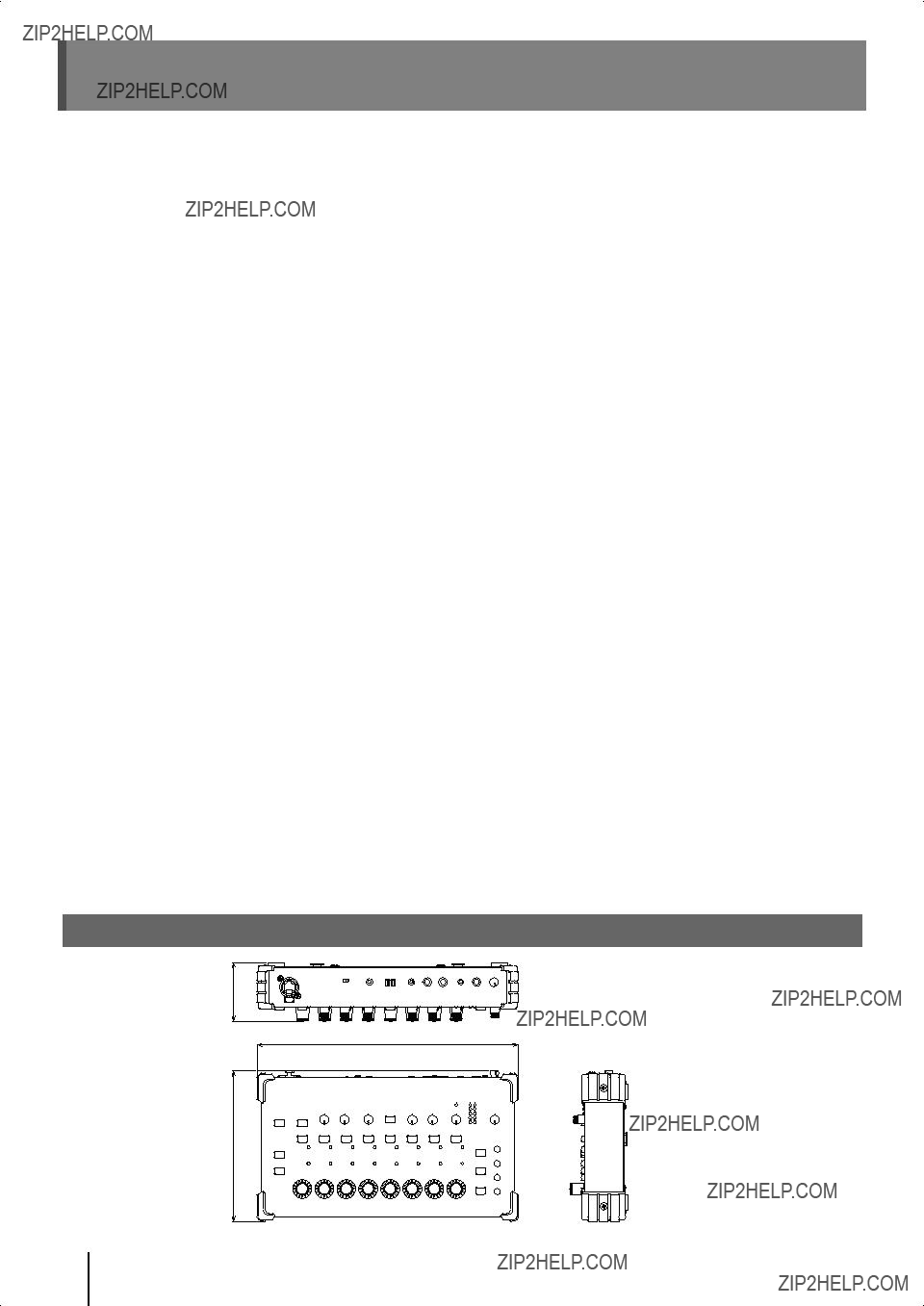
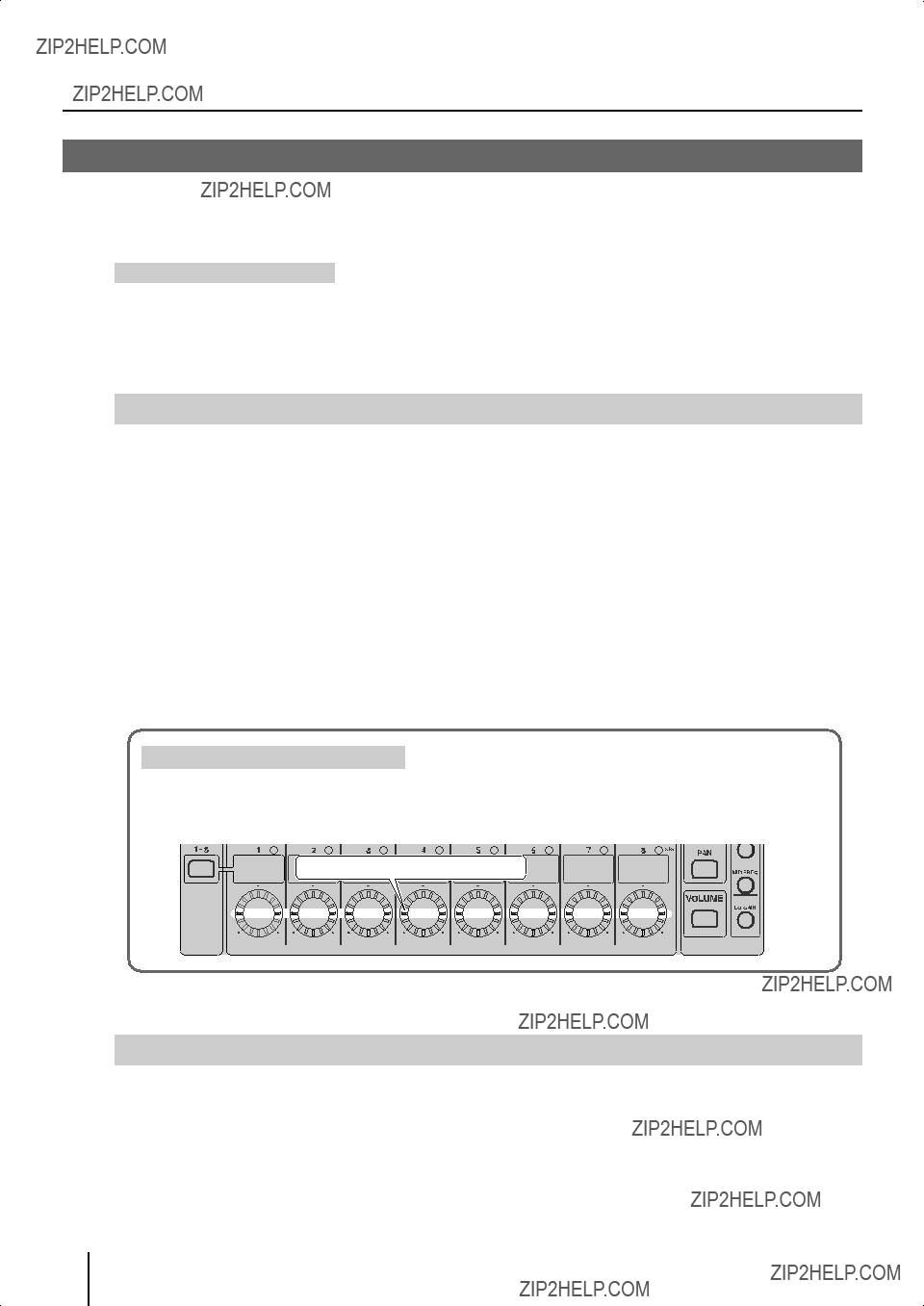
 SIG (signal) indicators
 [SOLO] buttons
 [Control] knobs
 [VOLUME] button
 [PAN] button
 [REVERB SEND] button
 [LO GAIN] button
 [MID FREQ] button
 [MID GAIN] button
 [HI GAIN] button
 [RECALL] button
 [STORE] button
 [AUX IN] knob
 [AMBIENT MIC] mic
 LINE OUT [VOLUME] knob
 [REVERB] button
 [BASS] knob
 [TREBLE] knob
 [LIMITER] knob
 Level meter
 PHONES [VOLUME] knob
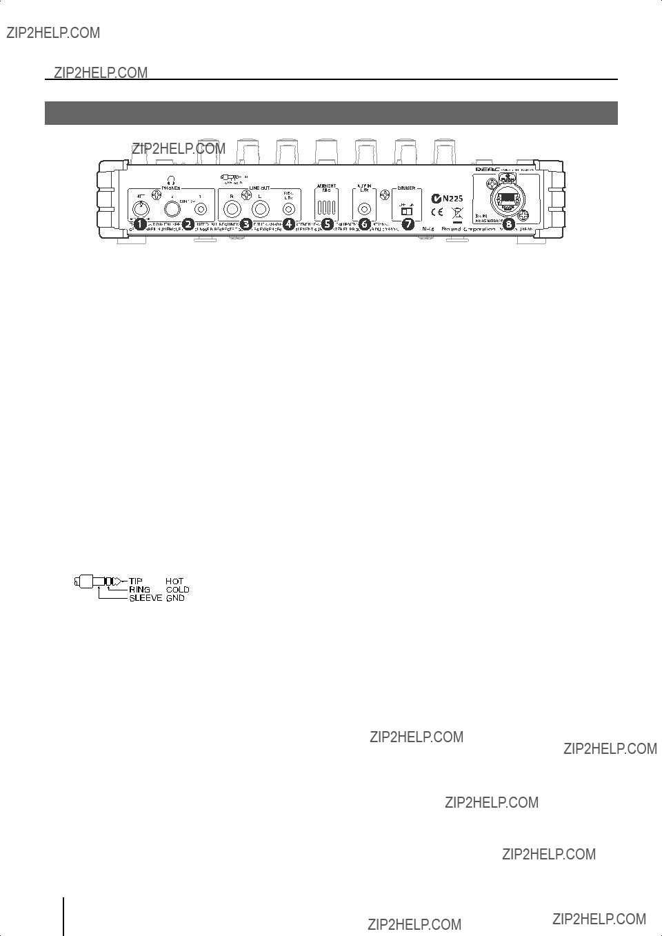
 [ATT] knob
 PHONES jacks 1, 2
 LINE OUT L/R jacks
 LINE OUT REC L/R jack
 AMBIENT MIC
 AUX IN L/R jack
 [DIMMER] switch
 REAC port (supports REAC EMBEDDED POWER)


 ???
???  shown in the illustration.
 ???
???  shown in the illustration.
 Stand holder
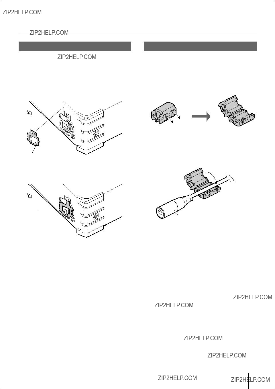
 Connector on the


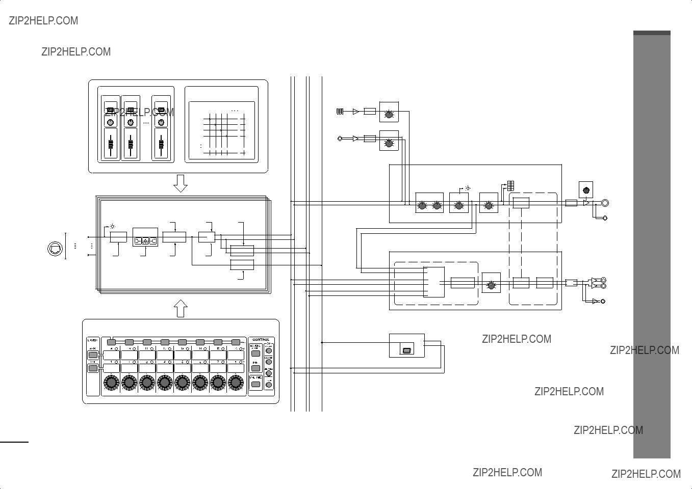
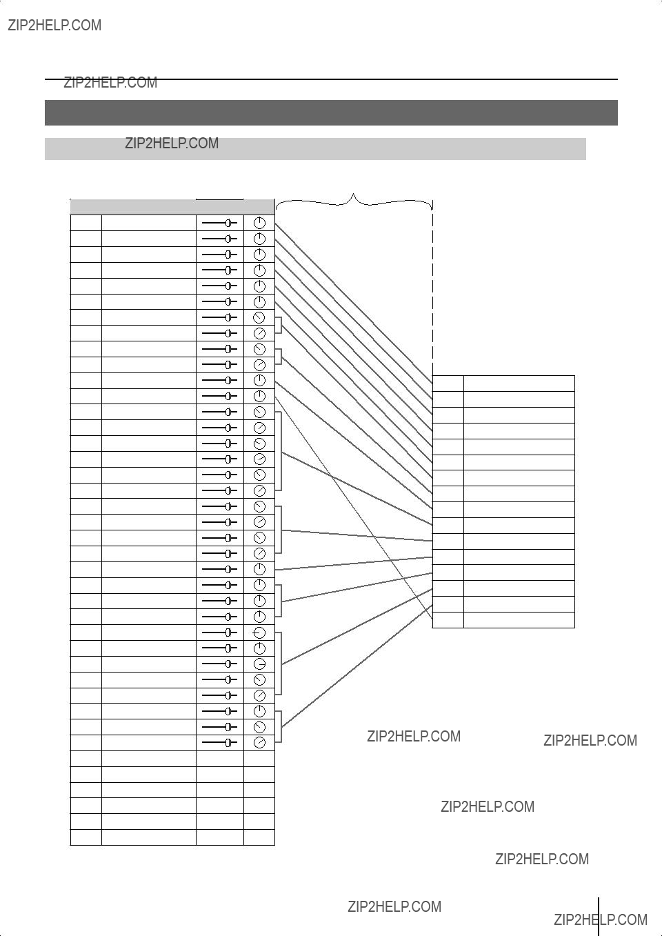
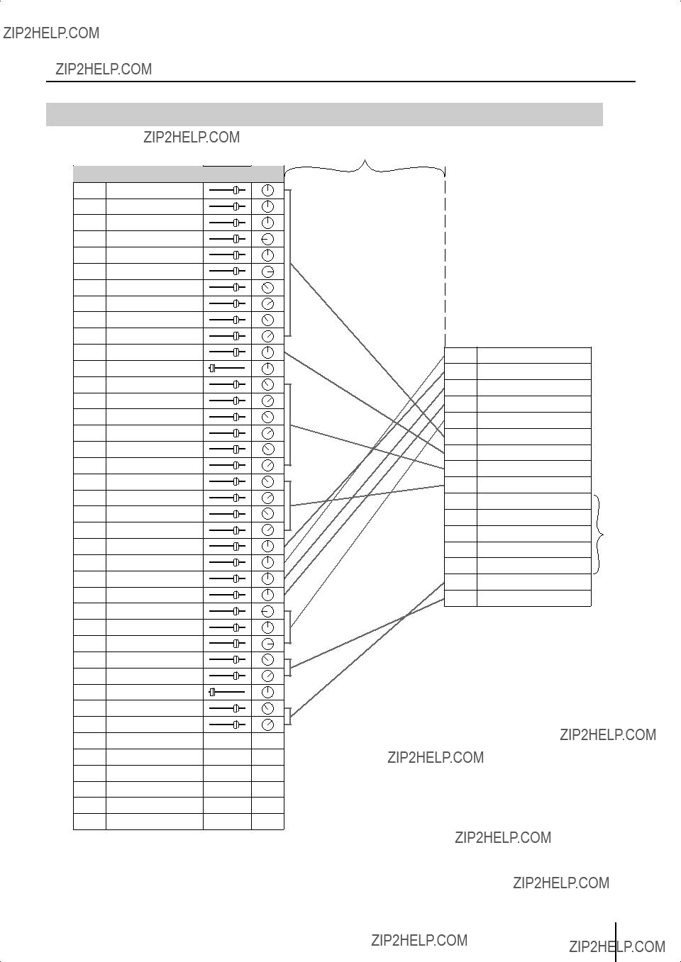
 Source assign settings

 16
16 Group mix
 Group mix
 Source level/pan settings
 Source assign settings


 Lit
Lit
 Lit
Lit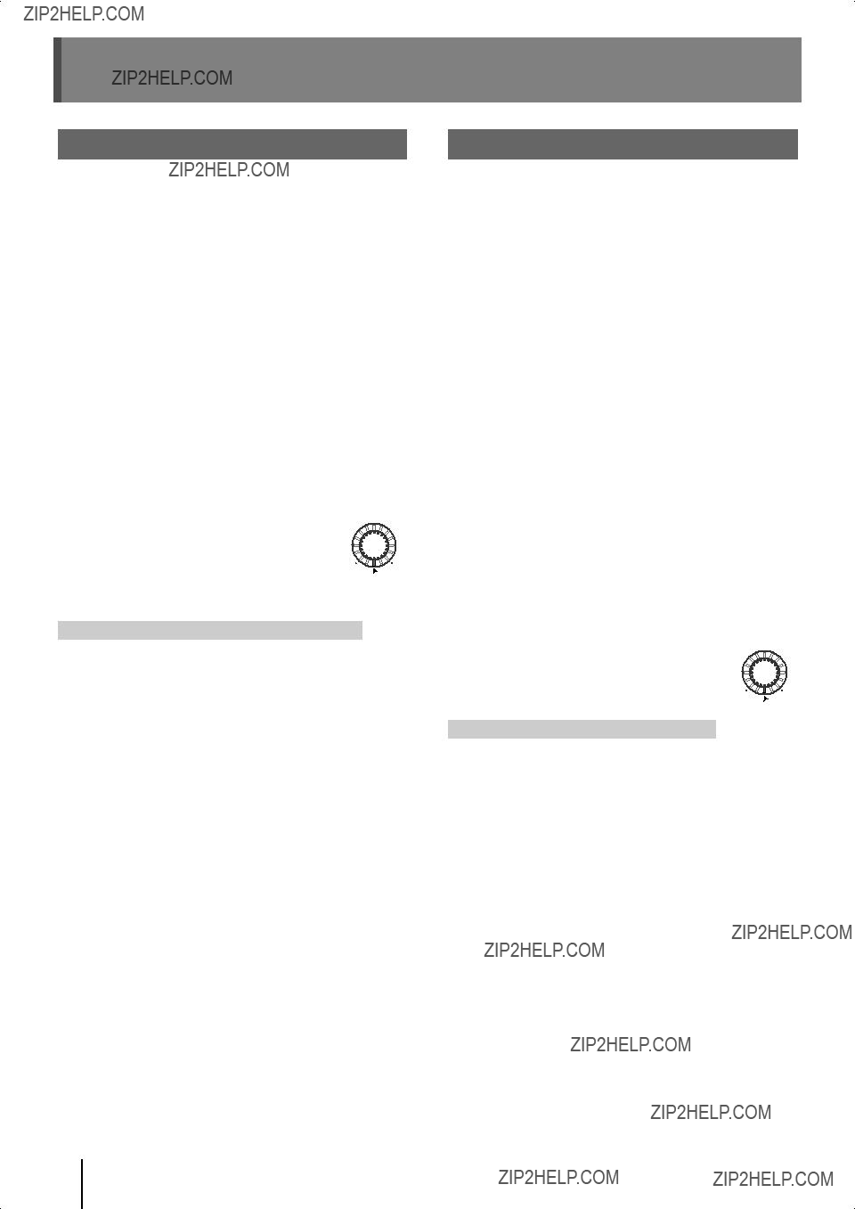
 Lit
Lit Lit
Lit