001
???Before using this unit, make sure to read the instructions below, and the
Owner???s Manual.
............................................................................................
002c
???Do not open (or modify in any way) the unit or its AC adaptor.
............................................................................................
003
???Do not attempt to repair the unit, or replace parts within it (except when this manual provides specific instructions directing you to do so). Refer all
servicing to your retailer, the nearest Roland Service Center, or an authorized Roland
distributor, as listed on the ???Information??? page.
............................................................................................
004
??? Never use or store the unit in places that are:
???Subject to temperature extremes (e.g., direct sunlight in an enclosed vehicle,
near a heating duct, on top of heat- generating equipment); or are
???Damp (e.g., baths, washrooms, on wet floors); or are
???Humid; or are
???Exposed to rain; or are
???Dusty; or are
???Subject to high levels of vibration.
............................................................................................
005
???This unit should be used only with a rack mount adaptor (RAD-50) that is
recommended by Roland.
............................................................................................
006
???When using the unit with a rack mount adaptor recommended by Roland, the
rack must be carefully placed so it is level and sure to remain stable. If not
using a rack or stand, you still need to make sure that any location you choose for placing the unit provides a level surface that will properly support the unit, and keep it from wobbling.
............................................................................................
008c
???Be sure to use only the AC adaptor supplied with the unit. Also, make sure
the line voltage at the installation matches the input voltage specified on
the AC adaptor???s body. Other AC adaptors may use a different polarity, or be designed for a different voltage, so their use could result in damage, malfunction, or electric shock.
............................................................................................
008d
???Take care not to exceed the maximum rated specifications (100 mA) when
using the DC OUT terminal for the power supply.
............................................................................................
009
???Do not excessively twist or bend the power cord, nor place heavy objects on it. Doing so can damage the cord, producing severed elements and short circuits. Damaged cords are fire and shock hazards!
...........................................................................................
010
???This unit, either alone or in combination with an amplifier and headphones or speakers, may be capable of producing sound levels that could cause
permanent hearing loss. Do not operate for a long period of time at a high volume level, or at a level that is uncomfortable. If you experience any hearing loss or ringing in the ears, you should immediately stop using the unit, and consult an
audiologist.
...........................................................................................
011
???Do not allow any objects (e.g., flammable material, coins, pins); or liquids of any kind (water, soft drinks, etc.) to penetrate the unit.
...........................................................................................
012c
??? Immediately turn the power off, remove the AC adaptor from the outlet, and request servicing by your retailer,
the nearest Roland Service Center, or an autho- rized Roland distributor, as listed on the ???Infor- mation??? page when:
???The AC adaptor or the power-supply cord has been damaged; or
???If smoke or unusual odor occurs
???Objects have fallen into, or liquid has been spilled onto the unit; or
???The unit has been exposed to rain (or otherwise has become wet); or
???The unit does not appear to operate normally or exhibits a marked change in performance.
...........................................................................................
013
???In households with small children, an adult should provide supervision until
the child is capable of following all the  rules essential for the safe operation of the unit.
...........................................................................................
014
???Protect the unit from strong impact. (Do not drop it!)
...........................................................................................
015
???Do not force the unit???s power-supply cord to share an outlet with an unrea- sonable number of other devices. Be especially careful when using extension
cords???the total power used by all devices you have connected to the extension cord???s outlet must never exceed the power rating (watts/ amperes) for the extension cord. Excessive loads can cause the insulation on the cord to heat up
and eventually melt through.
...........................................................................................
016
???Before using the unit in a foreign country, consult with your retailer, the
nearest Roland Service Center, or an  authorized Roland distributor, as listed on the ???Information??? page.
101b
???The unit and the AC adaptor should be located so their location or position
does not interfere with their proper ventilation.
...........................................................................................
102d
???Always grasp only the output plug or the body of the AC adaptor when
plugging into, or unplugging from, this unit or an outlet.
...........................................................................................
103b
???At regular intervals, you should unplug the AC adaptor and clean it by using a
dry cloth to wipe all dust and other  accumulations away from its prongs. Also, disconnect the power plug from the power outlet whenever the unit is to remain unused for an extended period of time. Any accumulation of dust between the power plug and the power outlet can result in poor insulation and lead to fire.
...........................................................................................
104
???Try to prevent cords and cables from becoming entangled. Also, all cords and
cables should be placed so they are out of the reach of children.
...........................................................................................
106
???Never climb on top of, nor place heavy objects on the unit.
...........................................................................................
107d
??? Never handle the AC adaptor body, or
its output plugs, with wet hands when plugging into, or unplugging from, an outlet or this unit.
...........................................................................................
108b
???Before moving the unit, disconnect the AC adaptor and all cords coming from
external devices.
...........................................................................................
109b
???Before cleaning the unit, turn off the power and unplug the AC adaptor from
the outlet.
...........................................................................................
110b
???Whenever you suspect the possibility of lightning in your area, disconnect the
AC adaptor from the outlet.
...........................................................................................
118c
???Keep any removed screw terminals, the ground terminal screw, screw terminal
cover, included Euroblock connector,  rubber feet, and card protector attachment screws safely out of children???s reach so as to prevent these pieces from being swallowed accidentally by young children.
...........................................................................................
 are trademarks of SanDisk Corporation and licensed by CompactFlash association.
 ) trademarks.
 symbol alerts the user to important instructions or warnings.The specific meaning of the symbol is determined by the design contained within the triangle. In the case of the symbol at left, it is used for general cautions, warnings, or alerts to danger.
 symbol alerts the user to items that must never be carried out (are forbidden). The specific thing that must not be done is indicated by the design contained within the circle. In the case of the symbol at left, it means that the unit must never be disassembled.
 IMPORTANT NOTES
 Contents
 Panel Descriptions
 Installation

 Cards Handled by the
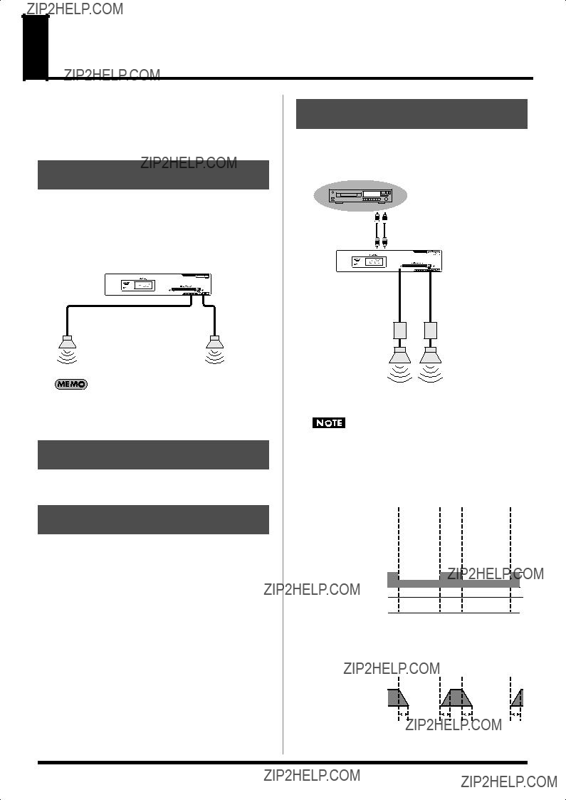
 Audio Signal
 Control Signal
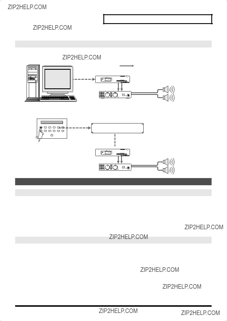
 AR Control with a computer
 Control signal Audio signal
 Explanatory messages and guidance for public facilities and museum exhibits


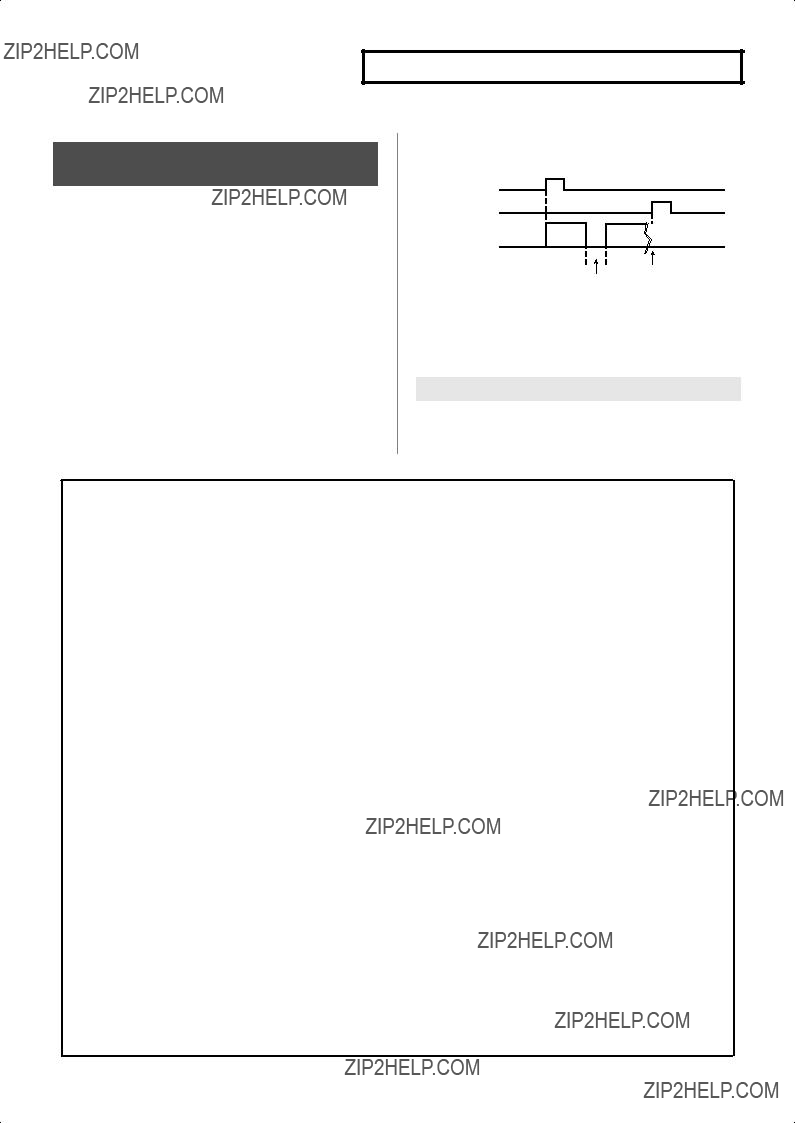

 Recording Instructions (Terminal Rec)
 11111000
 11111001
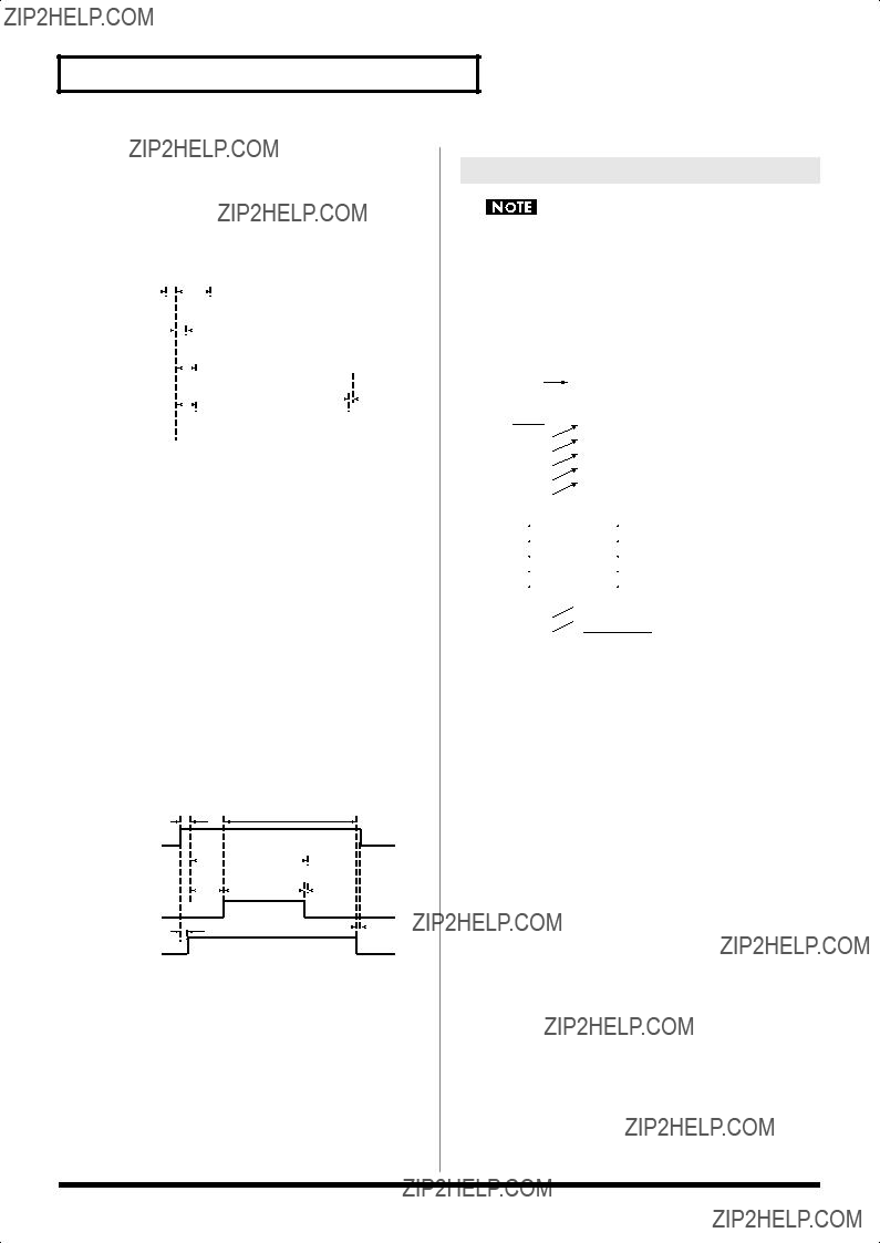
 About Control Using
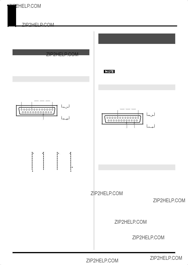

 Troubleshooting
 Error Messages
 Regarding Cards
 MODE SW Settings
 Control I/O Connector Specifications
 Specifications
 Index
Index
